


GrowSpan™ 42' Wide Series 500
Tall High Tunnels with Roll-Up Sides
Photo may show a building of a different length and style. Frame shown includes drop-down sides and customersupplied baseboards. Actual cover material may differ. Building shown is equipped with an optional roll-up end.
©2019 All Rights Reserved. Reproduction
prohibited without permission.
Revision date: 03.06.19
42' Wide Series 500 Tall High Tunnels:
All Standard Lengths.
1
Important Information
LOCATION
Choosing the proper location is an important step before
you begin.
The following suggestions and precautions will help
determine whether your selected location is the best
location.
READ THIS DOCUMENT BEFORE YOU
BEGIN TO ASSEMBLY
Thank you for purchasing a Series 500 high tunnel.
When properly assembled and maintained, this product
will provide years of reliable service. These instructions
include helpful hints and important information needed
to safely assemble and properly maintain the structure.
Please read these instructions before you begin.
If you have any questions during the assembly, please
contact customer service for assistance.
SAFETY PRECAUTIONS
• Wear eye protection.
• Wear head protection.
• Wear gloves when handling metal parts.
• Use a portable GFCI (Ground Fault Circuit Interrupter)
when working with power tools and cords.
• Do not climb on the frame during or after construction.
• Do not occupy the structure during high winds,
tornadoes, or hurricanes.
• Never erect the structure under power lines.
• Identify whether underground cables and pipes are
present before preparing the site, setting ground
posts (if equipped), or anchoring the structure.
• Location should be away from structures that could
cause snow to drift on or around the building.
• Do not position the structure where large loads
such as snow and ice, large tree branches, or other
overhead obstacles could fall.
• Always check local building codes before you begin
and follow codes as instructed.
SITE
After choosing a location, proper preparation of the site is
essential. Follow the information below.
• A level site is required. The site must be level to
properly and safely erect and anchor the structure.
• Drainage: Water draining off the structure and from
areas surrounding the site should drain away from
the site to prevent damage to the site, structure, and
contents of the structure.
• Provide adequate ventilation if the structure is
enclosed.
• Do not store hazardous materials in the structure.
• Provide proper ingress and egress to prevent
entrapment.
SETTING THE GROUND POSTS
The frame assembly of this building requires the
setting of all ground post in concrete. Review the
layout diagrams for additional details.
Enlist the services of a professional and competent
contractor to prepare the site and set the ground posts.
Failing to secure ground posts in concrete as required
may result in damage to the building, building contents,
and surrounding property.
2
WARNING: The individuals assembling this structure
are responsible for designing and furnishing all
temporary bracing, shoring and support needed
during assembly. For safety reasons, those who are
not familiar with recognized construction methods
and techniques must seek the help of a qualified
contractor.
S500_42_Wide_HT_Roll_up Revision date: 03.06.19

ASSEMBLY
Important Information
Following the instructions as presented will help ensure
proper assembly. Failing to follow these steps may result
in an improperly assembled and anchored structure.
NOTE: Once the main frame is assembled, many of
the remaining procedures can occur simultaneously,
depending on available assistants and equipment.
Before you begin, review all technical documents to
better understand overall building design.
The steps outlining the basic frame assembly are as
follows:
1. Verify that all parts are included in the shipment.
Notify Customer Service for questions or concerns.
2. Read this guide and all additional documentation
included with the shipment before you begin.
3. Gather the tools, bracing, ladders, lifts, and
assistants needed to assemble the structure.
4. Check the weather before you install the roof cover
and any end panels (if equipped). Do not install
covers or panels on a windy or stormy day.
5. Re-evaluate the location and site based on the
information and precautions presented in the
documentation included with the shipment.
6. Prepare the site (if applicable). Set ground posts in
concrete, or attach base plates to concrete. If building
includes end framing, review those instructions and
drawings for additional end framing requirements.
7. Assemble rafter components and rafter support kit
components (if equipped). Optional support kits
require an additional purchase.
14. Install roll-up (or drop-down) sides and anti-billow
ropes.
15. Complete and return all warranty information as
instructed if present.
REQUIRED TOOLS
The following list identifies the main tools needed to
assemble the shelter. Additional tools and supports may
be needed depending on the structure, location, and
application.
• Tape measure or measuring device and marker to
mark locations on the pipes and rafters.
• Variable speed drills and impact drivers. (Cordless
with extra batteries works best.)
• Metal-cutting saws or tools to cut pipe and
aluminum.
• Drill bit set with 5/16" bit and 1-3/4" hole saw bit (if
polycarbonate end panels are installed)
• Wrenches and impact socket set, hammer, and
gloves.
• Adjustable pliers and self-locking pliers.
• Ladders, work platforms, and other machinery for
lifting designed to work safely at the height of the
building.
• Safety equipment to protect head, eyes, hands and
feet.
UNPACK AND IDENTIFY PARTS
8. Assemble main building frame (rafters, cabling,
purlins, etc).
9. Attach baseboards and ribbon boards (customersupplied).
10. Attach 102197 aluminum u-channel along the sides
for cover installation. Consult these instructions and
all drawings for additional details.
11. Install end wall frame, door frame, and end wall
cladding if equipped.
12. Attach 111613Z144 to the end rafters.
13. Install main cover.
Revision date: 03.06.19 S500_42_Wide_HT_Roll_up
The following steps will ensure that you have all the
necessary parts before you begin to assemble the
shelter frame.
1. Unpack the contents of the shipment and place
where you can easily inventory the parts. Refer to
the Bill of Materials/Spec Sheets.
2. Verify that all parts listed on the Bill of Materials/
Spec Sheets are present. If anything is missing
or you have questions, consult the Pictorial Parts
Guide and all diagrams for clarification, or contact
Customer Service.
NOTE: Do not open plastic bags containing smaller
parts such as fasteners or washers at this time.
Simply verify quantity.
3

Baseboards and Ribbon Boards
A customer-supplied baseboard is recommended for
roll-up sides that include the stabilizer bar. A baseboard
runs the length of the frame and provides a seal between
ground level and the stabilizer bar.
All baseboard and ribbon board material and
fasteners to secure these to frame are supplied by
the customer. See photo below.
Stabilizer Bar
Baseboard
Secure baseboard (and ribbon
board) joints between rafters
as shown for best results.
RIBBON BOARD FOR ROLL-UP SIDES—OPTIONAL
In some instances, a ribbon board is installed along
the side of the frame. This is optional for buildings with
roll-up side panels. Customer supplies the materials and
fasteners for the ribbon board.
End View
FAH005B Bolt
111613Z144
5/16" Carriage
Bolt (minimum)
supplied by
customer
2" x 6"
Ribbon Board if used.
(supplied by customer)
FALB01B Nut
FALF01B Fender
Washer
Rafter Leg
or Ground
Post
Inside of
Shelter
Ground
Level
Outside of
Shelter
Dimensions
Recommended baseboard dimensions are 2" x 8" and
ribbon board dimensions are 2" x 6" (minimum).
Recommendation: Use two (2) 1/2" carriage bolts
(exterior finish) per rafter connection to secure
baseboards and two (2) 5/16" carriage bolts (minimum)
to secure ribbon boards to rafter legs/ground posts.
Actual frame shown in the examples above may differ.
These are presented for illustration purposes only.
1/2" Carriage
Bolt (supplied
by customer)
2" x 8" Baseboard
(customer supplied)
DIAGRAMS ARE NOT TO SCALE.
Ground
Level
4
S500_42_Wide_HT_Roll_up Revision date: 03.06.19
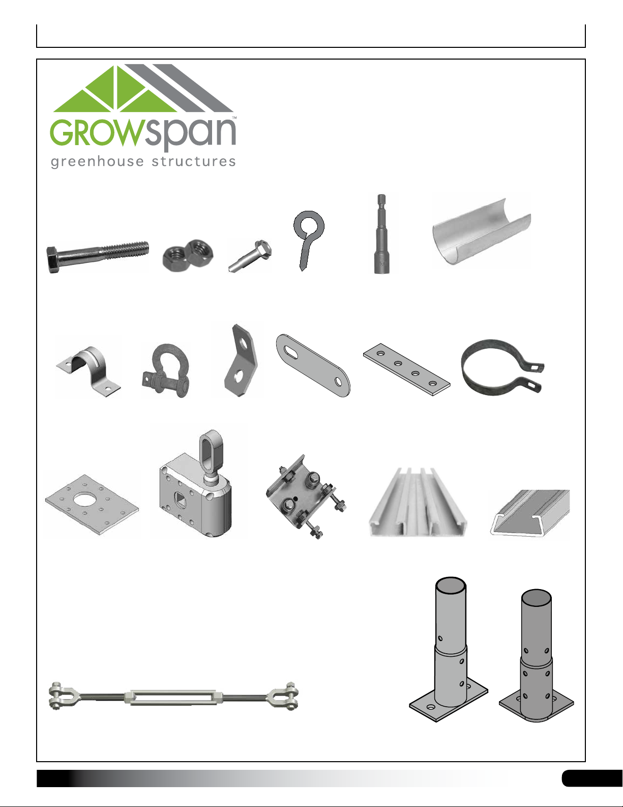
Parts Identication
The following graphics will help identify the basic
parts of the frame. (Some parts are not shown.)
105370B
1/2" x 4-1/2" Hex Bolt
QH1070
Pipe Strap
103544
Mounting Plate
(Roll-Up or Drop-
Down Sides only)
AS2167 Anchor
FALB08B
1/2" Nut
108503 Cable
Shackle
103496
Gear Box
(Roll-Up or Drop-
Down Sides only)
FA4482B
Tek Screw
Bracket
FA2155 Lag
Eye Screw
PGBRKAAS01
Bracket
102569 Roller
Bearing
(Roll-Up Sides only)
100441 Magnetic
Nut Setter
GS0049
Splice Plate
111613Z144
CC6212
Fabric Clip
115480 Band
Clamp
102197 Aluminum
U-Channel
104189 Turnbuckle
Revision date: 03.06.19 S500_42_Wide_HT_Roll_up
115356 115355
5
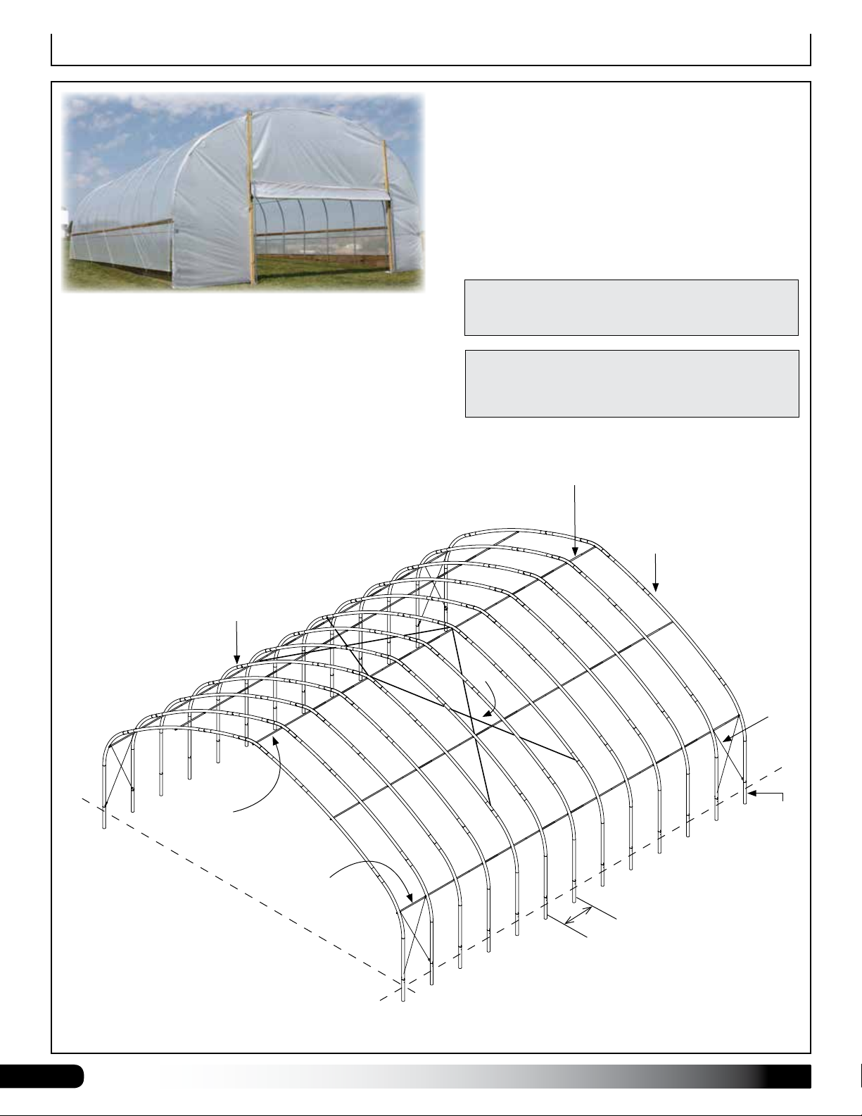
Overview
Sample building shows drop-down sides and optional roll-up
door panel. (Wood for end frame is supplied by the customer.)
GrowSpan™ 42' Wide
Series 500 Tall High Tunnels
Drawing may show a model of a different length. Refer to
Quick Start section located near the back of this guide for
on-center measurements and post layout.
OVERVIEW
This section describes assembling your building frame.
See illustration below to identify main parts.
1. Prepare site and set ground posts in concrete, or
install base plates, depending on option.
2. Locate the required parts for each assembly
procedure.
3. Assemble the rafters and main frame.
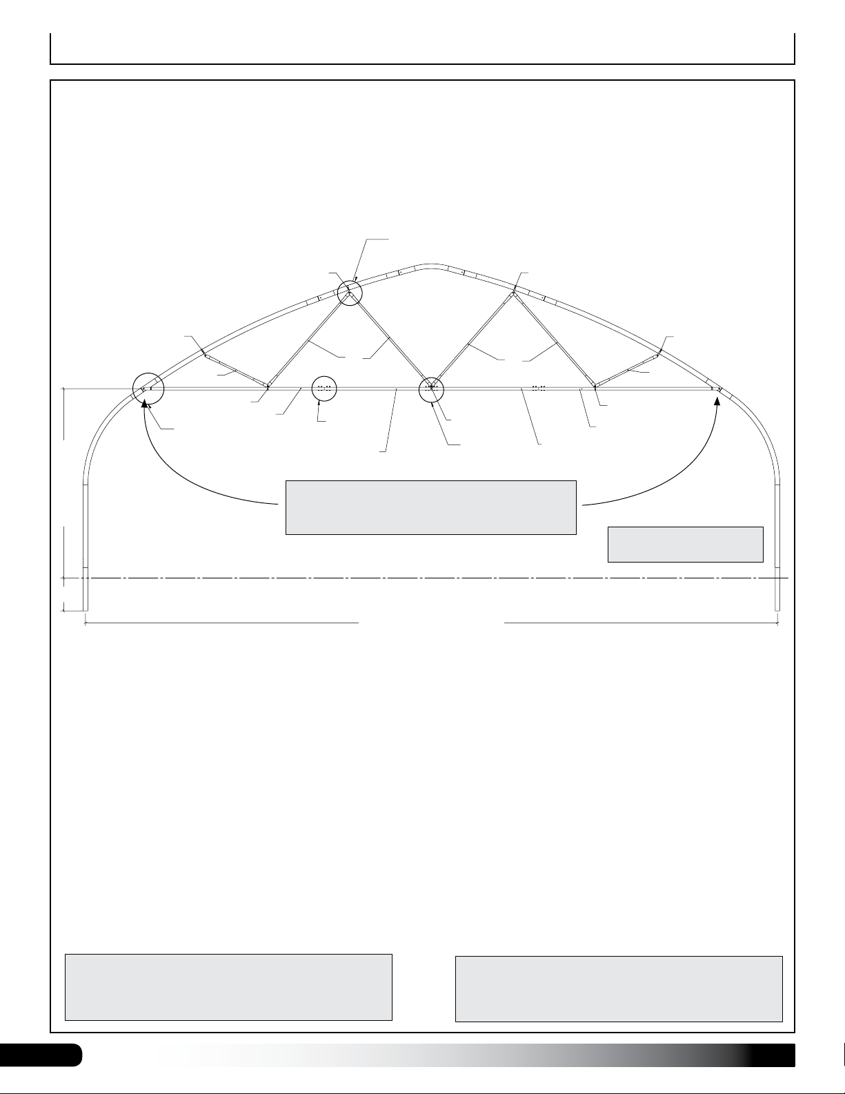
Interior Rafter
GROUND POST OPTION SHOWN BELOW AND IN
MOST DIAGRAMS THROUGHOUT THIS GUIDE. SEE
QUICK START SECTION FOR ADDITIONAL GROUND
POST AND BASE PLATE DETAILS.
Ridge Purlin
End Rafter
Cable
Cable
Ridge
Purlin
Ground Level
6
Side
Purlin
On-Center
Rafter Spacing
S500_42_Wide_HT_Roll_up Revision date: 03.06.19
Ground
Post
Prepare and Square the Building Site
PREPARE THE BUILDING SITE
A level site is required to accurately and safely construct
the building. Consult the services of a qualified contractor
to properly grade and prepare the site.
Site should slope away from the building for proper water
drainage.
After the site is prepared, mark the location of the frame
corners to square the frame position. Taking these steps
before assembling the shelter saves time and ensures
that the structure is square and positioned as desired.
The following procedures are suggested methods.
Their use depends on the size of the shelter, shelter
application, the footings (if applicable), and the method
used to anchor the shelter.
When in doubt, consult the services of a qualified
contractor experienced with the construction of similar
structures.
Base Plates
SQUARE THE SITE: GENERAL STEPS
1. Identify a corner where a building rafter will be
positioned, drive in a stake, and string a line the exact
width of the building and stake in place. (Width of the
rafter is measured from center-to-center of the rafter
pipes/ground posts.)
2. After the first corner stake is in place, string a line the
width of the building (center-to-center) and drive the
second corner stake into the ground.
3. String a line at least as long as the building 90° from
the line between the first and second stakes.
If your frame includes base plates, prepare the site and
anchor the base plates to concrete before assembling
the frame. Layout the site and continue with Base Plates
Option section.
Base plates can be anchored to a concrete slab or
concrete piers. Consult Ground Post section for concrete
pier layout, then continue with Base Plates section.
Ground Posts
If the frame includes ground posts, set all ground posts
as described within this manual. Width of the shelter
is measured from the center of one ground post to the
center of the remaining ground post. Length is also
measured center-to-center. If your building includes
ground posts, continue with the Setting Ground Post
section.
SETTING THE GROUND POSTS
The frame assembly of this building requires the
setting of all ground post in concrete. Review the
layout diagrams for additional details.
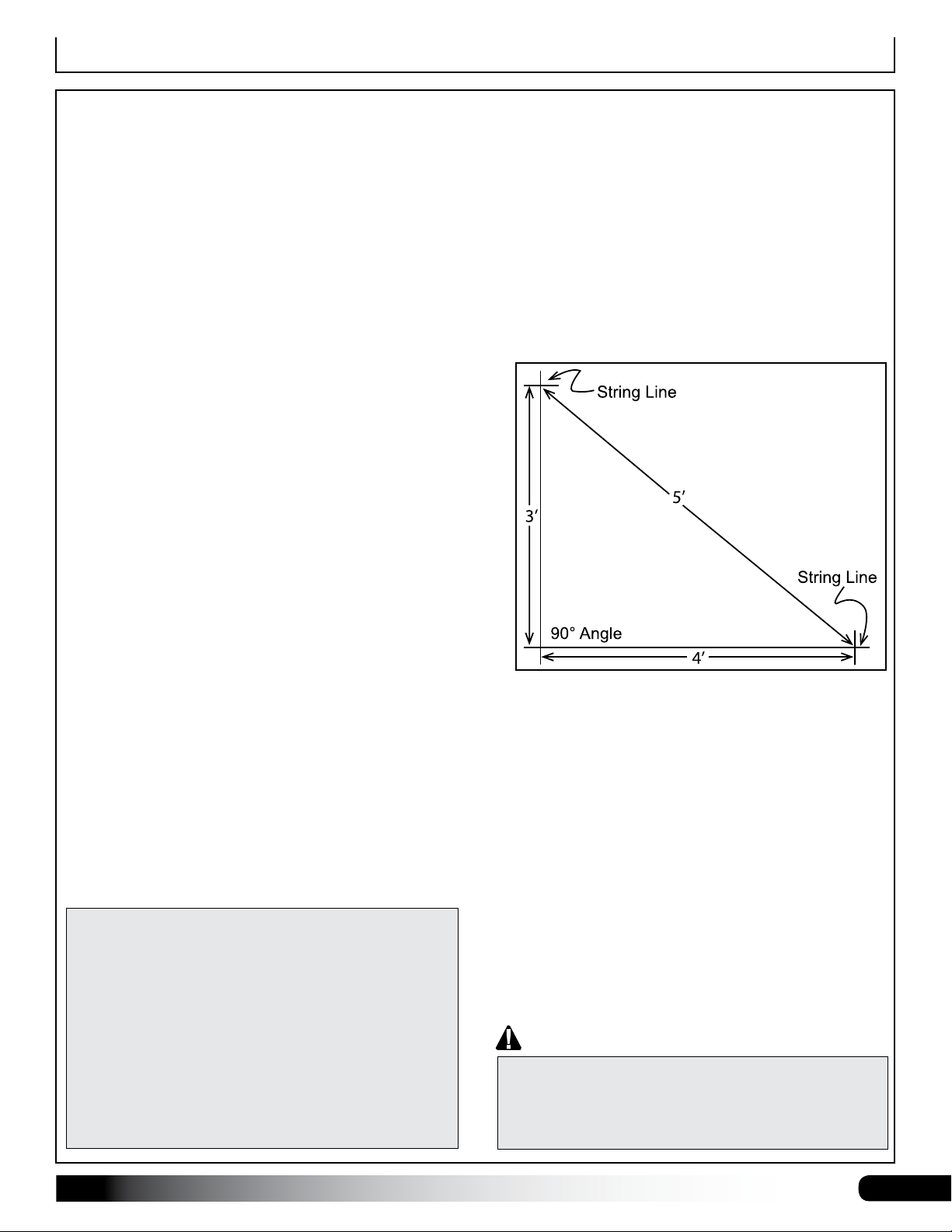
NOTE: A transit can be used to ensure an accurate
90° angle, or the 3-4-5 rule can be used. Refer to
diagram. Using multiples of 3-4-5 such as 6-8-10 or
12-16-20 helps to maintain an accurate 90° angle.
4. After squaring the position of the building, measure
the length and drive the third corner stake.
5. Repeat the same step for the last corner stake.
NOTE: The distance measured diagonally between
corner stakes must be equal for the building to be
square.
Enlist the services of a professional and competent
contractor to prepare the site and set the ground posts.
Failing to secure ground posts in concrete as required
may result in damage to the building, building contents,
and surrounding property.
Revision date: 03.06.19 S500_42_Wide_HT_Roll_up
IMPORTANT: Do not drive ground posts into the
ground! Doing so will damage the swaged end making
it difficult if not impossible to set rafter onto the posts
during frame assembly.
7
Set Ground Posts
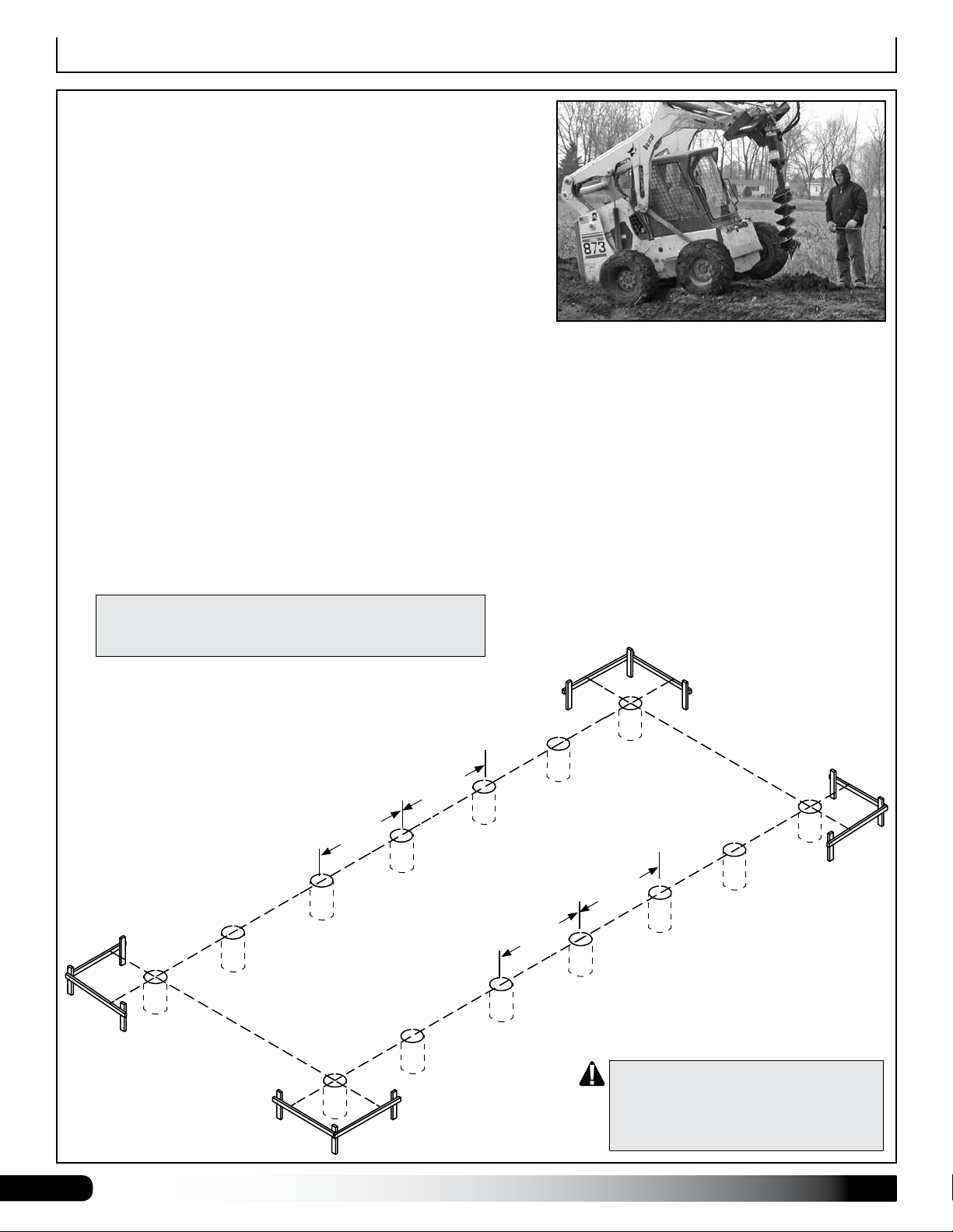
MARK THE SITE AND DIG POST HOLES
These steps describe marking all post hole locations and digging
the holes. For some sites, it may not be possible to complete the
procedure in this manner. An alternative procedure such as working
from one end of the building toward the other may be necessary.
Determine the best procedure based on the site and other factors
and proceed as needed.
NOTE: Refer to the Quick Start Section located near the back
of these instructions for the Side Profile and related diagrams.
Complete these steps:
1. Stake the outline of the building using string line and batter boards. Set batter boards 3' back from the building
corners. Check to ensure that the building layout is square. Cover or panels (if equipped) will not install properly if
the building frame is not square once assembled.
2. Consult the diagrams in the Quick Start section to verify the frame length and width dimensions and to accurately
position the ground posts.
3. Guided by the string line, use a flag or stake to mark each ground post hole location.
4. Move the string line and dig a post hole a minimum of two feet (2') deep or to a depth that is below the geographic
frost line. Consult local building codes. A power auger works best. Minimum hole diameter is 12".
5. After digging all holes, reattach the string line to the batter boards and use it as a guide to set and align the
ground posts.
Drawing may show layout of a different length. Refer to
Quick Start section located in the back of these instructions
for on-center measurements and post layout for your frame.
on-center
on-center
on-center
on-center
ATTENTION: Do not drive ground posts
into the ground! Doing so will damage
the swaged end making it difficult if not
impossible to set rafter onto the posts
during frame assembly.
8
S500_42_Wide_HT_Roll_up Revision date: 03.06.19
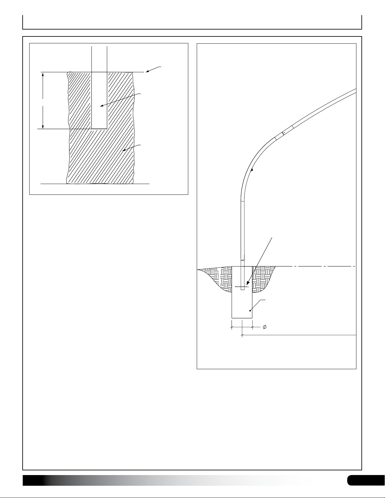
Set the Ground Posts — Diagrams
GROUND LEVEL
42'-0" CENTER TO CENTER OF GROUND POSTS
Ground Level
Ground Post
2’ Deep
Concrete
In areas where frost is common, dig each post hole so
it falls below the frost line. Minimum hole depth for all
areas regardless of frost is 24". Minimum hole diameter
is 12". Set all ground posts 24" in concrete.
Consult local building codes and qualified contractors for
additional details when digging the post holes and setting
the ground posts.
Optional: Before setting the
posts, drill a hole through the
bottom of each ground post
2"-3" from the end and insert
a 6"-8" length of rebar through
it. This will help stabilize and
anchor the ground posts once
the concrete sets.
Follow established codes and construction practices.
CONCRETE PIER
12"
Revision date: 03.06.19 S500_42_Wide_HT_Roll_up
9
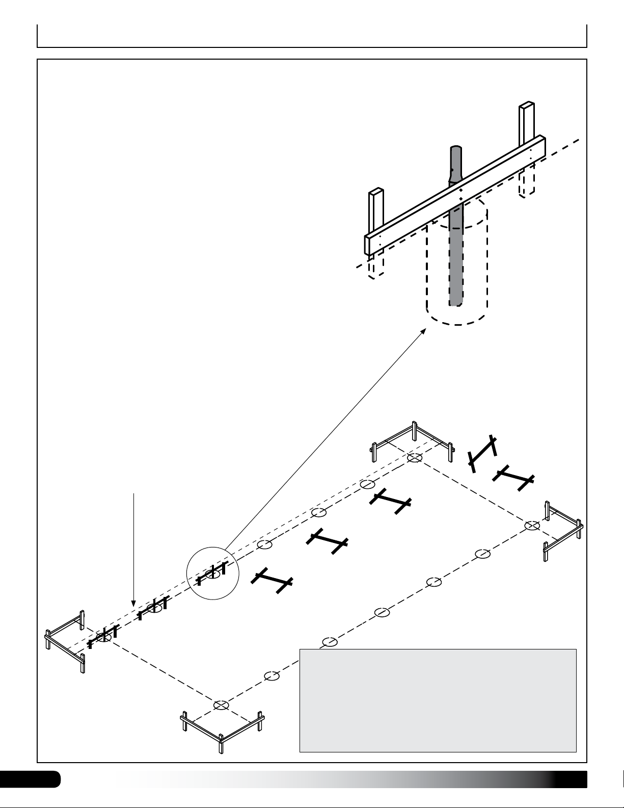
Set Ground Posts
SET GROUND POSTS
Required parts and equipment:
• Ground Posts (113102)
• Equipment and materials to level and brace posts
NOTE: Concrete (customer-supplied) is required to secure all
ground post in the holes. Set all posts at the same height for
proper assembly. Position all rafter mounting holes to point toward
the outside/inside.
Consult the services of a qualified contractor to properly set posts.
Here are the basic steps:
1. Take one ground post, measure 24" from the end opposite the
bolt holes, and mark the location on the ground post. Repeat
to mark all ground posts.
NOTE: The rafter mounting bolt hole is near the top of the
ground post and is drilled through the swaged section.
Baseboard holes are below the rafter mounting hole.
2. With assistance, set and brace all posts in place. See diagram
below. All posts are to be plumb before adding concrete.
Use the baseboard mounting holes and customer-supplied
fasteners and stakes to hold posts in place.
Stake Ground Posts for Concrete
Set all posts at the
same height. Additional
bracing may be needed
to keep the post plumb
while concrete sets.
Customer-supplied braces
and fasteners.
Ground
Level
3. Add concrete to anchor posts in holes. Fill hole so concrete
remains below ground level.
Set top of posts at the same
height. Set lower 24" of post
in concrete.
SETTING THE GROUND POSTS
The ground posts include pre-drilled rafter mounting bolt
holes and holes to attach baseboards. Position rafter
mounting holes so they point to the ends of the frame.
10
Baseboard attachment holes will then be positioned to
point to the outside/inside of the frame.
S500_42_Wide_HT_Roll_up Revision date: 03.06.19
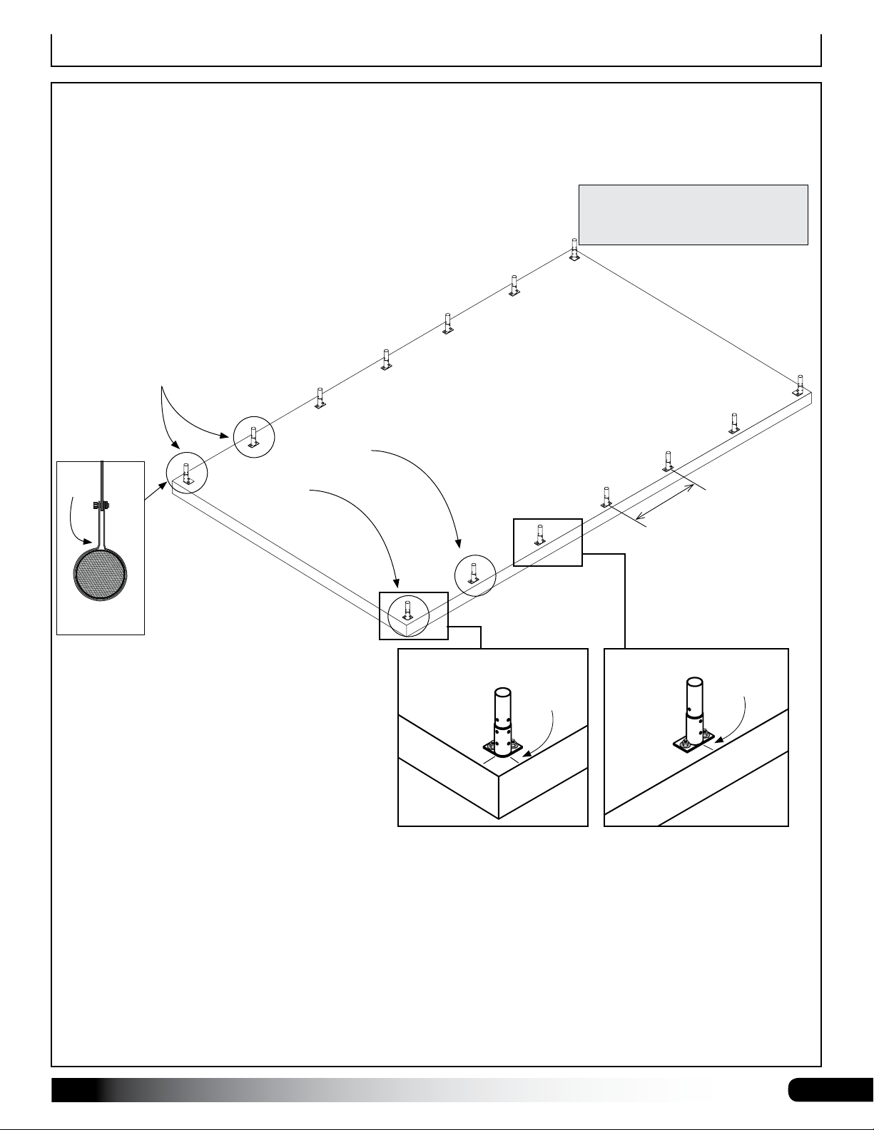
Base Plates (Option)
SETTING THE BASE PLATES
For those buildings equipped with base plates, secure the plates to either a concrete foundation or concrete piers
prior to attaching the rafter legs and assembling the frame. Customer is responsible for construction of the necessary
concrete foundation or concrete piers. Consult and follow local and regional building codes for slab requirements.
Once concrete has cured, attach base plates. Ensure base plates are
aligned and spaced according to layout diagram in Quick Start section
located near the back of this guide. Attach using the appropriate
mounting hardware (purchased separately).
Plates must be aligned, plumb, and set at
correct, uniform height for proper assembly.
ATTENTION: Slide two (2) 115480 band
clamps over each base plate of first two
rafters at each end for side cable attachment.
See circles below.
Two (2)
TOP VIEW
Band
Clamp
End
Rafter
Two (2)
clamps here.
See page 15 for
additional details.
clamps here.
ATTENTION: Enlist the services
of a qualified contractor to properly
layout and set base plates.
Frame length may differ
from diagram shown.
4' On-Center
Diagrams not to scale.
General Anchor Bolt and Epoxy (recommended)
Installation Steps:
115355
Corner
Base Plate
Align Marks
115356
Mid
Base Plate
Align Marks
1. Using the Rafter Layout – Base Plates
diagram in Quick Start section, determine
on-center positions of base plates. Use a
string line to maintain alignment.
2. Square plate on foundation and mark bolt
Concrete
Concrete
hole and base plate locations using base
plate as a template.
3. Remove base plate and drill mounting holes according to requirements of customer-supplied anchor bolts.
4. Clean bolt holes according to anchor bolt specifications and directions on epoxy container.
5. Once holes are clean, set plate back in place and apply recommended epoxy into each hole as described by
epoxy manufacturer.
6. Take anchor bolts (with nuts and washers installed) and carefully insert one into each bolt hole. Adjust nut and
washer on anchor bolt to gauge how far bolt will drop into hole.
7. Allow epoxy to set according to manufacturer's instructions before tightening.
8. Repeat procedure to install remaining base plates.
9. After epoxy has set, return to all anchor bolts and tighten according to manufacturer's instructions.
Revision date: 03.06.19 S500_42_Wide_HT_Roll_up
11
Rafter Assembly
RAFTER ASSEMBLY
After setting the ground posts, continue with the rafter assembly. Do not set assembled rafters into position on the
ground posts until concrete has set. Check with contractor for set times.
NOTE: All rafter assemblies consist of seven (7) main rafter sections. Consult the rafter diagrams in the Quick Start
section of these instructions before and during the rafter assembly for details. Assistance is required to assemble the
rafters and frame. If space allows, assemble all main sections of rafters as described below and set aside.
PG500TC3514S423 PG500TC3514S423
PG500TC3514S424
PG500TC3514S422 PG500TC3514S422
PG500TC3514S425 PG500TC3514S425
42' Wide Rafter
(no ground posts shown)
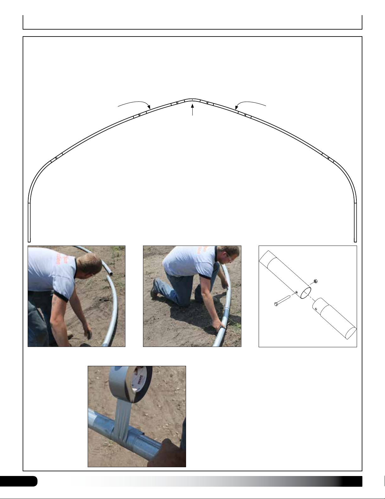
1. Select the seven (7) rafter pipes
to assemble one rafter
2. Slide the separate pipe sections
together to assemble rafter.
3. Secure each rafter joint using a
1/2" x 4-1/2" bolt (105370B) and
1/2" nut (FALB08B).
12
4. Verify that each bolt is tight and wrap each
splice and bolt with duct tape to protect the
cover during installation.
S500_42_Wide_HT_Roll_up Revision date: 03.06.19
Rafter Assembly
RAFTER ASSEMBLY (continued)
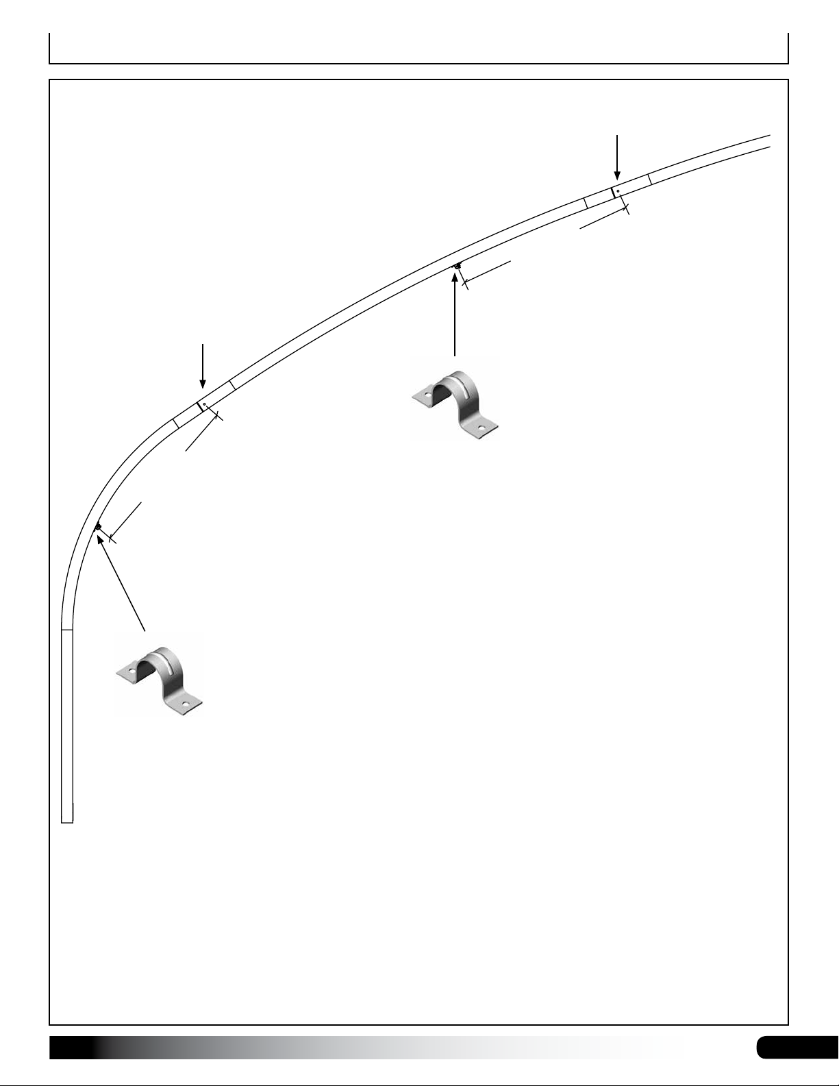
ATTENTION: Measure from the mounting
bolt to the rafter and mark the location.
1/2" Mounting Bolt
at Rafter Splice
"
8
/
5
2
-
'
4
QH1070
Pipe Strap
4'
1/2" Mounting Bolt
at Rafter Splice
6
1
3/
-7
QH1070
Pipe Strap
5. Use the diagram above and in the Quick Start section to mark the purlin clamp (QH1070) locations on the
underside of the assembled rafter.
ATTENTION: Measure from the mounting bolt to the rafter and mark the location.
6. Loosely install QH1070 clamps. Tighten clamps after purlins are installed. See connection details in the Quick
Start section at the back of this manual.
Revision date: 03.06.19 S500_42_Wide_HT_Roll_up
See full Rafter Profile in Quick Start
section for all QH1070 bracket locations.
13
Rafter Assembly–Optional Support KitRafter Assembly–Optional Support Kit
11'-5 3/4" GROUND LEVEL TO
42'-0" CENTER TO CENTER OF GROUND POSTS
VIEW 2
RAFTER ASSEMBLY—Optional Support Kits
If the optional support kits were purchased, continue with the assembly steps that follow. Consult the diagrams
supplied with the rafter support kits for additional details. See also the diagram in the Quick Start section of this guide.
If the support kits were not purchased, continue with the frame assembly.
ATTENTION: Support kit components are typically not installed for the end rafters when end wall framing is present.
WEB TO RAFTER
CONNECTION
BAND CLAMP
(115480)
BAND CLAMP
(115480)
BAND CLAMP
(115480)
WEB
(
ST05050D13G17S1
BAND CLAMP
CROSS BEAM
VIEW 3
RAFTER TO CROSS BEAM
CONNECTION
)
(106735)
(S20P126G14SGA)
CROSS BEAM
WEB
(
ST09050D13G17S1
VIEW 4
CROSS BEAM
CONNECTION
(S20P07812G14SS1)
)
NOTE: If rafter with support kit is positioned where mid bay
diagonal cables are located, use this bolt (each end) to secure
CENTER OF CROSS BEAM
2'-0"
108503 cable bracket to rafter. See Page 23 and Quick Start
diagrams for additional details.
GROUND LEVEL
Support Kit Components for a
42' Wide Rafter
Complete these basic steps:
1. Slide the band clamps into position on the assembled rafter.
(
ST09050D13G17S1
BAND CLAMP
(106735)
VIEW 1
WEB TO CROSS BEAM
CONNECTION
WEB
)
CROSS BEAM
BAND CLAMP
WEB
ST05050D13G17S1
(
BAND CLAMP
CROSS BEAM
(S20P07812G14SS1)
(S20P126G14SGA)
)
(106735)
See Quick Start Section
for View details.
(115480)
2. Assemble the 2" x 2" square tube cross beam. Position cross beam band clamps as needed before installing bolts.
3. Verify dimensions and position of support kit components and install web components. Cross beam will run parallel
4. Return to each band clamp and secure each clamp to the rafter using a Tek screw. Install Tek screw in a
GROUND POST OPTION SHOWN ABOVE AND IN
MOST DIAGRAMS THROUGHOUT THIS GUIDE. SEE
QUICK START SECTION FOR ADDITIONAL GROUND
POST AND BASE PLATE DETAILS.
14
with the ground will installed properly.
position that will not contact the cover when it is installed.
ATTENTION: Depending on position, bracket for roof
cable (108503) is secured using the mounting bolt that
connects cross beam of support kit to the rafter. See
cable positions on frame for additional detail.
S500_42_Wide_HT_Roll_up Revision date: 03.06.19
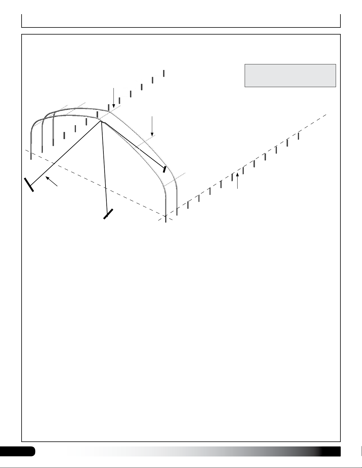
Frame Assembly
FRAME ASSEMBLY
Use the diagrams and information that follows to assemble the main frame.
ATTENTION: Rafters are heavy. Always lift rafter from two separate points to prevent damage and injury.
Examine the site to determine the best way to move the rafters into position and to set them onto the ends of each set
of ground posts. Do not set rafters into position until the ground post concrete has set.
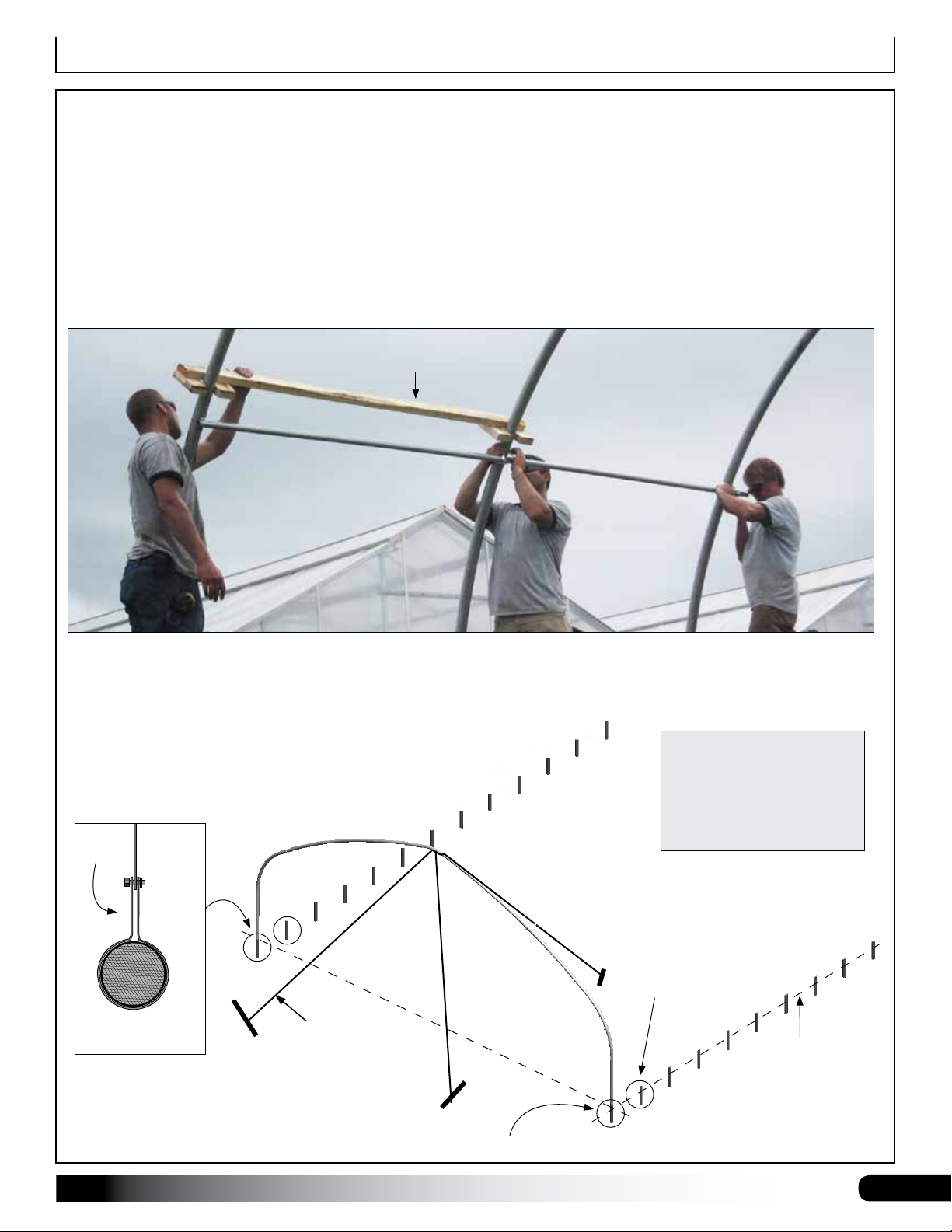
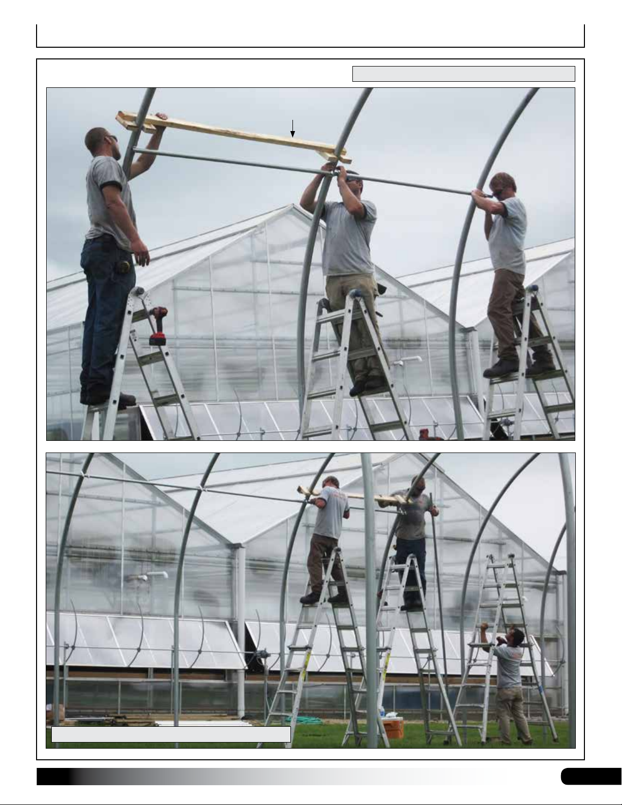
Optional, but recommended—especially for long buildings: Build a Rafter-Spacing Jig. (Customer supplies materials.)
A spacing jig saves time and helps to evenly space the rafters. Jig sets the on-center spacing of rafters. Examine the
photo below and use it to build a jig to space rafters during purlin installation. Use 2" x 4" lumber and wood fasteners.
Customer-supplied
rafter-spacing jig.
ATTENTION: Anchor the first rafter in place using bracing, rope/cable, or a lift. Do not allow the first rafter to stand
without bracing until additional rafters are set and purlins are installed.
Connect rafters to ground posts using 105370B (1/2" x 4-1/2") bolts and FALB08B nuts. Position nuts to the inside.
IMPORTANT! Slide two (2)
115480 band clamps over
each of the first two ground
posts at each end of the
frame to attach side cables
if this was not done earlier.
Add two band
clamps here.
Ground Level
TOP VIEW
Band
Clamp
End
Rafter
IMPORTANT: Plumb the end rafter before
bracing it in place and installing other rafters.
Inside
of
Frame
Rope or
Cable
Add two band clamps here.
Revision date: 03.06.19 S500_42_Wide_HT_Roll_up
15
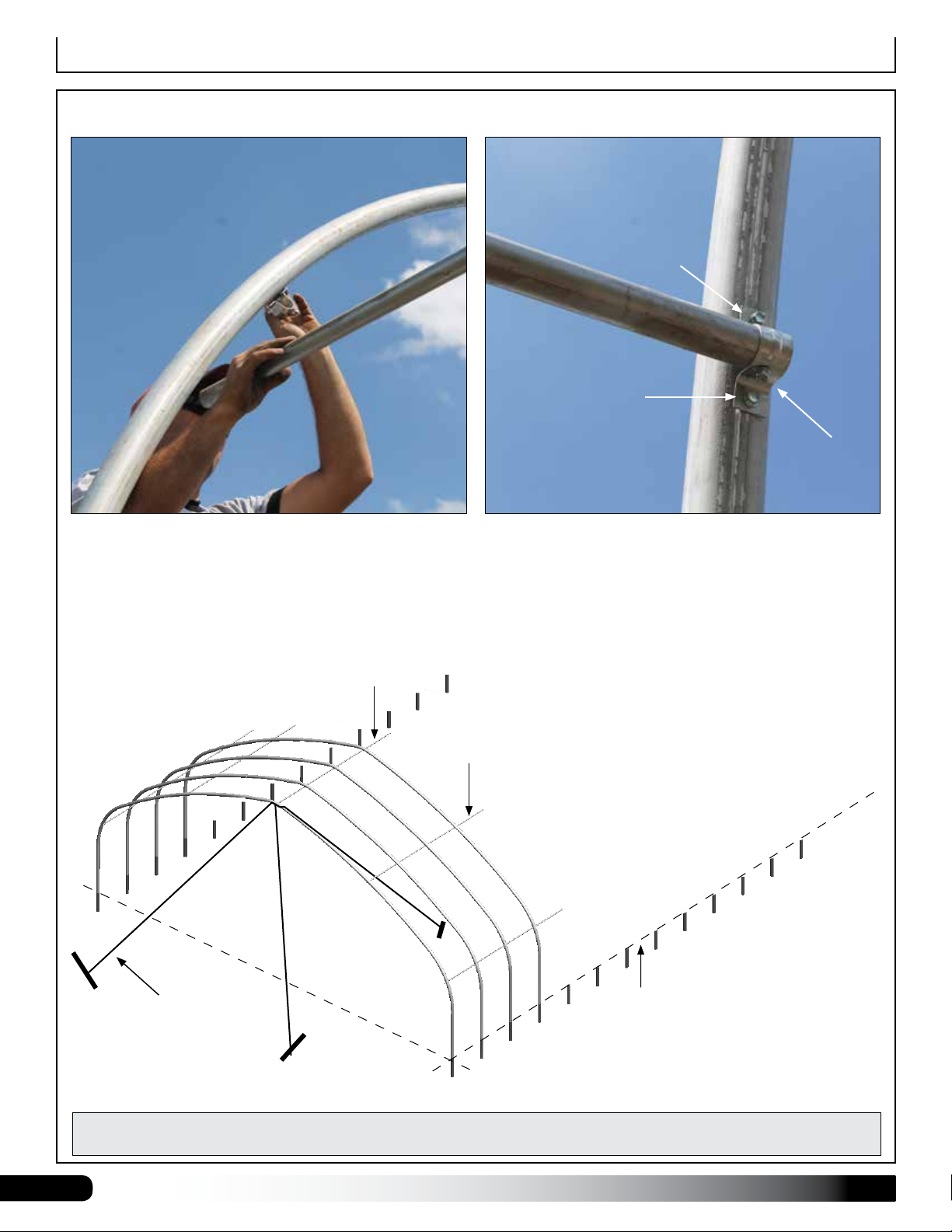
Frame Assembly
FRAME ASSEMBLY (continued)
After setting and plumbing the end rafter and bracing it in place, set the second rafter and add purlin pipes. Consult the
technical diagrams for connection details.
Ridge Purlin
Purlin Pipe
Rope or
Cable
Frame shown may differ from actual frame.
ATTENTION: Install ridge purlin
on top of the rafters when a ridge
vent will be installed.
Ground Level
After setting the first few rafters and installing the purlins, continue with the frame assembly. Loosen QH1070 brackets
as needed to install the purlin sections.
16
S500_42_Wide_HT_Roll_up Revision date: 03.06.19
Frame Assembly
FRAME ASSEMBLY (continued)
Sample frame is shown. Actual frame may differ.
Customer-supplied
rafter-spacing jig.
Purlin clamps shown may differ from actual clamps.
Revision date: 03.06.19 S500_42_Wide_HT_Roll_up
17
FRAME ASSEMBLY (continued)
End Rafter
Frame Assembly
QH1070
Pipe Strap
Purlin
Photo shows the installation of a purlin and pipe strap
at the end rafter. See Connection Details in Quick Start
section for additional information.
Actual rafter design may differ from what is shown.
Installation of purlin pipe and clamps is the same.
Ridge Purlin
FA4482B Tek
Screw
Purlin
FA4482B Tek
Screw
Secure each QH1070 pipe strap to the purlin pipe using
one Tek screw.
ATTENTION: Ensure that the on-center spacing of the
rafters is maintained throughout the frame length.
End
Rafter
FA4482B Tek
Screw
Purlin Pipe
Rope or
Cable
IMPORTANT! Secure each QH1070 pipe strap to the purlin pipe using one Tek screw. See photos above. Secure all
purlin pipe splices using a Tek screw for each splice.
18
S500_42_Wide_HT_Roll_up Revision date: 03.06.19
Ground Level

Frame Assembly
FRAME ASSEMBLY (continued)
Full Frame without Optional
Rafter Support Components
ATTENTION: Example shows a 48'
frame length. Actual frame may differ.
All purlins run perpendicular to the rafters and parallel with each other. Verify that each purlin splice is secured with a
Tek screw. Verify that each QH1070 bracket is secured to purlin pipe with a Tek screw. See photo on previous page
and all connection details diagrams in the Quick Start section.
Revision date: 03.06.19 S500_42_Wide_HT_Roll_up
19

Baseboard Installation—Recommended
BASEBOARD INSTALLATION—RECOMMENDED
Gather the parts:
• 2" x 8" treated lumber (supplied by customer). Width
of lumber can be greater.
• 1/2" carriage bolts and nuts supplied by customer.
Length depends on the thickness of the baseboard.
When properly installed, baseboard runs the length of the
frame at ground level. The baseboard is supplied by the
customer. The following procedure describes one way to
install baseboards. The size and type of the baseboard
you choose may require the use of alternative steps.
On the outside of the frame, attach the first baseboard
to the rafter using two (2) 1/2" carriage bolts and nuts.
Countersink bolt heads if carriage bolts are not used.
Continue adding baseboards to complete the first run.
Splices are made between posts as shown in the drawing
below. Use a short section of baseboard to secure
separate baseboards at a splice. See diagram below.
Repeat steps to install the second run of baseboard on
the remaining side of the frame.
NOTE: The boards should be at ground level or slightly
into grade to create a good seal between the board and
ground level. After installing the baseboards, continue
with these instructions.
Baseboard
Ground Level
Ground Posts and Baseboard
The above diagrams present examples only. Actual installation
depends on customer-supplied materials and other factors.
Ground
Level
1/2" Carriage
Outside of
Shelter
Splice
Bolts
Inside of
Shelter
5/16" Nuts
20
S500_42_Wide_HT_Roll_up Revision date: 03.06.19

Diagonal Cable Installation
Using the diagrams and photos, install diagonal cables at each end bay of the frame. Position turnbuckle either at the
top end of the cable assembly as shown in the Quick Start diagrams, or at the bottom end (for easier adjustment) as
shown in the photos on the next page.
Secure each band clamp to the rafter using a Tek screw. Install Tek screw in a location that will not contact film
cover when it is installed. Apply duct tape over band clamp on top of rafters to protect film.
PGBRKAAS01
Bracket
Shackle
Turnbuckle Cable Cable
CABLE ASSEMBLY PART NUMBERS (42' WIDE)
END BAYS (SIDEWALL) CAB25G0405
MID BAYS (ROOF) CAB25G2007
104189 Turnbuckle
AS2167
Anchor
Shackle
Complete these steps:
1. Consult the Cable Assembly table above
(also found in the Quick Start guide) and
choose a cable for the end bay sidewall
location. Verify on-center rafter spacing to
ensure correct cable is selected.
PGBRKAAS01
Bracket
PGBRKAAS01
Bracket
2. Construct a cable assembly using the
components shown in the cable diagrams
above. Ensure shackle is tighten after
installation.
3. Fully open turnbuckle. Threads of threaded
jaw should remain fully in turnbuckle body
when properly opened. See below.
Body
End of Rod
Revision date: 03.06.19 S500_42_Wide_HT_Roll_up
Photo shows installation of end bay sidewall diagonal cable
assemblies with turnbuckles at the lower end. Actual frame
design may differ from example shown.
21

Diagonal Cable Installation
CABLE ASSEMBLY AND INSTALLATION (continued)
4. For end bay sidewall cables, secure the upper band
clamp 2"- 3" below the lower side purlin run. (See
A below.)
A
2"- 3"
Band
Clamp
Lower Purlin Run
AS2167
shackle
attached
to crimped
cable end.
Steps 4 & 5
PGBRKAAS01
bracket attached
to band clamp.
A
B
Lower Purlin Run
Sample frame (above) showing installed cables. Frame
has ground posts. Dashed lines show ground level.
Steps 6 & 7
B
ATTENTION: If band clamps were not installed as
described on Pages 11 and 15, install those now.
5. Take cable assembly and attach one end to the
band clamp. Depending on preference, attach either
end to the band clamp.
6. Take remaining end of the cable assembly and use it
to judge the position of the lower band clamp. Mark
position on rafter and secure lower band clamp to
rafter using a Tek screw. See B at the right.
7. Attach cable assembly to band clamp.
8. Repeat Steps 1-7 to construct and install the
remaining seven (7) end bay sidewall cables.
9. Check to ensure each band clamp is secured to
rafter tube using a Tek screw. Tape over clamp to
protect film when it is installed.
10. Return to all cable turnbuckles and hand-tighten
until snug to remove all slack. DO NOT OVER
TIGHTEN CABLES.
11. Continue with the construction and installation of
diagonal roof cables. See next page.
Turnbuckle installed at lower end
of cable assembly and attached
directly to bracket. Actual frame
may differ from example shown.
Lower photos show attaching the PGBRKAAS01 bracket
to the installed band clamp.
Band Clamp
Secure band
clamp to pipe.
22
S500_42_Wide_HT_Roll_up Revision date: 03.06.19

Diagonal Cable Installation
In addition to the end bay sidewall diagonal cables, this frame includes mid bay roof diagonal cable assemblies.
Consult the frame connection diagrams in the Quick Start section near the back of this guide for all connection details.
See Cable Assembly table on Page 21 (and in Quick Start section) for cable part number.
PARTS TO ASSEMBLE AND INSTALL MID BAY CABLES
FAME09B
1/2" Washers
AS2167
Anchor
Shackle
FALB08B
1/2" Nuts
104189 Turnbuckle
108503
Cable
Bracket
105370B
1/2" x 4-1/2" Bolt
PROCEDURE 1: INSTALL 108503 CABLE BRACKETS
Unlike end bay sidewall diagonal cables, mid bay roof
cables attach to a 108503 angled bracket secured to
the rafter using a bolt and nut. Read and understand
the following conditions before installing the 108503
brackets. Review connection details and Side Profile
diagram for your building length in Quick Start section.
Install all 108503 cable brackets once positions are
determined.
IMPORTANT: Review all connection detail diagrams
in the Quick Start section to better understand how to
install these cable assemblies and 108503 brackets.
A
A
B
B
ATTENTION: The B locations are identical on opposite
side of frame (not shown) on same two rafters.
PROCEDURE 2: ATTACH MID BAY CABLES
Complete these steps to attach mid bay diagonal cables
to the installed 108503 angled cable brackets:
1. Consult table on Page 21 for cable part number.
Verify on-center rafter spacing to ensure correct
cable is selected.
• Standard Roof: Secure two (2) 108503 brackets —
there will be two per through-bolt connection (A) —
using the fasteners noted above. Use the pre-drilled
hole at the rafter peak.
• No Rafter Support Kit (See Page 14): If no rafter
support components are installed at the rafter
where cable bracket is attached (B), secure 108503
brackets to the rafter using the fasteners noted
above. Use the predrilled hole in rafter. Each (B)
location will have one (1) 108503 bracket attached.
• Rafter Support Kit Installed (See Page 14): If rafter
support kit components are installed, loosen nut and
bolt at each (B) location, add the 108503 bracket,
and reinstall and tighten nut.
Revision date: 03.06.19 S500_42_Wide_HT_Roll_up
2. Attach an AS2167 shackle to one end of the cable.
3. Fully open a turnbuckle and attach it to the free
end of the cable opposite the shackle. Threads of
threaded jaw should remain fully in turnbuckle body
when properly opened. See below.
End of Rod
Body
4. Move to the frame and attach cable end with shackle
to upper 108503 bracket secured to rafter (A) above.
5. Take cable end with turnbuckle and attach turnbuckle
to lower 108503 bracket (B).
6. Repeat Steps 2-5 to construct and install the three
(3) remaining mid bay roof cable assemblies.
7. Return to all turnbuckles and hand-tighten until snug
to remove all slack.
8. Continue with the next procedure.
23

Install Ribbon Board—Optional
RIBBON BOARD INSTALLATION—Optional for RollUp Sides
Gather the parts:
• 2" x 6" treated (supplied by customer). Width of
material may differ.
• 5/16" (minimum) fasteners supplied by customer to
attach boards to metal rafter pipes. Length depends
on material thickness.
The size and type of material you choose may require
the use of alternative steps. When properly installed, the
ribbon board runs the length of the frame along each
side. The ribbon board is supplied by the customer as are
the fasteners to secure board to the rafters.
The following procedure describes one way to install the
ribbon boards.
1. Mark ribbon board height along the outside of the
frame from end-to-end using a chalk line. Consult the
diagram.
Ribbon Board
2. Align board with outer edge of end rafter and attach
to the frame. Fastener heads must be flush with
board surface. Countersink if needed.
ATTENTION: Consult the photos on the next page
for additional details.
3. Continue adding boards to complete the first run.
Splices are made between rafters as shown in the
baseboard procedure. Use a short section of material
to secure the splice between separate boards.
4. Repeat steps to install the second run of ribbon
board along the other side.
5. Continue with the installation of the 111613Z144.
Customer-supplied
Ribbon Board
66" to bottom of
ribbon board.
24
Customer-Supplied
Baseboard
S500_42_Wide_HT_Roll_up Revision date: 03.06.19

Install Ribbon Board
Customer-supplied
Ribbon Board
66" to
bottom
of ribbon
board.
Photos above show ribbon board attached to the side
of an assembled frame. Example shows using 2" Tek
screws (additional purchase) to secure board to rafters.
Screw heads are countersunk below board surface to
allow for the installation of the 111613Z144. Customersupplied exterior grade 5/16" (minimum) carriage bolts
are also an option for fasteners.
Photo below shows the installed ribbon board and the installed baseboard on a sample frame.
Ribbon Board
Ground Level
Revision date: 03.06.19 S500_42_Wide_HT_Roll_up
Baseboard
25

Attach 111613Z144 Channel to Ribbon Board
Buildings with roll-up side panels require 111613Z144 for installation. The photos below
show where to install the 111613Z144.
Secure 111613Z144 to ribbon board (if present) using FAH005B (1/4" x 2") carriage
bolts, FAMF01B (1/4") fender washers, and FALB01B (1/4") nut. Install 111613Z144
flush with ends of ribbon board and end rafters. Pre-drill bolt holes using 5/16" bit. Space
fasteners at 24" on-center throughout length of building on both sides. If no ribbon
board was installed, secure directly to rafters using two Tek screws per rafter.
Installation without Optional
Clamp or hold 111613Z144 against
ribbon board. Drill a 5/16" bolt hole.
111613Z144 for
Roll-Up Sides.
Ribbon Board
Attach 111613Z144 to ribbon board
using the 1/4" fasteners noted below.
End View
FAH005B Bolt
111613Z144
5/16" Carriage
Bolt (minimum)
supplied by
customer
2" x 6"
Ribbon Board if used.
(supplied by customer)
Splice
FALB01B Nut
FALF01B Fender
Washer
Rafter Leg
or Ground
Post
Inside of
building.
ATTENTION: If a ribbon board is
not installed, attach the 111613Z144
directly to the rafters using two (2)
FA4482B Tek screws at each rafter
position. See photo.
Splice
Piece used for backer
to join two separate
sections.
Do not secure two separate sections
to the same rafter. Splice sections
between rafters and use a small
section of 111613Z144 (or other
material) as a backer. Secure using
Tek screws as shown (or wood
screws if backer is wood). Ensure
you have enough 111613Z144 before
cutting sections for backers.
26
S500_42_Wide_HT_Roll_up Revision date: 03.06.19

Optional End Frame and Panel Installation
Typically, end framing and end panels are installed before the cover is pulled onto the frame. If
your building is equipped with an end wall and end wall covering, review the instructions sent with
the end panel kit and end wall framing and proceed as instructed.
After installing the end framing and cladding, return to this guide and continue with the installation
of the main cover and roll-up sides.
Revision date: 03.06.19 S500_42_Wide_HT_Roll_up
27

Attach U-Channel (111613Z144) to End Rafters
INSTALL U-CHANNEL
Buildings with film (or 5.2 oz) covers require double u-channel attached to end rafters to secure cover. Photos show a
building with an optional end wall and roll-up panel. Additional purchase required.
Secure the 111613Z144 u-channel to top of both end rafters using FA4482 Tek screws spaced at 16" on-center. Install
flush with the outer edge of end rafter. See comments below for details about position of channel on end rafter.
After installation, continue with the Frame Check steps on the next page.
111613Z144 Aluminum
U-Channel
111613Z144
U-Channel
for cover
installation.
28
Optional Poly Carbonate
End Wall Cladding with
End Wall Frame
Ribbon Board
111613Z144
Aluminum
Channel
attached to
the top of
each end
rafter flush to
the outside
edge of the
rafter.
S500_42_Wide_HT_Roll_up Revision date: 03.06.19

Frame Check
FRAME CHECK
Inspect the frame for sharp edges or fasteners that could damage the cover during installation.
1. Verify that all frame members are properly secured and that all bolts and clamps are tight.
2. Recheck the frame assembly for sharp edges or clamps and bolts that may interfere with the installation of the
curtain. File or tape sharp edges as needed.
3. Reposition clamps and bolts as needed and tape all rafter pipe joints with duct tape to protect the cover material.
4. Verify that the main building frame is properly and adequately anchored.
5. Clear the site around the building to prepare a staging area for the cover material.
6. Continue with the cover installation steps.
ATTENTION: Before you install the cover, verify that these options if present have been installed: end wall frame,
door frames, and end wall cladding. Consult the documentation for those items and proceed as instructed. If these
items have been installed or are not present, continue with the cover installation.
Revision date: 03.06.19 S500_42_Wide_HT_Roll_up
29

Film (or 5.2 oz) Cover Installation
INSTALL MAIN COVER—SINGLE-LAYER FILM OR 5.2 OZ MATERIAL
Continue with the following procedure.
Gather the parts:
• Main cover and u-channel spring (#102198) for side and end rafter channels
• Ropes long enough to reach over the frame (provided by customer)
After attaching u-channel to end rafters and along the sides, unpack the main cover and pull into
place. Ropes or straps are typically used to pull the main cover onto and over the frame.
WARNING: To prevent damage to the cover and to prevent serious personal injury,
DO NOT attempt to install the main cover on windy or stormy days.
Complete these steps:
1. Take the cover material and position it along the base of one side of the building.
WEAR EYE
PROTECTION
WHEN
INSTALLING
SPRING WIRE!
NOTE: Unfold the cover and locate the edge.
30
S500_42_Wide_HT_Roll_up Revision date: 03.06.19

Film (or 5.2 oz) Cover Installation
2. Along the edge, clamp self-locking, duck-billed pliers to the cover material and
tie ropes or straps to the pliers.
NOTE: The ropes or straps must reach over the top of the building to the
other side. The number of ropes depends on building length; use additional
ropes spaced even throughout the length to prevent tearing the main cover
when it is pulled into place.
3. After tying ropes to the main cover, throw ropes over the building and pull cover into place.
Clamp self-locking,
duck-billed pliers along
the cover edge, tie
ropes or straps to the
pliers, and then pull
cover over the frame.
IMPORTANT: To prevent damage to the main cover during installation, use additional personnel and lifts as
needed.
4. Center cover side-to-side and end-to-end. Some covers include additional material for the width due to standard
material dimensions. This material can be removed and recycled, or it can be used by the customer.
Revision date: 03.06.19 S500_42_Wide_HT_Roll_up
31

Film (or 5.2 oz) Cover Installation
INSTALL MAIN COVER (continued)
5. Once main cover is in place and centered, begin at
the peak of one end and install the 102198 wire spring
into the channel.
ATTENTION: Ensure that enough cover material is
present to lock into the end rafter channel. Typically,
the cover material is cut longer/wider than required
to cover the building. For easier anchoring, allow
approximately 10" to extend past the edge of the end
rafter as the cover is anchored. Remove the ropes
after the cover is secure.
6. Continue down both edges of first end rafter until main
cover is secured to the first end rafter.
7. Move to the other end, pull cover tight, and repeat
steps to secure cover in end rafter channel.
8. After securing cover end-to-end, move to one side
and install the 102198 spring in the side u-channel.
Use top channel of double aluminum channel for the
main cover.
NOTE: Begin at one end of channel and work toward
the other. Maintain an even length working along the
side. Final stretching of cover takes place when last
side is secured.
9. Next, move to the remaining side, stretch the cover,
and secure it in place. Pull the cover tight as the
spring and insert spring into u-channel.
10. Trim excess cover material if desired.
ATTENTION: Allow some material to remain. This
allows easier stretching of the cover in the event that
the material expands after it is installed.
11. Continue with the installation of the curtain stabilizer
bar and roll-up sides.
WEAR EYE
PROTECTION
WHEN
INSTALLING
SPRING WIRE!
Step 5
Step 8
102197 U-Channel
32
S500_42_Wide_HT_Roll_up Revision date: 03.06.19

Curtain Stabilizer Bar Installation
CURTAIN STABILIZER BAR INSTALLATION—115287
The curtain stabilizer bar secures lower end of the roll-up side panel when it is closed (or down). Stabilizer bar is installed
just above baseboard (if present), which is attached at ground level. Secure stabilizer bar to each ground post using
FA4482 Tek screws. This component is not used when buildings are equipped with drop-down side panel option.
Center of Ground Post
115287
Baseboard
115287
Baseboard
Ground Level
Install bar as seen at the
end rafter with optional
baseboard.
Side Views
Tab
No baseboard
Tab
Ground Level
Installed bar as attached to
end rafter ground post.
GS0049
Splice sections using Tek screws
and a GS0049 splice plate.
Align stabilizer bar with
center of end rafter ground
post to begin installation.
After installing stabilizer bar and baseboard (if used), continue by installing the roll-up side panels.
Revision date: 03.06.19 S500_42_Wide_HT_Roll_up
Ground Level
33

Roll-Up Side Panel Installation
34
Stabilizer bar may differ from shown in photo.
S500_42_Wide_HT_Roll_up Revision date: 03.06.19

Roll-Up Side Panel Installation
INSTALL ROLL-UP PANELS
• Film: Single roll of 108655: Field cut length in half.
Complete these steps:
1. For film, locate the roll of 108655 film, roll it out and
fold it in half (lengthwise). Cut the film in half.
ATTENTION: Before cutting, measure film to verify
correct amount. Film typically ships 2' longer per
side (e.g., 36' building: film panel is 38' long).
2. Stretch a panel along one side of shelter and center
it end-to-end. Panel will extend beyond end rafters.
ASSEMBLE ROLL-UP SIDE PANEL CONDUIT
Gather the parts:
• Pipe 1.315'' x 75'' swaged (#131S075)
• Tek screws (#FA4482B)
The roll-up conduit assembly attaches to the bottom edge
of the roll-up panel. This assembly runs the length of the
frame and serves as the center pipe that the roll-up panel
wraps around when it is opened for ventilation.
Complete these steps to assemble the roll-up side panel
conduit.
1. Locate sections of pipe (#131S075) to assemble the
roll-up panel conduit.
2. Insert the swaged end of each pipe into the plain end
of another pipe until conduit is assembled.
3. Secure each pipe joint with a Tek screw (FA4482B)
and tape over the screw using duct tape. Construct a
conduit that is longer than the building. Conduit is cut
to length in a later procedure.
Roll-up Panel
3. Using the lower channel of the double u-channel and
wire spring (102198), secure one edge of film panel
to the u-channel.
Lower Channel of the
Double U-Channel
4. With edge secured, spread free/loose edge of panel
out so it hangs down evenly from channel. Excess
film panel can be rolled onto the roll-up conduit
during the next procedure or trimmed. Do not trim
too much off.
4. With assistance, place the assembled conduit on the
lower edge of the roll-up side film.
5. Allow 6" of pipe to extend beyond the end rafter
opposite where gearbox will be installed. Allow
approximately 8" to extend beyond the end rafter at
the gearbox end of the frame.
6. Cut the pipe to length at the gearbox end.
ATTENTION: After conduit is cut to length, remainder
of pipe is used for the remaining roll-up conduit.
Count the pipes to verify that you have enough to
complete the assembly of the remaining conduit.
Consult the Twist-of-the-Wrist Assembly procedure on
the next page for diagrams that show an assembled
roll-up side.
7. Continue with the procedure that follows to attach the
conduit to the roll-up side panel.
5. Continue with the following procedures to finish the
roll-up side panel installation.
Revision date: 03.06.19 S500_42_Wide_HT_Roll_up
35

Roll-Up Side Panel Installation
ATTACH CONDUIT TO ROLL-UP PANEL
Gather the parts:
• Assembled conduit from previous procedure
• Fabric clips #CC6212 (Divide quantity in half.)
• Tek screws (#FA4482B)
To this point, the roll-up side panel along one side is
secured to and hanging down from the double u-channel.
The assembled roll-up conduit should be positioned on the
free/lower end of roll-up panel.
1. Roll assembled conduit onto the edge of film roll-up
panel.
2. Verify the conduit is evenly positioned; using half of
the #CC6212 fabric clips and the same number of
FA4482B screws, secure the panel to the conduit.
Evenly space clips throughout length of conduit.
Roll side panels so they
wrap on the inside or
underside of the panel.
CC6212
Clips
CC6212
Fabric Clip
Ground Level
Inside View
NOTE: Twist the conduit in a direction that wraps the
panel toward the inside of the frame. This allows water
to drain off the building and roll-up panel.
3. Continue to roll the conduit until excess panel material
is wound around conduit and lower edge is positioned
at the base of frame.
4. Temporarily anchor conduit and panel to the frame or
ground to prevent the wind from lifting it away from the
frame.
5. Continue with the installation of the Twist-of-the-Wrist
components.
36
Photo above shows an assembled roll-up side panel with
gearbox. The lower end of the 102570 aluminum channel
is not anchored. Channel should float above the ground,
but below the curtain stabilizer bar. Stabilizer bar may
differ from shown in photo.
S500_42_Wide_HT_Roll_up Revision date: 03.06.19

Roll-Up Side Panel Installation
TWIST-OF-THE-WRIST ASSEMBLY
Gather the parts:
• Aluminum channel (102570) and drive handle
(102480)
• Gearbox (103496) and gearbox drive (102717)
• Mounting plate (103544), bearing (102569), and
threaded rod (FAK26)
• 3/8" nuts (FALB04B) and 3/8" washers (FAME08B)
The Twist-of-the-Wrist Assembly is designed to roll up the
side panel. The following steps describe the assembly
and its installation. Sample frame is shown.
Threaded
Rod
(FAK26)
End Rafter
Double
U-Channel
3. Select the aluminum channel, drill a 3/8" hole through
the channel approximately 2" from the end, and attach
a threaded rod using a 3/8" nut on each side of the
102570 channel.
2"
4. Position the channel along the end rafter where the
Twist-of-the-Wrist assembly will be located.
Guide
Channel
(102570)
Ground Post
or Rafter Leg
Gear Box
(103496)
Carriage
Bolt
Roll-Up Side
Conduit
Baseboard
1. Measure 1/2" in from the end of the roll-up conduit,
center-punch the location on the pipe, and drill a 5/16"
hole through the conduit.
2. Insert a tubing
adapter into the
conduit and align
the holes of the
adapter with the
1/2"
drilled holes in
the conduit.
5. Secure upper end of the channel by drilling a 3/8"
hole through end rafter and attach as shown. Lower
end of channel will "float" and is not attached.
End
Rafter
Top View
Do not allow channel to contact ground. Use position of
roll-up conduit, which is at the base of frame along the
side, to help align channel when securing it in place.
Revision date: 03.06.19 S500_42_Wide_HT_Roll_up
37

Roll-Up Side Panel Installation
TWIST-OF-THE-WRIST ASSEMBLY (continued)
6. Select the bearing bracket and attach the bearings as
needed. (In some instances, the bearings may come
already attached.) Assemble as follows if needed:
NOTE: Single bearings are attached to the sides of
the bracket and double bearings to the middle portion
of the bracket. Use 1/4" hex bolts and locknuts as
needed. Install a flat washer on both sides of each
bearing to insure proper operation of bearings and the
assembly.
7. Install the longer bolts with bearings on the side of the
bracket that has the two holes. Install these before
installing the double bearing assembles. See the
figures below.
8. For the spacers on the long bolts, insert a 5/16" nut
over each bolt. These nuts are used as spacers only.
5/16" Nut
10. Attach the Twist-of-the-Wrist gearbox to the mounting
plate using hex head bolts.
11. Using a 1/4" x 2" carriage bolt (FAH005B) and nut
(FALB01B), attach the square shaft to a tubing
adapter.
5/16" Nut
9. Slide the Twist-of-the-Wrist mounting plate over the
long bolts and secure the plate with two lock nuts.
Lock Nuts
12. Slide the square shaft through the Twist-of-the-Wrist
gearbox.
38
S500_42_Wide_HT_Roll_up Revision date: 03.06.19

Roll-Up Side Panel Installation
TWIST-OF-THE-WRIST ASSEMBLY (continued)
13. Slide the Twist-of-the-Wrist assembly onto the
aluminum channel from the ground end. (This is the
free end of the channel.)
14. Using the conduit as a guide, adjust the aluminum
channel on the threaded rod so the channel runs
parallel with the end rafter. In some instances, you
may need to trim the conduit.
15. Attach the roll-up conduit to the square shaft of
the assembly by inserting a 1/4" x 2" carriage bolt
(FAH005B) through the hole in the conduit and tubing
adapter. Tighten the nut.
INSTALL THE ANTI-BILLOW ROPES
The anti-billow rope is installed along the outside of the
frame and stretches between the ribbon board and the
baseboard. When installed correctly, the anti-billow rope
helps keep the roll-up panel in place when it is fully or
partially closed. Use the diagram as a guide and complete
the steps to install the anti-billow rope.
1. Beginning at one end rafter, take two (2) eye screws
(FA2155) and attach one to the baseboard and one to
the ribbon board. Align the FA2155 eye screws with
each other. See circles below.
ATTENTION: If a baseboard is not present to mount
the eye screws, purchase eyebolts locally to mount to
the individual rafter legs/ground posts.
16. Test the operation of the Twist-of-the-Wrist assembly
and repeat the steps for the remaining assembly.
NOTE: If cover rolls in desired direction, but you want
to turn crank in the opposite direction for the same
result, unbolt, reposition/flip gearbox, and remount it
on the same side of the mounting bracket.
17. Repeat the steps to install the remaining roll-up panel
and Twist-of-the-Wrist Assembly.
18. Once both assemblies are installed, continue with the
installation of the anti-billow rope.
FA2155 Eye
Screws
2. Using the sample diagrams as guides, move to the
next rafter and attach the eye screw to either the
baseboard or the ribbon board, depending on the
desired pattern.
3. Continue installing eye screws until reaching the other
end rafter and finish installation by repeating Step 1.
4. Take one end of the bulk roll of rope, thread it through
the eye screws, and secure the end to an eye screw.
5. Move to the other end of the rope, pull to remove
slack, and cut to length. Tie the end to the eye screw.
6. Test the roll-up panel operation and adjust rope if it
interferes with the curtain.
7. Repeat for the remaining roll-up side panel.
8. Read the shelter care and maintenance information.
Revision date: 03.06.19 S500_42_Wide_HT_Roll_up
39

Shelter Care and Maintenance
SHELTER CARE AND MAINTENANCE
Proper care and maintenance of the shelter is important.
Check the following items periodically to properly maintain
the shelter:
• Regularly check the cover to ensure that it remains
tight and in proper repair.
• Replace all damaged or broken components
immediately.
• Check connections and all fasteners to verify that they
remain tight and in good condition.
• Do not climb or stand on the building at anytime.
• Inspect the anchoring system to verify that all
components remain tight and in good condition.
• Verify that the side panel components are in good
working condition.
• Do not allow the roll-up panel to remain in the open
position for extended periods. Lower the panel
periodically to allow it to dry and for cleaning.
• Replace anti-billow rope immediately if worn or
broken.
Space below is reserved for customer notes.
• Remove debris and objects that accumulate on the
building. Use tools that will not damage the cover
when removing debris.
• Remove snow to prevent excess accumulation. Use
tools that will not damage the cover when removing
snow. Keep heated during non-growing season to
prevent snow and ice buildup.
• Check the contents of the shelter to verify that nothing
is touching the cover that could cause damage.
• If the shelter is dismantled and moved, inspect all
parts and connections before using.
• For replacement or missing parts, call 1-800-245-9881
for assistance.
NOTE: With the exception of engineered buildings,
GrowSpan™ shelters and buildings do not have any
tested loading criteria unless otherwise specified.
40
S500_42_Wide_HT_Roll_up Revision date: 03.06.19

42' Wide Frame
Quick Start Guide
Frame shown with base plates.
Ground Level
Frame length of your building may differ from what is shown.
Revision date: 03.06.19 S500_42_Wide_HT_Roll_up
Frame shown with ground posts.
41

TO STRUCTURE PEAK
19'- 9/16" GROUND LEVEL
42' Wide Rafter Prole with Grid
= 63'-10" (766")
2'- 9/16"
(GRID REPRESENTS 12" SQUARES)
1'-0"
OVER THE TOP
GROUND LEVEL
42'-0" CENTER TO CENTER OF GROUND POSTS
18'- 7/16"
42
6'-2 1/2"
5'-7 1/2"
2'-0"
S500_42_Wide_HT_Roll_up Revision date: 03.06.19

(PG500TC3514S423)
RAFTER
SPLICE
SPLICE
(PG500TC3514S422)
RAFTER
QH1070
4'
QH1070
SPLICE
6
1
3/
-7
"
8
/
5
2
-
'
4
(113367)
(PG500TC3514S425)
GROUND POST
RAFTER
Mid rafter with 115356
base plate.
Rafter Prole
(PG500TC3514S424)
RAFTER
SPLICE
(PG500TC3514S423)
RAFTER
SPLICE
QH1070
6
QH1070
(PG500TC3514S422)
RAFTER
GROUND LEVEL
ATTENTION: Use these
dimensions to position QH1070
brackets for the purlins.
1
3/
-7
4'
(113367)
(PG500TC3514S425)
"
8
/
5
2
-
'
4
SPLICE
RAFTER
GROUND POST
42'-0" CENTER TO CENTER OF GROUND POSTS
End rafter with 115355
base plate.
QH1070
Revision date: 03.06.19 S500_42_Wide_HT_Roll_up
43

ISOMETRIC VIEW
4"
115355 DETAILS
ISOMETRIC VIEW
"
3
4
1
115356 DETAILS
Rafter Layout - Base Plates
4'-0" 4'-0"
115356 115356
4"
TOP VIEW
C
4"
TOP VIEW
115356 115356
C
44
115355
115355
C
C
S500_42_Wide_HT_Roll_up Revision date: 03.06.19

Baseboard shown with
base plates.
GROUND LEVEL
36'-0"
131S075 (7) CUT TO FIT.
CENTER TO CENTER OF GROUND POSTS
ROLL-UP OR DROP DOWN CONDUIT ASSEMBLY
Side Prole - 36' Length
(131S147)
PURLINS
(131S147)
PURLINS
(131S147)
PURLINS
4'-0"
RAFTER
(TYP.)
SPACING
LATERAL PURLINS
36' 5 15 (3 PER RUN)
BUILDING LENGTH NUMBER OF PURLIN RUNS QUANTITY OF 131S147 PIPE NEEDED
ATTENTION: Baseboards, ribbon boards, and
related fasteners are supplied by the customer.
Revision date: 03.06.19 S500_42_Wide_HT_Roll_up
45

48'-0"
Baseboard shown with
base plates.
Side Prole - 48' Length
GROUND LEVEL
4'-0"
(TYP.)
RAFTER
SPACING
131S075 (9) CUT TO FIT.
CENTER TO CENTER OF GROUND POSTS
ROLL-UP OR DROP DOWN CONDUIT ASSEMBLY
LATERAL PURLINS
48' 5 20 (4 PER RUN)
46
(131S147)
PURLINS
(131S147)
PURLINS
(131S147)
PURLINS
BUILDING LENGTH NUMBER OF PURLIN RUNS QUANTITY OF 131S147 PIPE NEEDED
ATTENTION: Baseboards, ribbon boards, and
related fasteners are supplied by the customer.
S500_42_Wide_HT_Roll_up Revision date: 03.06.19

Baseboard shown with
base plates.
GROUND LEVEL
60'-0"
131S075 (11) CUT TO FIT.
CENTER TO CENTER OF GROUND POSTS
ROLL-UP OR DROP DOWN CONDUIT ASSEMBLY
Side Prole - 60' Length
(131S147)
PURLINS
Revision date: 03.06.19 S500_42_Wide_HT_Roll_up
(131S147)
PURLINS
(131S147)
PURLINS
4'-0"
RAFTER
LATERAL PURLINS
(TYP.)
SPACING
60' 5 25 (5 PER RUN)
BUILDING LENGTH NUMBER OF PURLIN RUNS QUANTITY OF 131S147 PIPE NEEDED
ATTENTION: Baseboards, ribbon boards, and
related fasteners are supplied by the customer.
47

72'-0"
Baseboard shown with
base plates.
Side Prole - 72' Length
GROUND LEVEL
131S075 (13) CUT TO FIT.
CENTER TO CENTER OF GROUND POSTS
ROLL-UP OR DROP DOWN CONDUIT ASSEMBLY
LATERAL PURLINS
4'-0"
(TYP.)
RAFTER
SPACING
72' 5 30 (6 PER RUN)
48
(131S147)
PURLINS
(131S147)
PURLINS
(131S147)
PURLINS
ATTENTION: Baseboards, ribbon boards, and
related fasteners are supplied by the customer.
BUILDING LENGTH NUMBER OF PURLIN RUNS QUANTITY OF 131S147 PIPE NEEDED
S500_42_Wide_HT_Roll_up Revision date: 03.06.19

84'-0"
ROLL-UP OR DROP DOWN CONDUIT ASSEMBLY
PURLIN
PURLIN
PURLIN
CENTER TO CENTER OF GROUND POSTS
131S075 (14) CUT TO FIT.
Baseboard shown with
base plates.
Side Prole - 84' Length
(131S147)
S
GROUND LEVEL
LATERAL PURLINS
4'-0"
(TYP.)
RAFTER
SPACING
84' 5 35 (7 PER RUN)
(131S147)
S
(131S147)
S
ATTENTION: Baseboards, ribbon boards, and
related fasteners are supplied by the customer.
BUILDING LENGTH NUMBER OF PURLIN RUNS QUANTITY OF 131S147 PIPE NEEDED
Revision date: 03.06.19 S500_42_Wide_HT_Roll_up
49

96'-0"
CENTER TO CENTER OF GROUND POSTS
131S075 (17) CUT TO FIT.
ROLL-UP OR DROP DOWN CONDUIT ASSEMBLY
Baseboard shown with
base plates.
Side Prole - 96' Length
50
GROUND LEVEL
LATERAL PURLINS
4'-0"
(TYP.)
RAFTER
SPACING
96' 5 40 (8 PER RUN)
(131S147)
(131S147)
PURLINS
PURLINS
(131S147)
ATTENTION: Baseboards, ribbon boards, and
PURLINS
related fasteners are supplied by the customer.
BUILDING LENGTH NUMBER OF PURLIN RUNS QUANTITY OF 131S147 PIPE NEEDED
S500_42_Wide_HT_Roll_up Revision date: 03.06.19

120'-0"
ROLL-UP OR DROP DOWN CONDUIT ASSEMBLY
PURLIN
PURLINS
(131S147)
PURLIN
CENTER TO CENTER OF GROUND POSTS
131S075 (20) CUT TO FIT.
Baseboard shown with
base plates.
Side Prole - 120' Length
GROUND LEVEL
LATERAL PURLINS
4'-0"
(TYP.)
RAFTER
SPACING
120' 5 50 (10 PER RUN)
(131S147)
S
(131S147)
S
ATTENTION: Baseboards, ribbon boards, and
related fasteners are supplied by the customer.
BUILDING LENGTH NUMBER OF PURLIN RUNS QUANTITY OF 131S147 PIPE NEEDED
Revision date: 03.06.19 S500_42_Wide_HT_Roll_up
51

VIEW 9
SIDE CABLE TO BASE PLATE CONNECTION
RAFTER SPLICE
CONNECTION
Connections
VIEW 8
SIDE CABLE TO PURLIN AT END RAFTER
CONNECTION
SIDE CABLE TO GROUND POST
VIEW 7A
CONNECTION
VIEW 7B
(BASE PLATE CONNECTION NOT SHOWN)
CONNECTION
VIEW 6A
(BASE PLATE CONNECTION NOT SHOWN)
VIEW 6B
RAFTER TO GROUND POST
RAFTER TO BASE PLATE CONNECTION
VIEW 5
ROOF CABLE TO PURLIN
AT MID RAFTER
CONNECTION
VIEW 4
PURLIN MID RAFTER
CONNECTION
VIEW 3
PURLIN SPLICE
CONNECTION
VIEW 2
SIDE CABLE TO PURLIN AT MID RAFTER
CONNECTION
VIEW 1
CABLE ASSEMBLY
52
VIEW 10
ROOF CABLE TO RIDGE PURLIN AT
MID RAFTER CONNECTION
VIEW 11
RIDGE PURLIN MID
RAFTER CONNECTION
VIEW 12
RIDGE PURLIN END
RAFTER CONNECTION
Ground Level
R
S500_42_Wide_HT_Roll_up Revision date: 03.06.19

PURLIN
VIEW 3
RAFTER
PURLIN
(1X) #14 X 1" TEK SCREW
PURLIN SPLICE CONNECTION
CABLE ASSEMBLY
[105370B]
[FAME09B]
[FALB08B]
VIEW 5
(1) BAND CLAMP (115480)
(1) CARR BOLT 5/16X1-1/2 (FAH317B)
(1X) #14 X 1" TEK SCREW
(1) 5/16 NUT (FALB32B)
CABLE ASSEMBLY
VIEW 2
PURLIN
RAFTER
(1X) 1/2" X 4-1/2" HEX BOLT
(1X) 1/2" WASHER
CABLE BRACKET
[108503]
(1X) 1/2" HEX NUT
ROOF CABLE TO PURLIN AT MID RAFTER CONNECTION
PGBRKAAS01
CABLE BRACKET
Frame Connection Details: Views 1 – 5
SLEEVE (TYP.)
TURNBUCKLE ATTACHED
NOTE:
TO CABLE ASSEMBLY IN FIELD.
TURNBUCKLE (JAW-JAW)
THIMBLE (TYP.)
Revision date: 03.06.19 S500_42_Wide_HT_Roll_up
CABLE
SIDE CABLE TO PURLIN AT MID RAFTER CONNECTION
PIPE STRAP
(3X) #14 X 1" TEK SCREW
PURLIN
VIEW 1
MID RAFTER
CABLE ASSEMBLY
VIEW 4
PURLIN MID RAFTER CONNECTION
53

)
(1X) #14 X 1" TEK SCREW
(1) BAND CLAMP (115480)
(1) 5/16 NUT (FALB32B)
(1) CARR BOLT 5/16X1-1/2 (FAH317B
)
)
AS2167
PGBRKAAS01
CABLE ASSEMBLY
SHACKLE (
CABLE BRACKET (
GROUND POST
(1X) #14 X 1" TEK SCREW
(1) 5/16 NUT (FALB32B)
VIEW 7A
(1) BAND CLAMP (115480)
(1) CARR BOLT 5/16X1-1/2 (FAH317B)
RAFTER
SIDE CABLE TO GROUND POST CONNECTION
PURLIN
)
PGBRKAAS01
CABLE BRACKET
(
CABLE ASSEMBLY
VIEW 8
SIDE CABLE TO PURLIN AT END RAFTER CONNECTION
(115356)
(FALB08B)
RAFTER
- (1X) 1/2" NUT
BASE PLATE
MID RAFTER
(115355)
Frame Connection Details: Views 6A – 8
RAFTER
(FALB08B)
- (1X) 1/2" NUT
(105370B)
(105370B)
- (1X) 1/2" X 4 1/2" HEX BOLT
GROUND POST
VIEW 6B
(1X) #14 X 1" TEK SCREW
RAFTER TO BASE PLATE CONNECTION
)
AS2167
CABLE ASSEMBLY
SHACKLE (
VIEW 6A
RAFTER TO GROUND POST CONNECTION
(1) BAND CLAMP (115480)
(1) CARR BOLT 5/16X1-1/2 (FAH317B)
(1) 5/16 NUT (FALB32B)
(PGBRKAAS01)
CABLE BRACKET
BASE PLATE
VIEW 7B
SIDE CABLE TO BASE PLATE CONNECTION
54
S500_42_Wide_HT_Roll_up Revision date: 03.06.19

RIDGE PURLIN END RAFTER CONNECTION
[105370B
]
RAFTER
[FAME09B]
(1X) 1/2" X 4-1/2" HEX BOLT
(1X) 1/2" WASHER
[FALB08B]
RAFTER
(1X) 1/2" HEX NUT
PURLIN
(QH1070)
(3X) #14 X 1" TEK SCREW
PIPE STRAP
VIEW 13
VIEW 10
CABLE BRACKET
[108503]
RIDGE PURLIN
[AS2167]
END RAFTER
PURLIN END RAFTER CONNECTION
ROOF CABLE TO RIDGE PURLIN AT MID RAFTER CONNECTION
SHACKLE
CABLE ASSEMBLY
RIDGE PURLIN
(QH1070)
VIEW 12
RAFTER
MID RAFTER
(3X) #14 X 1" TEK SCREW
PIPE STRAP
VIEW 9
- (1X) 1/2" X 4 1/2" HEX BOLT
- (1X) 1/2" NUT
Frame Connection Details: Views 9 – 13
RAFTER SPLICE CONNECTION
RIDGE PURLIN
(QH1070)
PIPE STRAP
(3X) #14 X 1" TEK SCREW
VIEW 11
Revision date: 03.06.19 S500_42_Wide_HT_Roll_up
MID RAFTER
RIDGE PURLIN MID RAFTER CONNECTION
55

11'-5 3/4" GROUND LEVEL TO
(115480)
(115480)
BAND CLAMP
WEB
)
ST05050D13G17S1
(
(106735)
(S20P126G14SGA)
BAND CLAMP
CROSS BEAM
(S20P07812G14SS1)
WEB TO RAFTER
VIEW 2
CONNECTION
(115480)
BAND CLAMP BAND CLAMP
)
WEB
ST09050D13G17S1
(
)
WEB
ST09050D13G17S1
(
)
CROSS BEAM
(106735)
VIEW 1
WEB TO CROSS BEAM
BAND CLAMP
VIEW 4
CROSS BEAM
CONNECTION
(S20P07812G14SS1)
CROSS BEAM
CONNECTION
GROUND LEVEL
42'-0" CENTER TO CENTER OF GROUND POSTS
NOTE: If rafter with support kit is positioned where mid bay
diagonal cables are located, use this bolt (each end) to secure
108503 cable bracket to rafter. See Page 23 and Quick Start
diagrams for additional details.
42' Rafter Prole with Optional Support Kit
56
(115480)
BAND CLAMP
(106735)
(S20P126G14SGA)
WEB
ST05050D13G17S1
BAND CLAMP
(
VIEW 3
CROSS BEAM
RAFTER TO CROSS BEAM
CONNECTION
CENTER OF CROSS BEAM
2'-0"
S500_42_Wide_HT_Roll_up Revision date: 03.06.19

CROSS BEAM CONNECTION
)
RAFTER TO CROSS BEAM CONNECTION
(1X) 5/16" X 1-1/2" GALV. CARRIAGE BOLT
115480
BAND CLAMP (
RAFTER
WEB
(1X) 5/16" GALV. NUT
WEB
(4x) 3/8" X 3" HEX BOLT
(4x) 3/8" WASHER
(4x) 3/8" LOCK WASHER
VIEW 2
WEB TO RAFTER CONNECTION
[115187]
2" SQ TUBE INSERT
CROSS BEAM
(4x) 3/8" HEX NUT
VIEW 4
Optional Support Kit—Connection Details
CROSS BEAM
(1X) #14 X 1" TEK SCREW
WEB
106735)
BAND CLAMP (
CROSS BEAM
WEB
(1X) #14 X 1" TEK SCREW
T
VIEW 1
WEB TO CROSS BEAM CONNECTION
(1x) 1/2" X 4-1/2" HEX BOLT
(1x) 1/2" LOCK WASHER
(1x) 1/2" HEX NUT
(1x) 3/8" X 1" HEX BOLT
(1x) 3/8" LOCK WASHER
RAFTER
CROSS BEAM
VIEW 3
[115189]
U-BRACKET
Revision date: 03.06.19 S500_42_Wide_HT_Roll_up
57
 Loading...