

GROWSPAN™ COLD FRAMES & GREENHOUSES
GrowSpan™ Heavy-Duty
Commercial Cold Frame
©2018 GrowSpan
All Rights Reserved. Reproduction
is prohibited without permission.
Revision date: 05.08.18
Photo may show a different but similar model.
STK# DIMENSIONS
106363 4' W x 23" H x 7'-9" L
1
GROWSPAN™ COLD FRAMES & GREENHOUSES
YOU MUST READ THIS DOCUMENT BEFORE YOU
BEGIN TO ASSEMBLE THE SHELTER.
Thank you for purchasing this Commercial cold frame.
When properly assembled and maintained, this product will
provide years of reliable service. These instructions include
helpful hints and important information needed to safely
assemble and properly maintain the cold frame. Please
read these instructions before you begin.
If you have any questions during the assembly, contact
Customer Service at 1-800-245-9881 for assistance.
SAFETY PRECAUTIONS
LOCATION
Choosing the proper location is an important step before
you begin to assemble the cold frame.
The following suggestions and precautions will help you
determine whether your selected location is the best
location.
• This cold frame has a metal frame. Never erect the
cold frame under power lines or near fuse boxes or
sources of electricity.
• Identify whether underground cables and pipes are
present before preparing the site or anchoring the
cold frame.
• Location should be away from structures that could
cause snow to drift on or around the cold frame.
• Do not position the cold frame in a place where large
loads such as snow and ice, large tree branches, or
other overhead obstacles could fall.
• Wear eye protection.
• Wear gloves when handling panels and frame parts.
• Use a portable GFCI when working with power tools
and cords.
• Do not climb on the cold frame during or after
construction.
• Provide adequate ventilation if the structure is
enclosed.
• Do not store hazardous materials in the cold frame.
ANCHORING INSTRUCTIONS
Prior to assembling this cold frame, please read the MUST
READ document included with the shipment.
WARNING: Strong winds can cause the cold frame to
shift if it is not adequately secured to the site.
The site on which the cold frame is constructed will
determine the anchoring method that is required.
Consult a professional contractor to determine the best and
safest way to anchor the frame.
Contact your sales representative at 1-800-245-9881 for
anchoring suggestions.
SITE
After choosing a location, proper preparation of the site is
essential. The following site characteristics will help ensure
the integrity of the cold frame.
• For best results, the site must be level to properly and
safely erect and anchor the cold frame.
• Drainage: Water draining off the cold frame and from
areas surrounding the site should drain away from the
site to prevent damage to the site, the cold frame, and
contents of the cold frame.
WARNING: The individuals assembling this cold frame
are responsible for designing and furnishing all
temporary bracing, shoring and support needed
during the assembly process (if applicable). For safety
reasons, those who are not familiar with recognized
construction methods and techniques must seek the
help of a qualified contractor.
WARNING: To prevent property damage and serious
personal injury, the assembled cold frame must be
anchored to the site.
2
Revision date: 05.08.18
ASSEMBLY PROCEDURE
GROWSPAN™ COLD FRAMES & GREENHOUSES
UNPACK AND IDENTIFY PARTS
Following the instructions as presented will help ensure the
proper assembly of your cold frame. Failing to follow these
steps may result in an improperly assembled and anchored
cold frame and will void all warranty and protection the
owner is entitled.
The steps outlining the assembly process are as follows:
1. Verify that all parts are included in the shipment. Notify
Customer Service for questions or concerns.
2. Read these instructions and all additional
documentation included with the shipment before you
begin assembling the cold frame.
3. Gather the tools and assistants needed to assemble
the cold frame.
4. Re-evaluate the location and site based on the
information and precautions presented in the
documentation included with the shipment.
5. Assemble the frame components in the order they are
presented in these instructions.
6. Read the Safety and the Cold Frame Care and
Maintenance information at the end of these
instructions.
The following steps will ensure that you have all the
necessary parts before you begin to assemble the cold
frame.
1. Unpack the contents of the box or boxes and place
them where you can easily inventory the shipment.
Refer to the Bill of Materials/Spec Sheets.
2. Verify that all parts listed on the Bill of Materials/Spec
Sheets are present. If anything is missing or you
have questions, consult the Pictorial Parts Guide for
clarification, or contact Customer Service.
SAFETY INFORMATION
The cover of your cold frame is heavy. Use caution
when opening and closing the cold frame cover.
ATTENTION: When open, the cover must remain secured
at all times using the support arm and wing nuts.
Wing nuts must be tight to lock the support arm is in place.
7. Complete and return all warranty information as
instructed.
REQUIRED TOOLS
The following list identifies the main tools needed to
assemble the cold frame. Additional tools and supports may
be needed depending on the location and application.
• Tape measure or measuring device
• Variable speed drill and sockets (cordless with
extra batteries works best)
• Hammers and gloves
• Blade or power tool to cut polycarbonate panels
• Metal cutting saw to cut aluminum profile
ASSEMBLY NOTE: Install Tek screws using a clutched
drill driver running approximately 750 RPM while applying
approximately 50 lbs of force.
Do not use an impact driver to install Tek screws!
WARNING! DO NOT prop the cover open! Serious
injury may occur if the prop slips out of position.
Damage to the polycarbonate panel may occur if a
prop is used.
TO PREVENT DAMAGE OR INJURY OR BOTH, DO
NOT CLIMB OR STORE ANYTHING ON THE COLD
FRAME.
ALWAYS USE THE HANDLE WHEN RAISING OR
LOWERING THE COVER.
WARNING: THIS COLD FRAME IS NOT A TOY!
NEVER ALLOW CHILDREN TO PLAY IN OR AROUND
THE COLD FRAME. TEMPERATURES INSIDE THE
COLD FRAME CAN BECOME EXTREMELY HIGH
WHEN THE COVER IS CLOSED AND THE FRAME IS
IN DIRECT SUNLIGHT.
NEVER USE THE COLD FRAME AS A SHELTER FOR
SMALL ANIMALS AND PETS.
Revision date: 05.08.18
3
GROWSPAN™ COLD FRAMES & GREENHOUSES
The following graphics and photos will help you identify the
different parts and show you how they are used.
(Some parts are not shown.)
ASSEMBLY NOTE: Install Tek screws using a clutched
drill driver running approximately 750 RPM while applying
approximately 50 lbs of force.
Do not use an impact driver to install Tek screws!
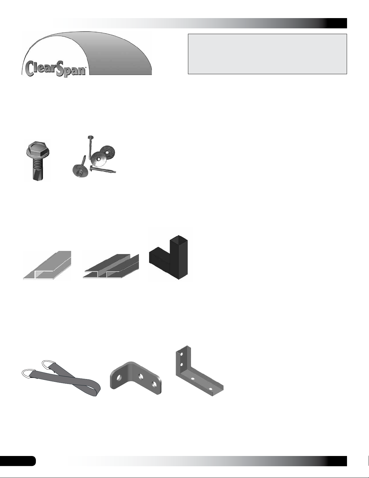
FA4472B
Tek Screw
104548
End Cap Profile
Doors/Fans/Vents
102921B & FA4474B
Tek Screws and
Neo-bonded washers
113236z096
Aluminum H-Channel
Profile
NOTE: Install center bolt
channel to the outside.
104625
2-Way Fitting
102947
D-ring Strap
4
105240
Cover Bracket
QH1330
Angle Bracket
Revision date: 05.08.18
GROWSPAN™ COLD FRAMES & GREENHOUSES
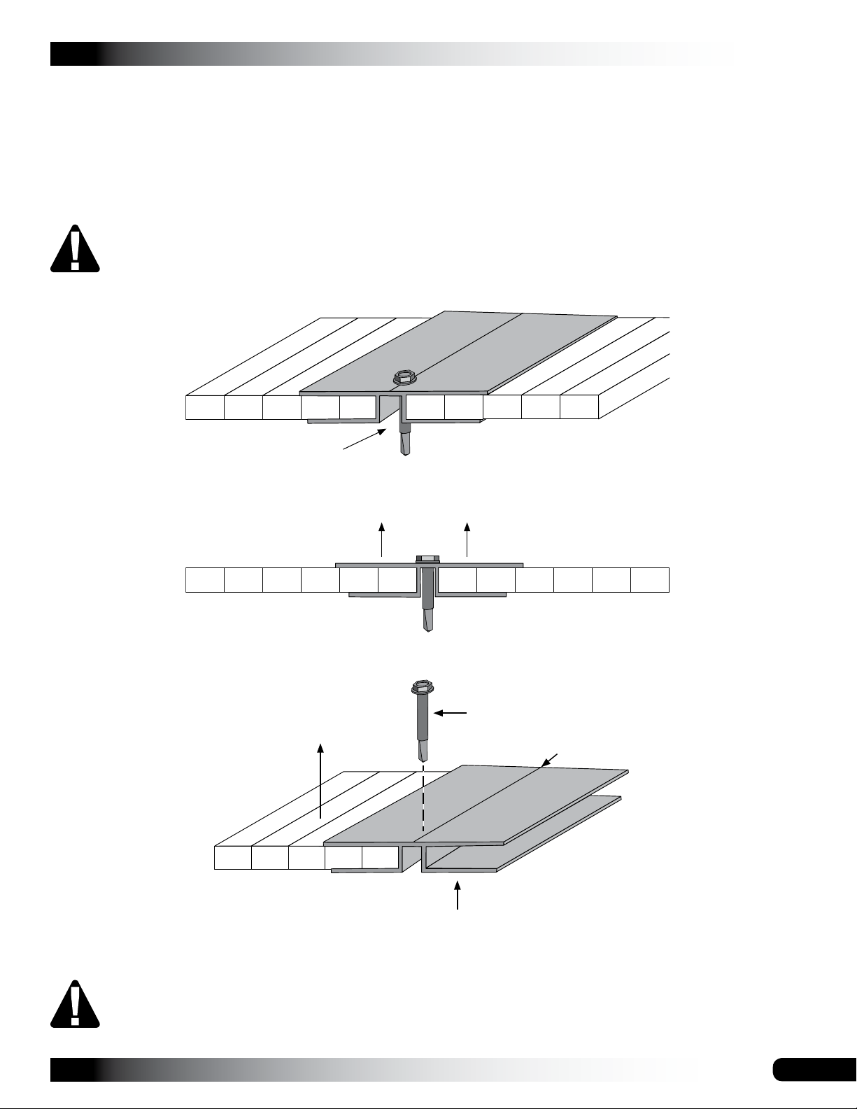
H-CHANNEL INSTALLATION INSTRUCTIONS
The new H-channel design requires installation of the at side facing out with channel side toward
the building. Some diagrams and photos in this document show installation of original H-channel with
channel side facing out. Design of new H-channel does not allow channel-side out installation.
Use the diagrams on this page to install H-channel with at side facing out.
ATTENTION: Use only 1-1/2" Tek screws to attach H-channel to building frame. Do not use
shorter screws. They will not hold. Do not use washers on Tek screws when installing
H-channel.
Flat
Side
Channel
UV-protected side
toward sun.
Flat side toward the sun.
Install 1-1/2" Tek screws through
H-channel into building frame.
Center Groove
ATTENTION: Install all twin-wall poly carbonate panels with UV-protected side toward the sun.
Revision date: 05.08.18
H-Channel
5
GROWSPAN™ COLD FRAMES & GREENHOUSES
ASSEMBLY NOTE: Install Tek screws using a clutched
drill driver running approximately 750 RPM while applying
approximately 50 lbs of force.
Do not use an impact driver to install Tek screws!
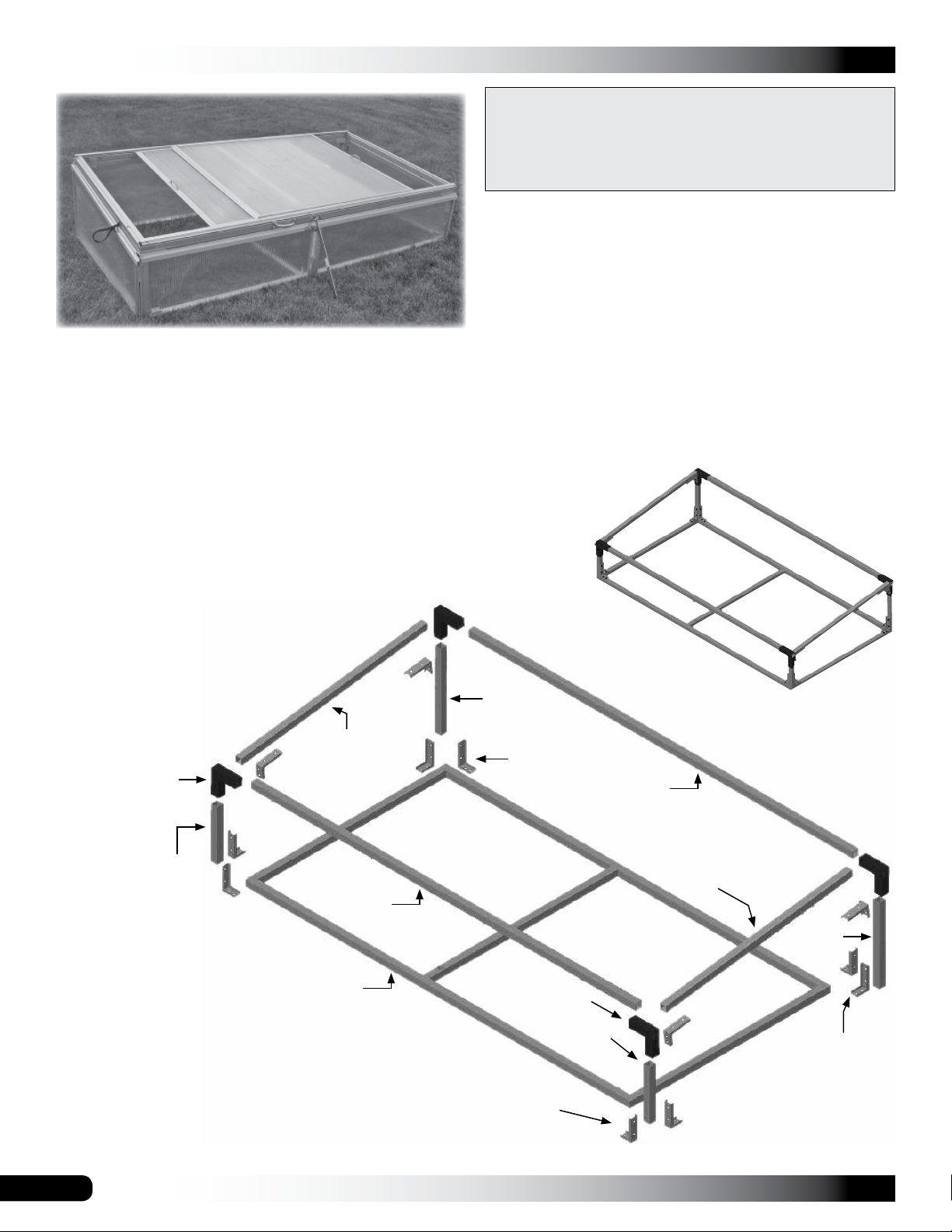
OVERVIEW
This section describes the process for assembling your
commercial cold frame. See the illustration below to identify
main parts of cold frame.
1. Locate the required parts for each assembly procedure.
2. Assemble and anchor the frame.
3. Cut and assemble the polycarbonate panels.
4. Assemble and install sliding cover panels.
5. Install safety straps and cover hardware.
S15P045
104625
GrowSpan™ Heavy-Duty
Commercial Cold Frame
S15P018
QH1330
S15P092
Assembled View
S15P012
S15P092
102923*
* A second 102923
is used for the cold
frame cover.
NOTE: Use FA4472B Tek screws to secure
the parts above during the assembly.
6
QH1330
104625
S15P012
S15P045
S15P018
QH1330
Revision date: 05.08.18
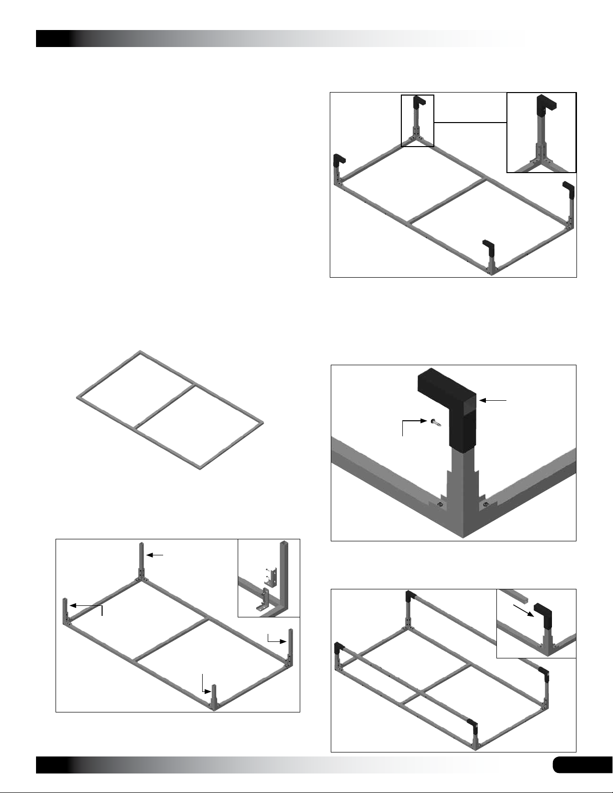
FRAME ASSEMBLY INSTRUCTIONS
After all parts are identified, assemble the frame.
NOTE: Consult the exploded frame diagram on the
previous page for part identification and clarification.
Gather the parts:
• Main frame (#102923)
• Square tubes (#S15P092 and #S15P045)
• Square tubes (#S15P018 and #S15P012)
• 2-way fittings (#104625)
• Angle brackets (#QH1330)
• Corner stakes (#105232) and hinges (#FA5030)
• Tek screws (#FA4472) and screws (#105116)
GROWSPAN™ COLD FRAMES & GREENHOUSES
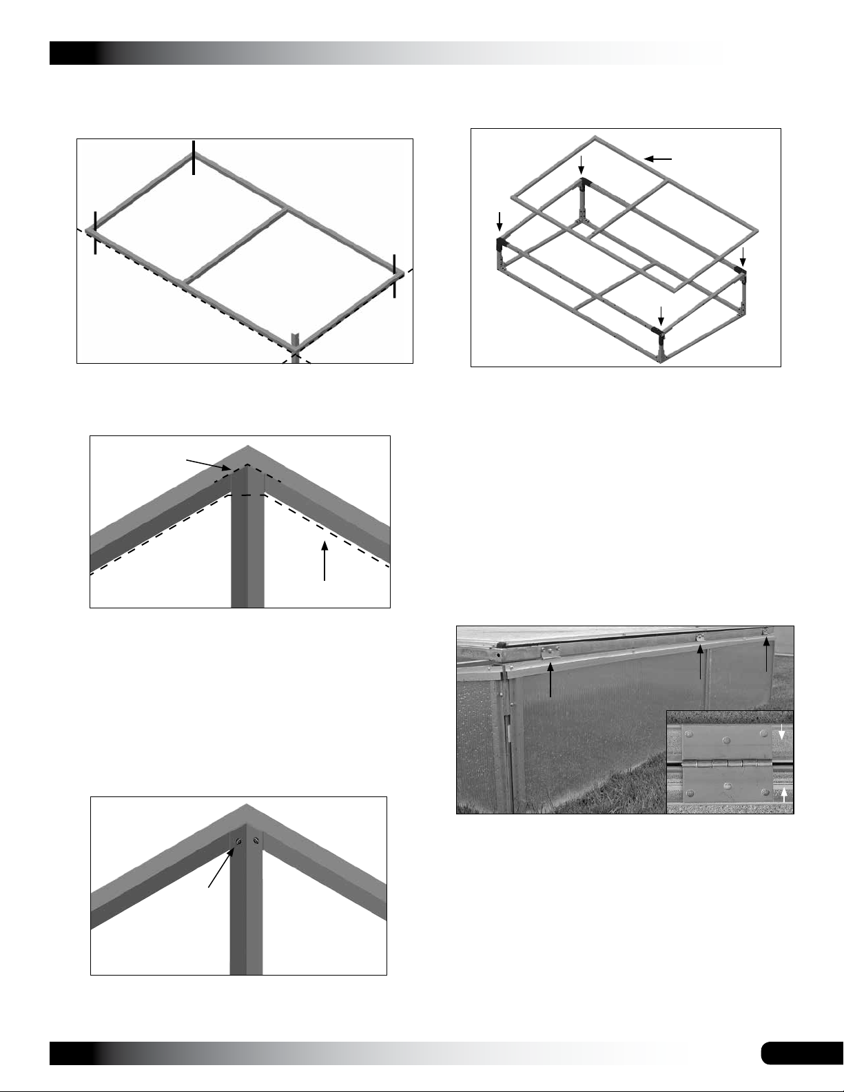
3. After all four corner tubes are in place, slide the four (4)
2-Way fittings (#104625) onto the corner frame tubes
as shown and secure with Tek screws.
Complete these steps:
1. Locate one (1) main frame component (102923),
assemble (if needed), and place it where you want to
assemble the cold frame.
2. Using the Tek screws (#FA4472) and the angle
brackets (#QH1330), attach the sidewall corner tubes.
NOTE: The 18" lengths are positioned to the back and
the 12" lengths are positioned to the front.
#S15P018
NOTE: The open end of the 2-Way fitting faces to the
outside/inside of the frame.
Install all Tek screws so that their heads do not interfere
with the installation of the polycarbonate panels. See
the following diagram.
Opening
Tek Screw
4. Locate the two (2) tubes (#S15P092) for the front and
back wall upper supports and slide these through the
openings in the 2-way fittings shown below.
#S15P012
#S15P012
#S15P018
HINT: Attach the two (2) brackets first to the square
tube and then attach the brackets and tube to the
frame.
Revision date: 05.08.18
7
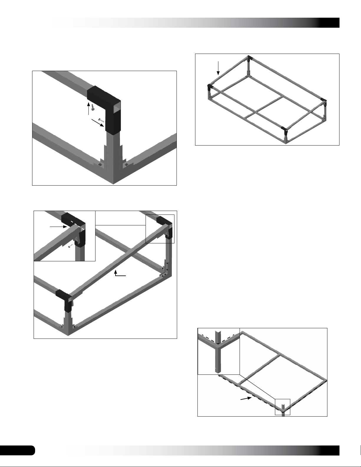
GROWSPAN™ COLD FRAMES & GREENHOUSES
FRAME ASSEMBLY INSTRUCTIONS (CONTINUED)
5. With the ends of the tubes flush to the outside of each
of the 2-Way fittings, secure the tubes in the fittings
using the Tek screws (#FA4472B).
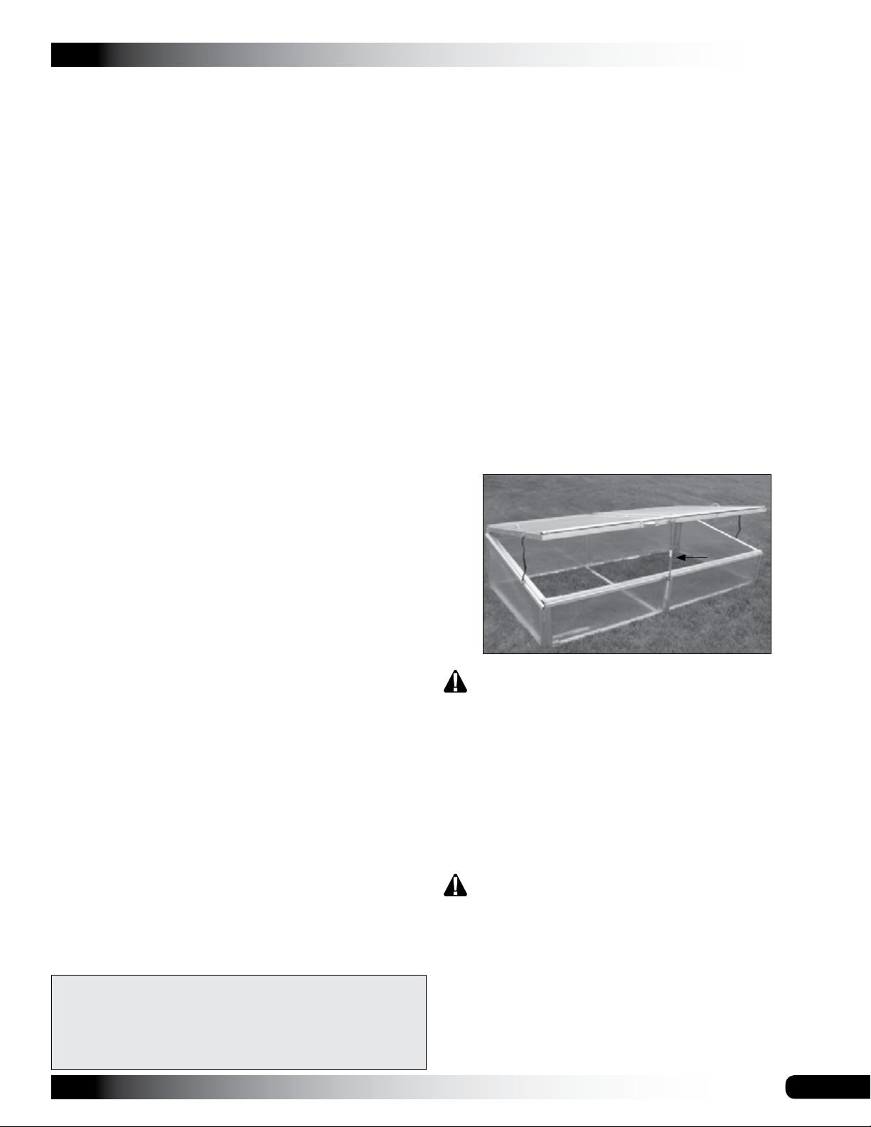
6. Locate one (1) square tube (#S15P045) for the upper
end sidewall frame and attach it as shown below.
Set Flush
NOTE: The upper sidewall tube is flush with the top of
the longer front and back frame tubes. See dashed line
in previous diagram.
Diagram shows the assembled frame without the cover.
8. Locate the four (4) angle iron corner ground stakes
(#105232) and the remaining frame assembly
(#102923) to use as a guide for driving the stakes.
NOTE: If you are positioning the cold frame on a
surface such as concrete that will not allow you to drive
ground stakes, skip this step and read the suggestions
for anchoring the cold frame.
If you plan to use the ground stakes, continue with the
next step to drive and attach the ground stakes to the
assembled frame.
# S15P045
HINT: Adjust the QH1330 brackets to fit the angle of the
sidewall. It is easiest to attach the brackets first to the
45" square tube and then to the corner tubes already
attached to the frame.
7. Repeat the steps to attach the remaining sidewall
upper support tube.
9. Position the remaining frame, which will be ultimately
used for the cold frame cover, in the location you want
the assembled cold frame.
NOTE: This frame (#102923) is used as a pattern to
position the ground stakes. It is removed after setting
the stakes.
10. Take one (1) corner stake (#105232) and drive it into
the ground as shown below. Allow a few inches of the
stake to remain above the frame.
Ground Level
ATTENTION: Position the stake to the inside of the
frame as shown above. The dashed line in the insert
diagram shows the inside edge of the frame.
8
Revision date: 05.08.18
FRAME ASSEMBLY INSTRUCTIONS (CONTINUED)
11. Repeat the steps to drive the remaining corner stakes
into the ground.
Stakes are positioned to the
inside of the frame.
Small Side
GROWSPAN™ COLD FRAMES & GREENHOUSES
16. Once the lower frame is secured to the stakes (if used),
set and center the remaining frame (#102923) on top of
the assembled cold frame.
Small square of
the cover frame
Dashed line shows
the ground level.
12. After all stakes are partially driven into the ground,
return to each stake and drive it flush to the top of the
frame.
Flush at top
Ground Level
Diagram shows the inside view and how to attach the
ground stake. Dashed line shows the ground level.
13. Once all stakes are flush as shown above, lift the frame
up and off the driven stakes.
14. With help, lift and move the assembled frame and
position the frame over the ground posts.
Front or low side
of the frame
NOTE: The cross brace of the cover frame is slightly
off center. While standing in front of the cold frame,
position the small square of the cover frame on the
left. This helps when the sliding cover panels are
assembled and installed.
17. Attach the hinges to the cover frame and the
assembled cold frame.
ATTENTION: Space hinges evenly along the cover
frame and secure using wafer-head screws (#105116).
Consult the photo below to properly position the hinges.
Photos below show the frame from the back.
Cover
Hinge (#FA5030)
Cover Frame
15. Secure each stake to the frame using two (2) Tek
screws in each corner. See the diagram below.
Tek Screws
NOTE: Tek screws can be driven through the ground
stake and into the frame if there are no pre-drilled holes
in the stakes or the holes do not line up with the frame.
Revision date: 05.08.18
Main Frame
Frame shown may differ slightly from actual frame.
NOTE: The above photo shows the assembled cold
frame from the back with an attached cover. As shown,
the aluminum profile regarding the back panel of the
cold frame is installed over the secured lower portion of
the hinge.
Panels are installed after the cover frame is attached
and the cold frame is anchored to the site.
18. Continue with anchoring information and the panel
installation instructions.
9

GROWSPAN™ COLD FRAMES & GREENHOUSES
ANCHOR THE FRAME
The following anchoring methods are recommended to
properly anchor the assembled frame.
The diagrams below illustrate two possible ways to properly
anchor the frame. The frame shown may be different. It is
used for illustration purposes only.
The parts shown in the diagrams regarding anchor systems
are not included with the cold frame. Contact Customer
Service at 1-800-245-9881 to purchase additional parts to
anchor the shelter.
CUT AND ASSEMBLE THE POLYCARBONATE PANELS
FOR THE COLD FRAME: OVERVIEW
Each polycarbonate panel is cut from the large sheets of
polycarbonate shipped with the cold frame. The following
steps describe cutting all panels. (The sliding cover panels
are assembled in the next procedure.) The general steps to
cut and install the panels are as follows:
1. Use the cut sheets near the back of these instructions
to measure and cut each panel.
2. Use the individual panels to measure and cut the
aluminum profile for each panel.
ATTENTION: Consult the diagrams (at the back of
these instructions) and the photos in this section to
properly account for the installation requirements of the
profile.
3. Install the profile on each panel.
NOTE: A small piece of tape (not included) can be
used to hold the profile in place on the panel if needed
as you attach the panels to the frame.
Anchor System for use on concrete
4. Attach the panels to the frame using screws (#105116).
CUT AND ASSEMBLE THE POLYCARBONATE PANELS
The following procedure describes cutting all panels for the
cold frame and cover. (The cover panels are set aside and
assembled and installed in the next procedure.) After the
panels are cut to the proper size, the aluminum profile is
attached to the panels for the main cold frame only.
This is the suggested method since panels adjacent to
each other are trimmed with a single piece of profile and
must be assembled together.
ATTENTION: Always install the UV-protected surface of the
polycarbonate panel to the outside of the cold frame.
The protective film that covers each panel can be peeled
away from the edges to install the profile and then
completely removed when the panels are attached to the
frame.
IMPORTANT! The cells within the polycarbonate panel
must run up and down so that moisture drains from the
panel. DO NOT install the panels with the cells running
horizontally.
Ground Anchor System *
*This system can be used in addition to the ground stakes
identified above.
ATTENTION: Ground stakes alone are not sufficient to
properly anchor the cold frame to the site.
10
USE 105116 WAFER-HEAD SCREWS TO ATTACH
ALL ALUMINUM PROFILE TO THE FRAME.
Do not allow the panels to remain in direct sunlight when
the protective film is intact. Consult the notes on the Cut
Sheet pages for additional information.
Revision date: 05.08.18

CUT AND ASSEMBLE THE POLYCARBONATE PANELS
(CONTINUED)
1. Locate the Cut Sheet for the A and B Panels and
the Panel Location Diagrams at the back of these
instructions.
ATTENTION: For the best results, read through the
panel installation procedures and consult all diagrams
and photos before cutting the panels.
Read the additional notes on the diagrams at the back
of these instructions before you continue.
2. Using the diagrams, measure, mark and cut the panels.
Mark each panel with its ID number/letter so it is
installed in the correct position on the frame and with
the UV-protected surface toward the sun.
ATTENTION: Cut Panel A and Panel B from one 4' x 8'
polycarbonate panel and set these aside to be used for
the sliding cover panels.
Cut Panels 1-Front, 2-Front, 1-Back, 2-Back and C
from the next 4' x 8' polycarbonate panel.
3. After cutting the first set of panels and marking them
with the ID, select the next polycarbonate sheet and cut
Panel D from that panel using the Cut Sheet diagrams.
NOTE: Mark the panel with its ID after. Extra panel
material has been sent in case a panel needs re-cut.
4. Using the diagrams as a guide, select a section of
aluminum profile (#104548) and a panel and cut the
profile to the correct length.
Consult the photos for Step 6 before cutting the profile
to view how to position the profile on the panels.
All profile installed in the horizontal positions on the
cold frame extends beyond the edges of the cut panels.
Refer to the photos before cutting the panels and
profile.
GROWSPAN™ COLD FRAMES & GREENHOUSES
NOTE: The profile (#104548) that runs at the tops and
bottoms of Panels 1-Front and 2-Front and 1-Back and
2-Back spans the vertical joint between the two panels.
Consult the profile installation notes on the Panel
Location Diagrams for the proper location of the
H-Channel profile (#113236Z096), which is the profile
used for the vertical seam between adjacent panels
(front and back). Attach using FA4474B Tek screws.
113236Z096
5. After cutting the profile, install the profile on the panel
edges in the proper locations.
NOTE: Use a small piece of tape (not supplied) to hold
the profile in place on the panel (if needed). After each
panel is attached to the frame as shown below, the
tape can be removed when the protective film of the
polycarbonate is removed.
Peel the protective cover from the panel. DO NOT
allow the protective film to remain on the panel in direct
sunlight. This will make the film difficult if not impossible
to remove.
6. Attach the assembled panel sections to the frame in
the locations identified on the diagrams.
The upper and lower sections of profile for the ends, back
and front panels run to the edge of the frame.
Wafer-Head Screw (#105116)
ATTENTION: This profile (#104548) is installed on all
edges of a panel unless otherwise noted. This profile
is not used for the vertical seam where two adjacent
panels are joined (front and back).
Revision date: 05.08.18
Upper Profile (Horizontal)
Vertical profile sections for the same panels run between
the horizontal lengths of profile.
11

GROWSPAN™ COLD FRAMES & GREENHOUSES
CUT AND ASSEMBLE THE POLYCARBONATE PANELS
(CONTINUED)
ASSEMBLE THE TWO (2) SLIDING PANELS FOR THE
COVER
NOTE: The vertical profile where it meets the horizontal
profile of the ends can be cut at a slight angle to match
the angle of the upper profile if desired. See black
dashed line in the previous photo.
Edge of
Frame
Horizontal profile
sections for the
front and back run
to the edge of the
frame. See solid
lines and arrows
to the right.
Vertical profile
sections run
between the
horizontal lengths.
Wafer-Head
Screw (#105116)
Horizontal Profile
Panel A and Panel B are assembled differently. Consult
the panel diagrams for each panel at the back of these
instructions for dimensions and additional information.
Assemble Panel A
1. Use the panel from Step 1 (previous procedure), the
panel diagram, and the diagram below to cut the first
profile section to the proper length.
2. Take the tube of silicone and apply a thin layer along
the edge as shown.
Profile runs parallel with the cells in the panel.
Dashed line shows the
edge of the panel.
Edge of Frame
7. After attaching all main cold frame panels, continue
by assembling and installing the sliding panels for the
cover.
Cut and attach
this section of
profile first.
Panel will slide in this direction when installed. Handle
is attached to this section of profile.
3. Install profile flush to the ends of the panel. Consult the
diagrams for the proper position.
12
Revision date: 05.08.18

ASSEMBLE THE TWO (2) SLIDING PANELS FOR THE
COVER (CONTINUED)
4. After the silicone has set, measure from the inside
edge of the first profile to the end of the panel and cut
two additional sections of profile to that length. Consult
the Panel A diagrams and the dashed lines below to
measure and position the profile.
Measure from the inside edge to the end of the panel.
5. Apply a thin film of silicone on each side of the panel
and slide a section of profile onto the panel as shown
below.
ATTENTION: Do not plug the panel cell holes with
silicone! Cells must remain open for proper venting.
GROWSPAN™ COLD FRAMES & GREENHOUSES
7. Carefully rotate the panel and repeat the steps to apply
silicone and to install the next section of profile for the
panel.
When installed correctly, the profile will appear as
shown below for Panel A.
Flat Side of Profile
NOTE: Consult the panel diagrams when installing
the profile to ensure that the UV-protected side of the
polycarbonate panel is installed toward the sun.
For Panel A, the above photo shows the top of
the panel and the UV-protected surface of the
polycarbonate.
For Panel B, the photo shows the underside of the
panel. Consult the Panel B diagrams for additional
information.
6. With the profile pressed onto the panel, use your finger
to spread the silicone along the edge of the profile
to seal the area if needed. See the dashed line in
the photo on the next page. Remove excess silicone
before it dries.
8. Allow the silicone to set and continue by assembling
Panel B.
Assemble Panel B
The steps to install the profile on Panel B are slightly
different from those of the Panel A. Consult the Panel B
diagrams for additional information.
1. Take the polycarbonate for Panel B and first install the
profile along the edges of the panel that run parallel
with the cells in the polycarbonate panel.
NOTE: Verify that the UV-protected side is in the
correct position when installing the profile. Apply
silicone and attach the profile as described in Step 1 of
the previous procedure.
Revision date: 05.08.18
13

GROWSPAN™ COLD FRAMES & GREENHOUSES
ASSEMBLE THE TWO (2) SLIDING PANELS FOR THE
COVER (CONTINUED)
2. Take the two remaining lengths of profile for Panel B
and attach these as described in Step 5 of the previous
procedure.
Measure
between the
installed profile
and cut the
remaining
profile to that
length for
Panel B.
INSTALL THE SLIDING PANELS FOR THE COVER
For clarity, the diagrams and photos in the following
procedures show the cover frame before it is attached to
the assembled cold frame. If the procedures up to this point
were followed, the cover frame has been attached to the
main cold frame and the sliding panels are prepared.
IMPORTANT NOTE: For this procedure, the small square
(or opening) of the main cover frame is positioned on the
left as seen from the front of the cold frame. The sliding
panels are assembled differently. The panels are identified
as Panel A and Panel B and must be installed as described
in the following steps.
1. With the cover frame attached and the small side
on the left as seen from the front of the frame, cut a
length of aluminum profile (#104548) to cover the long
sections of the frame. See the dashed lines in the
diagram below.
ATTENTION: Refer to the Panel B diagrams to
properly position the profile. Verify that the
UV-protected surface is facing toward the sun.
3. Allow the silicone to set before continuing.
ATTACH HANDLES TO PANEL A AND PANEL B
1. Locate a handle (#104777) and four (4) Tek screws
(#FA4472B).
2. Center the handle in the proper position on the panel
profile and install a Tek screw in each hole.
NOTE: The bottom of each Tek screw will extend
through the bottom of the profile. DO NOT
OVERTIGHTEN THE SCREWS.
3. Repeat the steps to attach the handle to the remaining
sliding cover panel.
Panel A Panel B
Profile (and tape: Step 3)
runs from end to end.
Small Side
Front of Cold Frame
2. Along the lip of the profile, mark the mounting screw
locations in 18" increments and drill a 1/4" hole in those
locations and through the profile lip.
Drill first hole 1"
in from the end.
18"
End View of Profile
Consult the diagrams above for proper handle
positions.
14
Drill 1/4" holes through
the lip at 18" spacing.
3. Cut two (2) lengths of foam tape and attach the tape
to the cover frame in the locations identified by the
dashed lines in Step 1 diagram.
NOTE: Peel the paper from the foam tape at one
end, stick the tape to the frame, and work toward the
remaining end of the frame while peeling the paper and
pressing the tape in place. For best results, position the
tape slightly inside the edges of the frame.
Revision date: 05.08.18

INSTALL THE SLIDING PANELS FOR THE COVER
(CONTINUED)
4. With the tape in place on the frame, take one piece of
profile and position it on the tape and frame as shown
below.
NOTE: The ends of the profile will be flush with the
ends of the cover frame. The edge of the profile will be
flush with the edge of the cover frame.
The profile must run evenly along the edge of the cover
frame for the sliding panels to open and close properly.
Profile must run evenly
along the edge of the
Cover Frame
frame.
GROWSPAN™ COLD FRAMES & GREENHOUSES
7. With the two (2) long sections of profile attached to the
cover frame, cut a section of felt tape and attach it to
the center cross brace of the cover frame.
Felt Tape
View as seen looking down on the cover frame.
Apply a single piece of tape on three sides of the center
cross brace.
Top
5. With the profile in position, secure it to the frame using
Tek screws (#FA4472B) inserted through the pre-drilled
holes and into the cover frame.
ATTENTION: DO NOT OVERTIGHTEN THE
SCREWS! Screws should be snug. Profile must be
allowed to adjust to the sliding panels once these are
installed.
6. Repeat the step to secure the remaining profile to the
last long edge of the cover frame. The end view below
shows the profile in the proper position.
Back of Frame
Felt Tape
Cross Brace
End View of the cross brace showing tape location.
8. Take the assembled Panel A and insert its profile into
the guide tracks of the cover frame.
NOTE: Refer to the Panel A diagrams for proper
position. Panel A is slid into the guide track from the left
side of the cover frame.
Lift the handle of the panel to allow the mounting Tek
screws to clear the outside edge of the cover frame.
The inside edge of Panel A (this is the edge without
profile) will ride on top of the felt tape attached to the
cross brace of the cover frame.
The profile installed above acts as guide tracks for the
sliding cover panels. Diagram may differ slightly from
the actual frame. White dashed line shows the tape
location.
Revision date: 05.08.18
15

GROWSPAN™ COLD FRAMES & GREENHOUSES
INSTALL THE SLIDING PANELS FOR THE COVER
(CONTINUED)
Complete the following steps to install the cover support
arm.
9. Once Panel A is in place, cut two (2) 2" sections of felt
tape and stick one on Panel A and one on Panel B in
the locations shown on the panel diagrams.
NOTE: Felt tape is used to prevent the panels from
rubbing on each other.
10. With the tape applied, take Panel B and slide it into the
guide tracks from the right side of the cover frame.
ATTENTION: When installed correctly, Panel B
overlaps the inside edge of Panel A and rides on top of
Panel A.
11. With both sliding panels installed, cut and install the
remaining two (2) lengths of profile. Install the flat side
down and against the frame. This profile runs between
the long sections of profile of the cover frame.
ATTENTION: Do not install foam tape under these last
sections of profile.
12. Check the operation of the sliding panels. If the panels
bind, loosen the mounting Tek screws of the long
sections of cover frame profile to allow the tape to
expand and retry the doors.
NOTE: When properly installed, there will be a
noticeable drag between the panels when they are slid
open and closed.
1. Locate the center of the cover frame and main cover
and mark the location.
2. Take the two (2) brackets (#105240) and attach these
as shown using Tek screws.
Center mark on
main frame.
Front Panel
NOTE: The bracket is installed on the aluminum profile
of the front panel as shown above.
Center Mark
Cover Frame
13. Continue with the installation of the support arm,
brackets, and the safety straps.
INSTALL COVER SUPPORT ARM, BRACKETS AND
SAFETY STRAPS
The cover support arm is attached to the outside of the
cover frame and to the outside of the main frame.
Support Arm (#105239)
Front Panel
3. Insert the 5/16" bolt (#FAC182R) into the bracket
attached to the cover frame and attach the support arm
to the bracket using the 5/16" wing nut.
Wing Nut (#FA1105)
Machine Screw 5/16"
(#FAC182R)
Support Arm
(#105239)
NOTE: Wing nut should remain loose enough to swing
the arm into position.
16
Revision date: 05.08.18

INSTALL COVER SUPPORT ARM, BRACKETS AND
SAFETY STRAPS (CONTINUED)
4. Flip the support arm up and install and tighten the 1/4"
nut and bolt as shown.
Bolt 1/4"
(#FAG104B)
Tighten 1/4" Nut
5. Swing the support arm into position and install the 1/4"
wing nut as shown to lock the cover in place.
GROWSPAN™ COLD FRAMES & GREENHOUSES
SAFETY STRAP INSTALLATION
The safety straps are designed to prevent the cover from
opening too far and causing injury and damage. Safety
straps are attached using Tek screws (#FA4472) and
neo-bonded washers.
WARNING: The safety straps must be installed. This
cover is designed to open for venting and watering
only. The sliding panels can be slid open to either side
to access the interior of the cold frame.
Read the Safety Information for additional precautions.
Complete the following steps to install the safety straps.
NOTE: The safety straps are attached to the outside of the
frame and cover frame along the sides to prevent damage
to plants on the inside of the frame.
1. Raise the cover and lock it in the open position using
the locking hole in the support arm as shown.
6. With all brackets tight and the support arm installed,
attach the handle to the cover frame in the desired
position using the Tek screws.
7. Check the operation of the support arm and main
cover.
8. Install the safety straps.
Revision date: 05.08.18
2. Take one safety strap with D-rings and attach it to the
outside of the cover and main frame using Tek screws
(#FA4472B) and neo-bonded washers.
17

GROWSPAN™ COLD FRAMES & GREENHOUSES
SAFETY STRAP INSTALLATION (CONTINUED)
SAFETY INFORMATION
Allow a little slack to remain in the strap so you can
easily adjust the support arm when needed.
Safety Strap
Tek Screw and
Neo-Bonded
Washer
3. Repeat the steps to install the remaining safety strap.
The cover of your cold frame is heavy. Use caution when
opening and closing the cold frame cover.
ATTENTION: When open, the cover must remain secured
at all times using the support arm and wing nuts.
Wing nuts must be tight to lock the support arm in place.
WARNING! DO NOT prop the cover open! Serious
injury may occur if the prop slips out of position.
Damage to the polycarbonate panel may occur if a
prop is used.
Photo shows properly installed safety straps.
4. Test the operation of the cover.
5. Continue by reading the safety information that follows.
• TO PREVENT DAMAGE OR INJURY OR BOTH, DO
NOT CLIMB OR STORE ANYTHING ON THE COLD
FRAME.
• SAFETY STRAPS MUST REMAIN PROPERLY
ATTACHED AT ALL TIMES. DO NOT REMOVE THE
SAFETY STRAPS!
• ALWAYS USE THE HANDLE WHEN RAISING OR
LOWERING THE COVER.
• ALWAYS LOCK THE COVER IN PLACE WHEN OPEN
USING THE SUPPORT ARM AND LOCKING WING
NUTS.
• NEVER ALLOW CHILDREN TO PLAY AROUND, ON,
OR IN THE COLD FRAME.
• COLD FRAME IS NOT DESIGNED FOR PETS OR
OTHER ANIMALS.
Continue by reading the care and maintenance information
that follows.
18
Revision date: 05.08.18

SHELTER CARE AND MAINTENANCE
Proper care and maintenance of your cold frame will help to
ensure years of service. The following items identify areas
that must be periodically checked to ensure that your cold
frame is maintained properly:
• Check the anchoring system (if applicable) to see that
all components are tight and in good repair.
• Check connections and all fasteners to verify that they
remain tight.
• Check the polycarbonate panels (if equipped) to verify
that these are in good repair.
• Do not climb or stand on the cold frame at anytime.
• DO NOT ALLOW CHILDREN OR PETS TO OCCUPY
THE INSIDE OF THE COLD FRAME!
• Remove debris and objects that can accumulate on
the cold frame. Use tools that will not damage the
polycarbonate panels when removing debris and when
trimming around the outside of the cold frame.
• Remove snow to prevent excess accumulation. Use
tools that will not damage the polycarbonate panels
when removing snow.
GROWSPAN™ COLD FRAMES & GREENHOUSES
Space below is reserved for customer notes.
• Check the contents of the shelter to verify that nothing
is touching the panels that could cause damage.
• Inspect the safety straps, support arm, and brackets to
verify that all screws and straps are tight and in good
repair.
• If the cold frame is moved, inspect all parts and
connections after moving and before use.
• For replacement or missing parts, call 1-800-245-9881
for assistance.
NOTE: With the exception of Truss Arch buildings,
GrowSpan™ shelters and greenhouses do not have any
tested loading criteria.
Revision date: 05.08.18
19

GROWSPAN™ COLD FRAMES & GREENHOUSES
QUICK START GUIDE
Commercial Cold Frame with Sliding Cover Panels
ASSEMBLY NOTE: Install Tek screws using a clutched
drill driver running approximately 750 RPM while applying
approximately 50 lbs of force.
Do not use an impact driver to install Tek screws!
20
Revision date: 05.08.18

PANEL A DIAGRAMS
Edge of Panel
Center handle and
secure with Tek
Screw (#FA4472B)
UV-Protected surface
is always installed
toward the sun.
Edge of Panel
GROWSPAN™ COLD FRAMES & GREENHOUSES
Felt Tape
44-3/4"
Handle
Top View of the Panel A
Flat Side Up
ATTENTION: Cut all profile for this
panel so that it is installed as shown
in these diagrams.
ATTENTION: Install all profile for
Panel A with the flat side up as
shown. UV-protected side of the
polycarbonate panel is always
installed toward the sun.
UV-Protected
Surface Up
Revision date: 05.08.18
DO NOT install profile along the
panel edge opposite where the
handle is attached. Panel A Only.
21

GROWSPAN™ COLD FRAMES & GREENHOUSES
PANEL B DIAGRAMS
Install felt tape
on the underside
of this length of
profile.
44-3/4"
Edge of Panel
Center handle and
secure with Tek
Screw (#FA4472B)
UV-Protected surface
is always installed
toward the sun.
Edge of Panel
Handle
Top View of the Panel B
Right-Angled Surface Up:
Flat Side Down
ATTENTION: Cut all profile for this
panel so that it is installed as shown
in these diagrams.
ATTENTION: Install all profile for
Panel B with the angled surface
up. UV-protected side of the
polycarbonate panel is always
installed toward the sun.
UV-Protected
Surface Up
22
Revision date: 05.08.18

PANEL LOCATION DIAGRAM:
TOP, FRONT AND RIGHT SIDE
GROWSPAN™ COLD FRAMES & GREENHOUSES
Dashed line shows the edge of
Panel A under Panel B.
A
1-Front
#113236Z096
NOTE: Position the H-Channel
between each long horizontal profile
section.
Install with flat side out. Use two (2)
FA4474B Tek screws.
2-Front
View shows the cold
frame from the front.
B
C
Revision date: 05.08.18
23

GROWSPAN™ COLD FRAMES & GREENHOUSES
PANEL LOCATION DIAGRAM:
BACK AND REMAINING SIDE
C
2-Back
#113236Z096
NOTE: Position the H-Channel
between each long horizontal profile
section.
Install with flat side out. Use two (2)
FA4474B Tek screws.
1-Back
View shows the cold
frame from the back.
D
24
Revision date: 05.08.18

CUT SHEETS: FRONT PANELS, "A" AND "B" PANELS
40" 48"
GROWSPAN™ COLD FRAMES & GREENHOUSES
1-Front
Read the instructions and use the diagrams
before cutting and installing the panels.
REMOVE THE PROTECTIVE FILM.
DO NOT ALLOW THE PANELS TO REMAIN IN
DIRECT SUNLIGHT WITH THE PROTECTIVE
FILM STILL IN PLACE. DOING SO WILL MAKE
THE FILM DIFFICULT IF NOT IMPOSSIBLE TO
REMOVE.
DAMAGE TO PANELS MAY OCCUR IF
STACKED IN DIRECT SUNLIGHT. PROTECT
STACKED PANELS FROM DIRECT SUNLIGHT.
2-Front
Sliding Door
Panels A & B
13-1/2"
44-3/4"
48"
ATTENTION: Install all UV-protected surfaces to the outside (toward the sun) of the cold frame.
Cut the panels as follows:
• Panel A and Panel B: one (1) 4' x 8' polycarbonate sheet
• Panels 1-Front, 2-Front, 1-Back, 2-Back, and Panel C: one (1) 4' x 8' polycarbonate sheet
• Panel D: one (1) 4' x 8' polycarbonate sheet (Part of this panel will remain in case a panel needs re-cut.)
Revision date: 05.08.18
25

GROWSPAN™ COLD FRAMES & GREENHOUSES
CUT SHEETS: BACK PANELS, "C" AND "D" PANELS
ATTENTION: Install all UV-Protected surfaces to the outside of the cold frame. See previous page to
determine which panels to cut from each 4' x 8' polycarbonate panel.
NOTE: Always read the instructions and use the diagrams before installing the panels.
40" 48"
1-Back 2-Back
C D
Dimensions for Panel C are the same as Panel D.
19-1/2"
19"
13-1/2"
45-1/2"
26
Revision date: 05.08.18

GROWSPAN™ COLD FRAMES & GREENHOUSES
Solar-Powered Opener*
(*Not included. Must be purchased separately.)
If the solar-powered opener was purchased for your commercial cold frame, use the installation instructions included
with the opener and the photos below to install the opener. Contact customer service at 1.800.245.9881 for additional
information, or to purchase the opener.
Views show the installed opener from the outside of the cold frame.
Views show the installed opener as seen from the inside of the cold frame.
ATTENTION: The support arm must remain "free" when using the solar-powered opener. To prevent damage to the cold
frame or the opener or both, DO NOT lock the cold frame lid closed after installing an opener.
Revision date: 05.08.18
27
 Loading...