

Page 1
Ventilation Systems
HS583 Curtain/Vent Machine Installation Manual
General Installation Notes:
Make sure that power is disconnected from system prior to servicing.
Installation of this equipment and related OEM equipment should be in accordance with these
instructions, OEM’s installation instructions and local codes (if applicable). Failure to follow specified
instructions may cause damage to equipment and/or personal injury or death.
Take special note of any Warnings or Safety Decals on the equipment and in manuals.
Always wear protective clothing and any applicable Personal Protective Equipment (Safety Glasses
and/or Ear Plugs) when working with the equipment.
Discarded materials, equipment and boxes should be recycled in accordance with local and national
codes.
Note: Actuator Assembly is to be wired in accordance with all applicable local and national electrical wiring codes. All
wiring sizes and fuse capacities are to be sized according to applicable electrical code specifications or other regulations.
SAFETY INSTRUCTIONS:
Read all safety messages in this manual and on equipment safety decals. Follow recommended
precautions and safe operating practices.
Ground all electrical equipment for safety.
Ground all non-current carrying metal parts to guard against electrical shock.
Always keep safety decals in good condition and replace missing or damaged decals.
Hog Slat Inc. Newton Grove, NC USA September 2014
1
Page 2
Ventilation Systems
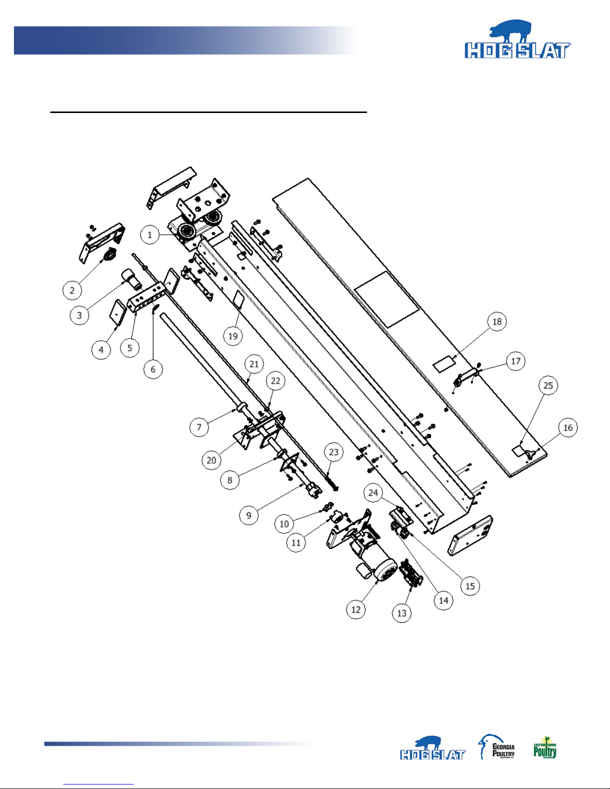
COMPONENT LAYOUT (SERVICE REPLACEMENT PARTS)
Hog Slat Inc. Newton Grove, NC USA September 2014
2
Page 3
Ventilation Systems
ITEM #
PART #
QTY PER
DESCRIPTION
1
HS583-34
3
Pulley, Cast 3-1/2" with double ball bearings
2
HS583-42
1
Bearing Flange 1" I.D
3
HS583-8-2
1
Load Nut, nylon
4
HS583-9
2
Slide, load block
5
HS583-8
1
Load block assembly with load nut & cotter pins
6 1
1 ¼” External snap ring, supplied with HS583-8-2
7
HS583-41
2
Threaded collar, seal thrust bearing nylon
8
HS583-12
1
Thrust bearing, 1” ID, D9
9
HS583-11A24
1
ACME screw, 24” machine
HS583-11A36
1
ACME screw, 36” machine
HS583-11A48
1
ACME screw, 48” machine
10
HS613
1
Spider Gear-spacer Hytrel (white) L090/L095
11
LOV38146
1
Coupling Jaw L095 5/8" bore with keyway
12
HS9050
1
Motor 1/8 HP, 115V AC, 60 Hz, 1.9A FL, 28RPM
HS9051
1
Motor 1/8 HP 230V AC, 50/60Hz, 0.75/0.90A FL, 24/29 RPM
HS9052
1
Motor 1/8 HP, 115V AC, 60 Hz, 1.65A FL, 16RPM
13
HS583-31
1
Switch assembly with (6) EL1135 micro switches
14
EL1001
1
Switch, Toggle SPDT , 10A @ 250 Volt, CTR OFF
15
EL1005
1
Switch, Toggle DPDT , 10A @ 250 Volt, CTR OFF
16
HS612
1
Knob, tri-handle, ¼-20 insert
17
HS583-45
1
Handle, Front door
18
HSLABEL-084
1
Label, “Caution Automatic Equipment”
19
HSLABEL-083
2
Label, “Warning Moving Parts”
20
HSLABEL-087
1
Label, “Grease Location”
21
HS583-27-24
1
Limit rod, 24” machine
HS583-27-36
1
Limit rod, 36” machine
HS583-27-48
1
Limit rod, 48” machine
22
HS583-28
2
Collar, steel 3/8'' w/ set screw
23
HS583-29
2
Spring, limit rod
24
EL1083
2
Rubber cover, toggle switch
25
HSLABEL-008
1
Label, Warning-Shock Hazard
Hog Slat Inc. Newton Grove, NC USA September 2014
3
Page 4
Ventilation Systems
15 & 28
4,000 lbs
2,000 lbs
1,000 lbs
60
2,000 lbs
1,000 lbs
500 lbs
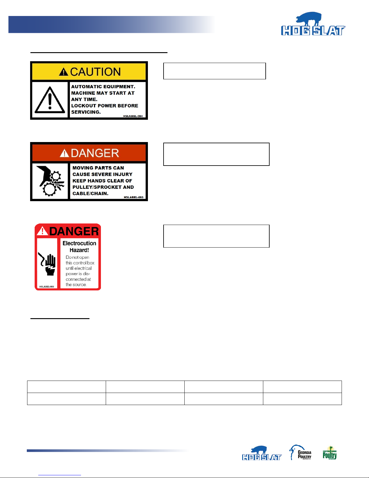
Located on front door of machine
Located on side of cabinet near
cable/chain exits.
Located at bottom of front door
SAFETY DECALS AND WARNING LABELS
near removal point.
SPECIFICATIONS:
Maximum Load: Ratio : Machine travel : vent/ curtain travel
Example: 2:1 = 2” machine travel : 1” vent/curtain travel
Refer to Figures 6 and 7
RPM 2:1 pulley ratio 1:1 pulley ratio 1:2 pulley ratio
Hog Slat Inc. Newton Grove, NC USA September 2014
4
Page 5
Ventilation Systems
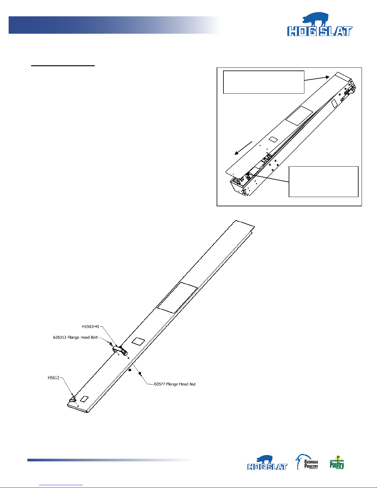
Door slides under lip at
top of machine
Lift up from bottom
to remove.
UNPACKING UNIT
Remove front cabinet door.
Packaged inside cabinet chassis:
1. HS583-50 Hardware Kit
a. Front cabinet door hardware
i. HS583-45 Handle
ii. (2) 605013 Flange head bolts
iii. (2) 60577 Flange nuts
iv. HS612 Tri-handle knob
b. Machine mounting hardware
i. (1) 3/8” x 3” Lag bolt
ii. (6) 3/8” x 2” lag bolts
iii. (2) 61646 liquid tight connectors
2. Installation manual
Assembly of Cabinet door with hardware supplied.
and slide door down
HS612 Tri-Handle Knob installs over threaded stud when cabinet door is placed on machine.
Hog Slat Inc. Newton Grove, NC USA September 2014
5
Page 6
Ventilation Systems
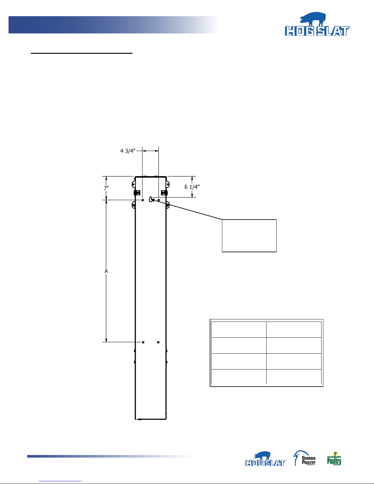
Keyhole
location
MODEL LENGTH
“A”
24”
30 3/8”
36”
42 3/8”
48”
54 3/8”
INSTALLATION / OPERATION
1. The HS583 Curtain/Vent machine is equipped with a key hole slot for easy installation as well as
(6) locations to secure unit to a wall.
2. Install (1) 3/8” X 3” Lag bolt (supplied) in the wall of the building in the desired location leaving
bolt out approximately ¼”. Lag bolt location to be center line of the machine and installed 6 1/4”
below the height of the top of the machine. Allow a minimum of 1” clearance above machine
from any structure in order to provide adequate clearance for hanging machine on keyhole lag
bolt.
3. Hang machine on bolt aligning keyhole slot located near top of the machine. (Figure 1)
mounting
Figure 1
Hog Slat Inc. Newton Grove, NC USA September 2014
6
Page 7
Ventilation Systems
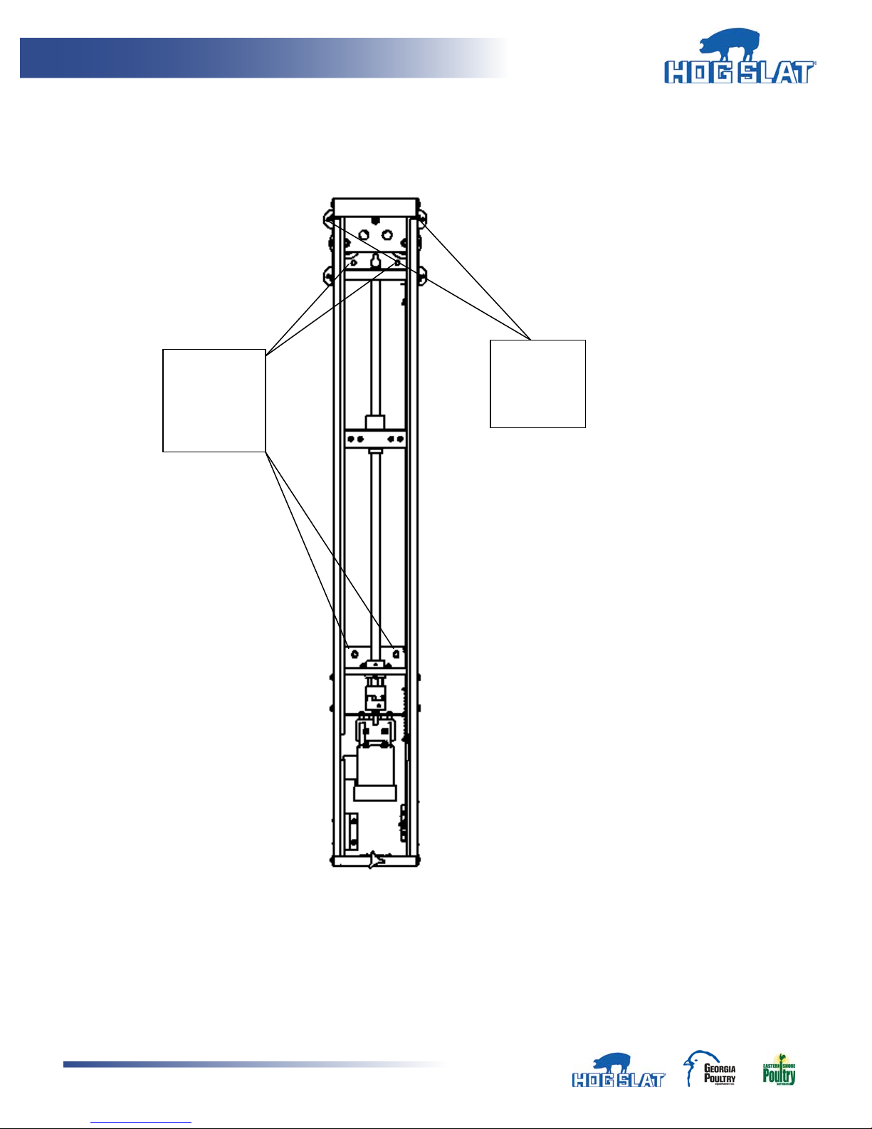
(4) Inside
(2) External
4. DO NOT OPERATE MACHINE while hanging on this bolt. Level machine and secure machine
using 3/8” x 2” Lag bolts (supplied) in the (6) mounting locations. (Figure 2)
chassis
mounting
locations
Mounting
Locations
5. When connecting cables, the load nut should be near the “Closed” position to allow enough
cable for manual winch connection.
Hog Slat Inc. Newton Grove, NC USA September 2014
7
Figure 2
Page 8
Ventilation Systems
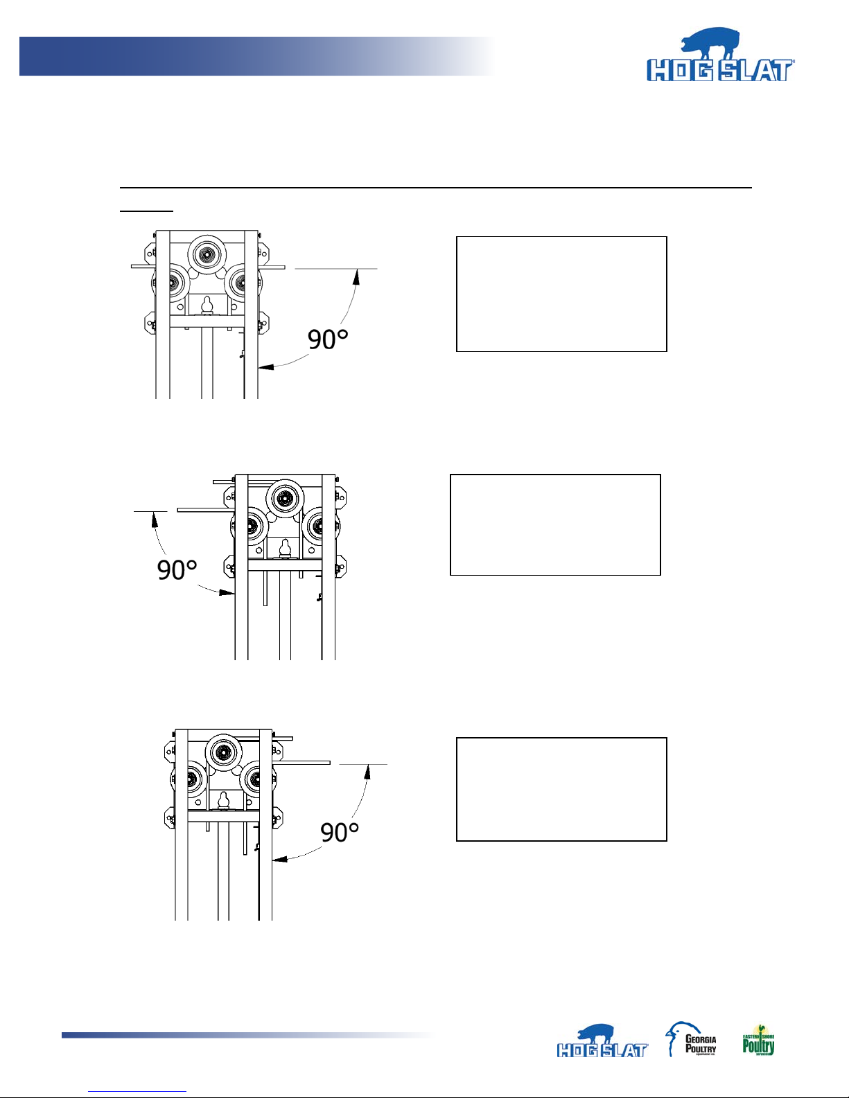
One machine used to pull two
One machine used to pull
One machine used to pull
6. Run cable ends through side of machine around pulley down to the load block. Route cables
around pulleys as shown in below figures that best suits the application.
7. Cables should exit 90 Degrees to cabinet side to ensure even load on both sides of load block.
Changing the exit angle will change force distribution on load block resulting in shorter load
nut life.
curtains from both sides, loop
cable around pulleys.
(Figure 3)
Figure 3
Figure 4
curtain from LEFT side, loop
cable around pulleys.
(Figure 4)
curtain from RIGHT side, loop
cable around pulleys.
(Figure 5)
Figure 5
Hog Slat Inc. Newton Grove, NC USA September 2014
8
Page 9
Ventilation Systems
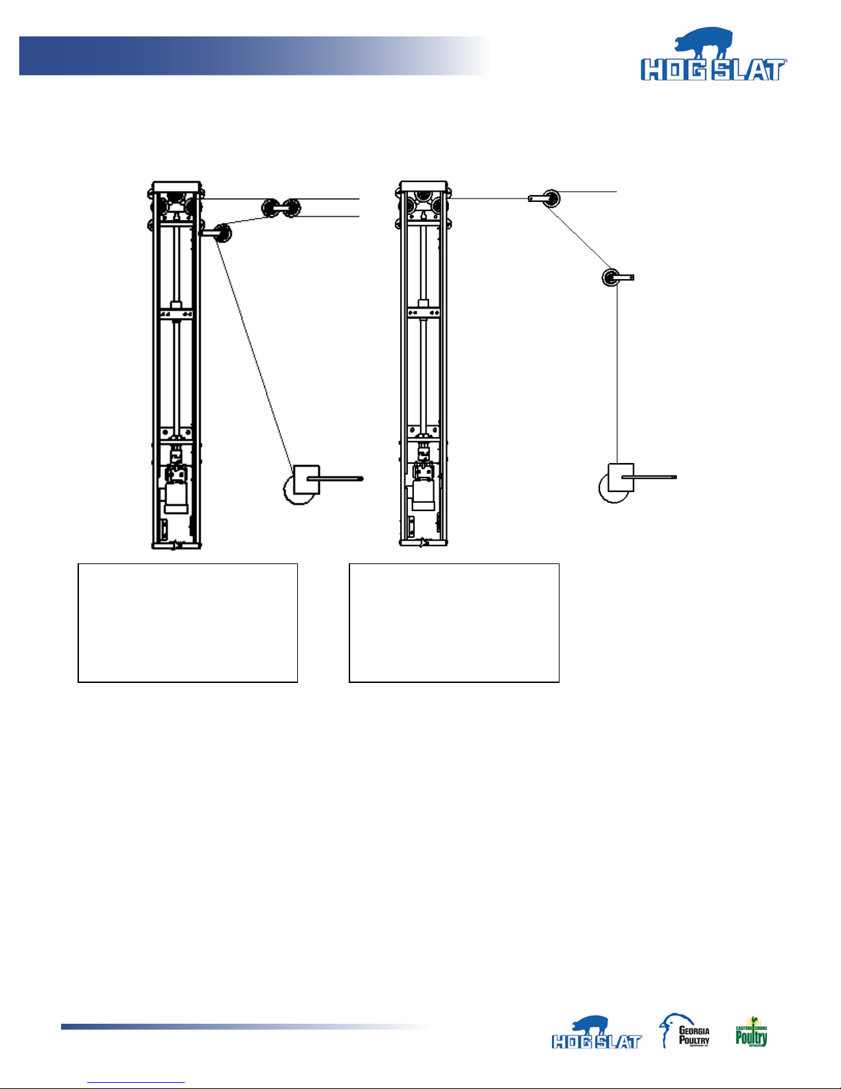
Pulley arrangement for 1:1
Pulley arrangement for 1:2
8. Install corner brackets, through wall brackets and hand winch. Use bearing supported pulleys on
any pulley that rotates during operation of machine. Figures below show examples of external
cabling and hand winch location.
ratio. For each 1 inch travel of
the machine there is 1 inch
travel of the curtain. (Figure 6)
ratio. For each 1 inch travel of
the machine there is 2 inch
travel of the curtain. (Figure 7)
Figure 7
Hog Slat Inc. Newton Grove, NC USA September 2014
9
Page 10
Ventilation Systems
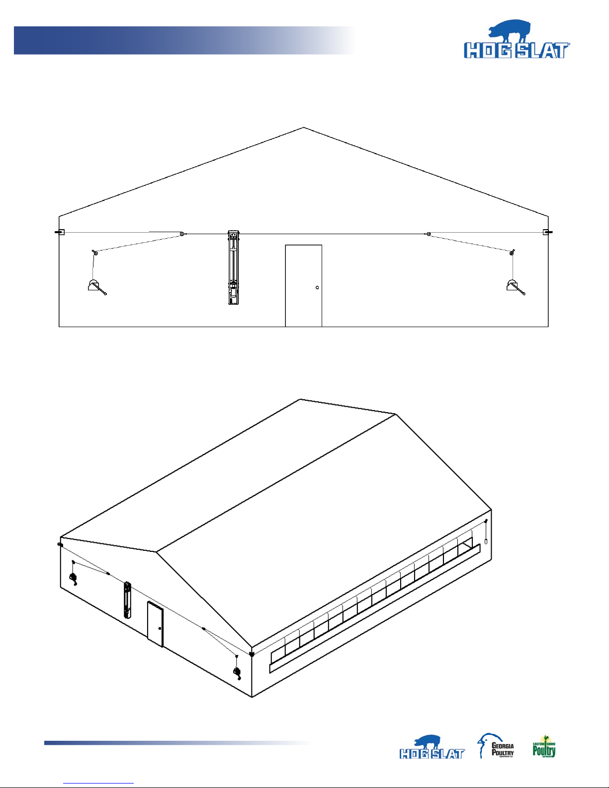
Outside Endwall Mount – Curtains
1:2 Ratio
Figure 8
Figure 9
Hog Slat Inc. Newton Grove, NC USA September 2014
10
Page 11
Ventilation Systems
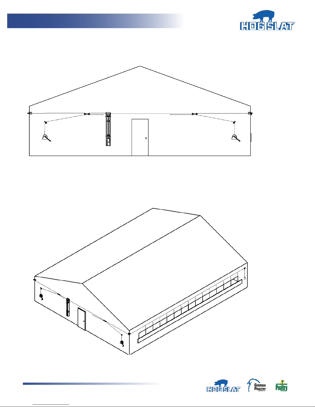
Outside Endwall Mount – Curtains
1:1 Ratio
Figure 10
Figure 11
Hog Slat Inc. Newton Grove, NC USA September 2014
11
Page 12
Ventilation Systems
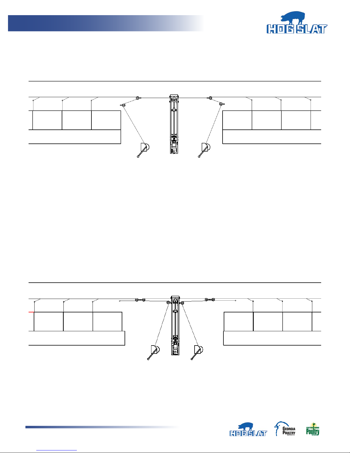
Outside of building, on one side, center mount - Curtains
1:2 Ratio
Figure 12
1:1 Ratio
Figure 13
Hog Slat Inc. Newton Grove, NC USA September 2014
12
Page 13
Ventilation Systems
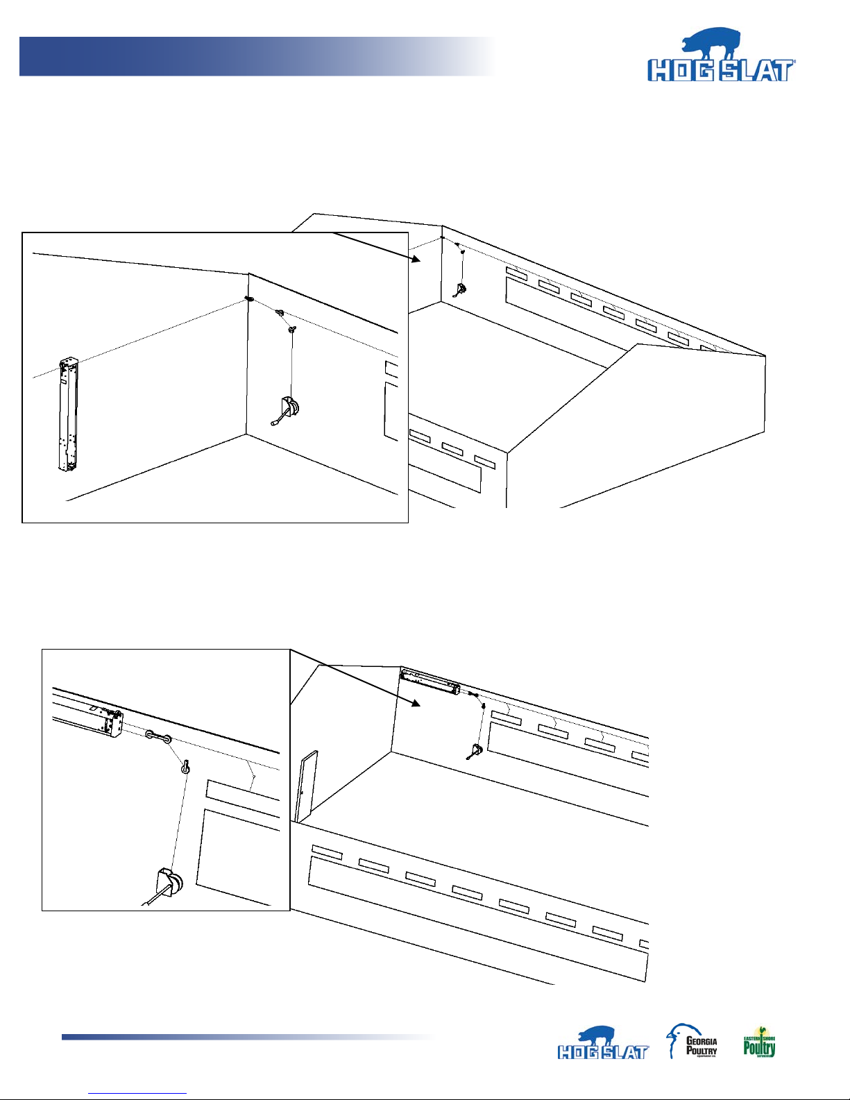
Inside Endwall Mount – Vent Doors
1:2 Ratio
Figure 14
Inside Sidewall Mount – Vent Doors
1:1 Ratio
Figure 15
Hog Slat Inc. Newton Grove, NC USA September 2014
13
Page 14
Ventilation Systems
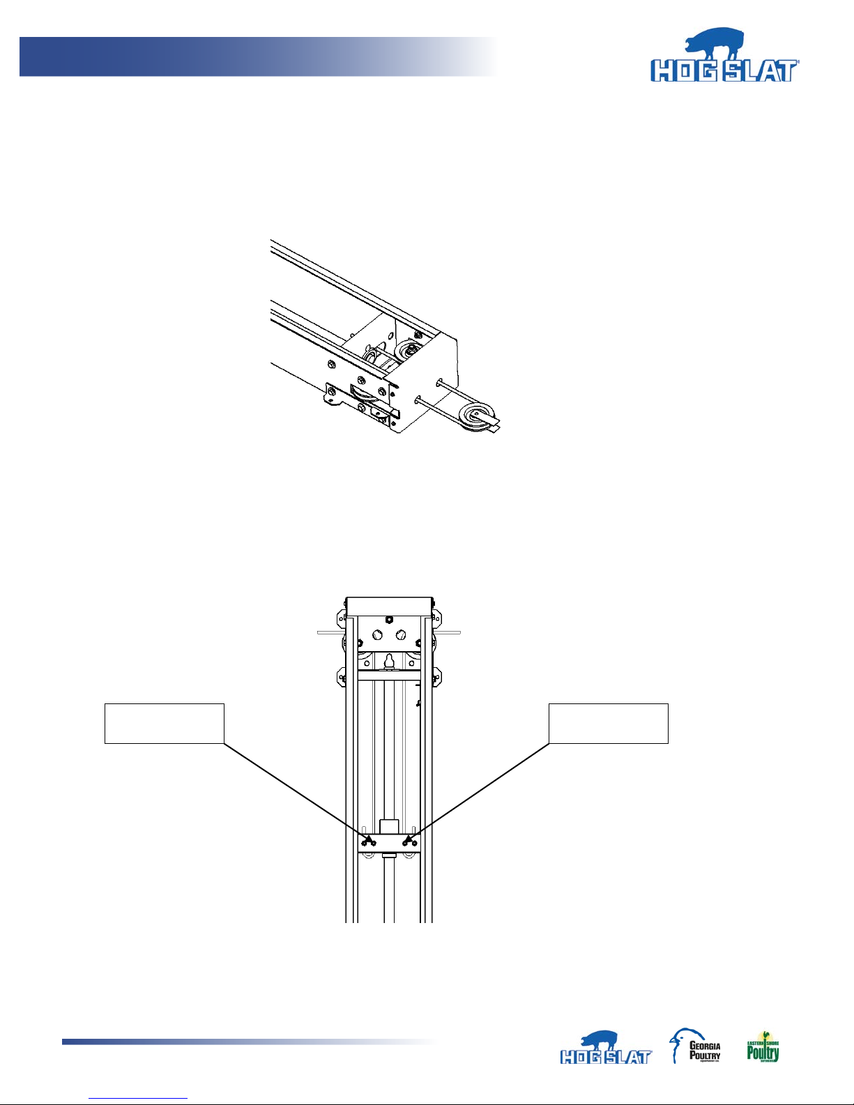
SET SCREWS
SET SCREWS
9. If mounting machine horizontally in order to pull cables straight from end of machine, remove (2)
plastic plugs found at top of machine to access pre-punch holes for routing cables. Loop cable
around bearing supported pulley to ensure even load distribution on load block. Use 3 ½”
diameter V-groove pulley to maintain proper cable spacing. (Figure 16)
Figure 16
10. To secure cable to load block, run cable through hole nearest the center in load block, then loop
back up through the outboard hole. Tighten all set-screws. (Figure 17)
Figure 17
Hog Slat Inc. Newton Grove, NC USA September 2014
14
Page 15
Ventilation Systems
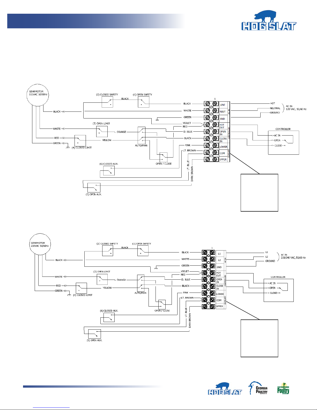
Auxiliary
Auxiliary
11. Connect wiring to machine per (Figure 18A or 18B) depending upon input voltage. All wiring
must be done in accordance to national and local electrical codes.
HS583 WIRING DIAGRAM – 115V, 60 Hz
HS583 WIRING DIAGRAM – 230V, 50/60 Hz
Figure 18A
Figure 18B
outputs are
Normally
Open
outputs are
Normally
Open
Hog Slat Inc. Newton Grove, NC USA September 2014
15
Page 16
Ventilation Systems
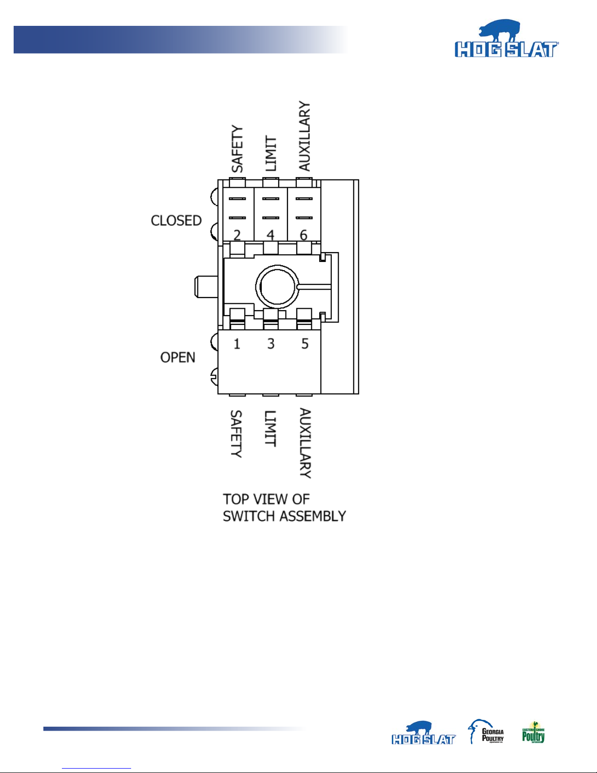
LIMIT SWITCH ASSEMBLY, SWITCH LAYOUT
Hog Slat Inc. Newton Grove, NC USA September 2014
16
Figure 19
Page 17
Ventilation Systems
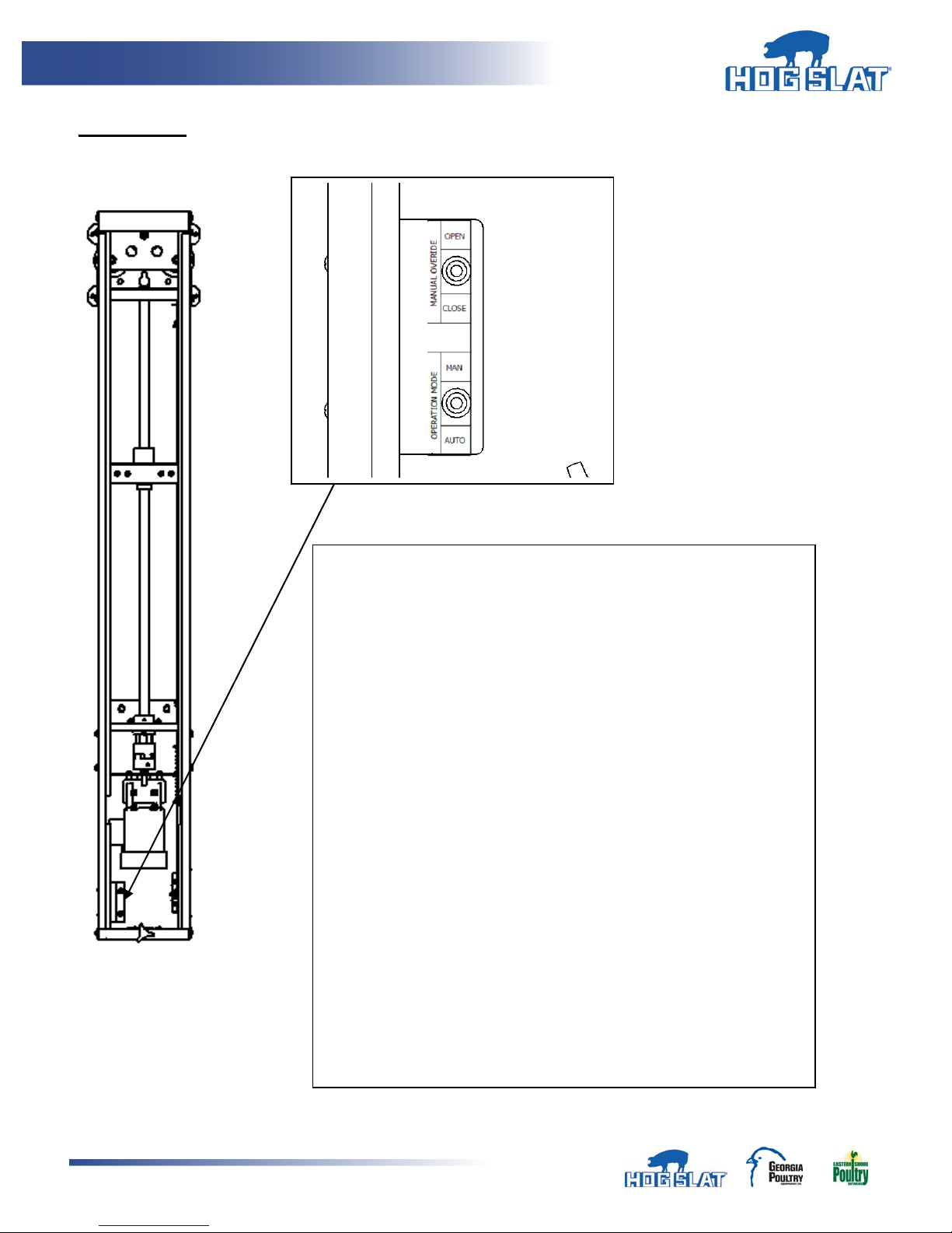
“Operation Mode” Switch
OPERATION
Figure 20
Up – Manual Mode
Center - OFF
Down - Auto Mode
“Manual Override” Switch (only functions if “Operation Mode”
switch is in “Manual Mode”)
Up - “Open” operation
Center - OFF
Down - “Close” operation
To operate machine in Auto mode for vent control: set “Operation
Mode” to “Auto”. In this position the machine will be controlled by
the ventilation controller.
Hog Slat Inc. Newton Grove, NC USA September 2014
17
Page 18
Ventilation Systems
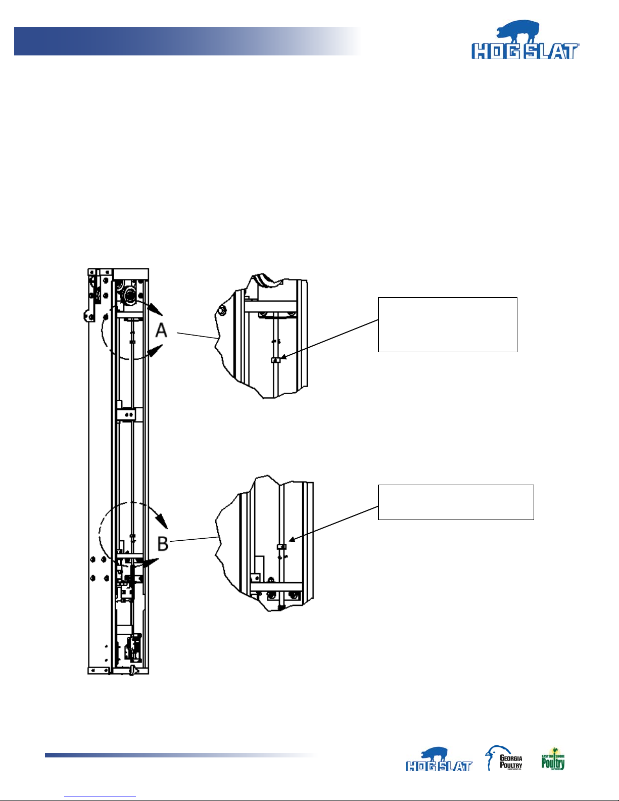
Upper Limit lock collar.
Lower Limit lock collar. Adjust
for “CLOSED” set point
12. Controller set-up and limit rod adjustment is done by locating (2) lock collars located on limit rod.
There is an upper and lower lock collar secured by 3/32” set screw. There are cotter pins
permanently installed to set absolute limit of machine in case of slippage or failure of lock collars.
13. To set-up machine, place in manual mode and run machine in “Close” operation until stops. Take
up any slack with manual winch. Factory setting of lower lock collar set point should be sufficient;
however adjustments to the stopped position of the fully closed position can be made.
14. Next loosen upper limit lock collar. Operate machine in manual mode in the “OPEN” operation.
When curtain reaches desired opening, stop the machine by switching manual override switch to
center (OFF) position. Operate machine in “CLOSED” direction for approximately 1” of travel
then stop. Slide the upper limit lock collar down to the top of the load block and tighten set
screw.
Adjust for “OPEN” set
point
Figure 21
Hog Slat Inc. Newton Grove, NC USA September 2014
18
Page 19
Ventilation Systems
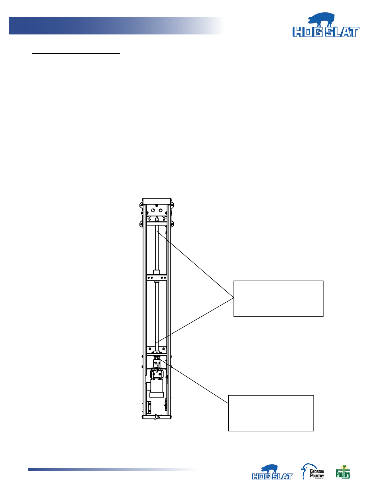
Apply grease along length of
Grease fitting for thrust
MAINTENANCE AND REPAIR
Always turn off machine and lock-out power before beginning any maintenance or repair.
Inspect machine monthly and all other external components such as cable, pulleys, clamps etc..
Inspect and clean drive screw for any foreign debris lodged in the threads. Lubricate drive screw monthly
using Lithium NLGI GRADE 2 grease along length of screw (Figure 22)
Inspect and lubricate thrust bearing every three (3) months with Lithium NLGI GRADE 2 grease.
Inspect lock collars, upper flange bearing and motor/drive screw jaw coupling set screws to ensure they
are tight.
Using local “manual” controls, run machine in both directions to ensure limit switch function and cabling
operation.
Figure 22
Hog Slat Inc. Newton Grove, NC USA September 2014
19
ACME Drive Screw – Grease
Monthly
bearing – Grease Every 3
Months
Page 20

Ventilation Systems
Notes
Hog Slat Inc. Newton Grove, NC USA September 2014
20
Page 21

Ventilation Systems
Page Intentional Left Blank
Hog Slat Inc. Newton Grove, NC USA September 2014
21
Page 22

Ventilation Systems
Page Intentional Left Blank
Hog Slat Inc. Newton Grove, NC USA September 2014
22
Page 23

Ventilation Systems
Hog Slat Limited Warranty
Hog Slat warrants products to be free from defects in material or workmanship for a period of twenty-four (24)
months from the date of original purchase. Hog Slat will credit, repair, or replace, at its option any product
deemed defective within this time period. Labor costs associated with the replacement or repair of the product
are not covered by the Seller/Manufacturer.
Conditions and Limitations
1. The product must be installed by and operated in accordance with the instructions published by the
Seller/Manufacturer or Warranty will be void.
2. Warranty is void if all components are not original equipment supplied by the Seller/Manufacturer.
3. This product must be purchased from and installed by an authorized retailer/distributor or certified
representative thereof or the Warranty will be void.
4. Malfunctions or failure resulting from misuse, abuse, negligence, alteration, accident, or lack of proper
maintenance shall not be considered defects under the Warranty.
5. This Warranty applies only to components/systems for the care of poultry and livestock. Other applications
in industry or commerce are not covered by this Warranty.
6. This Warranty applies only to the Original Purchaser of the product.
The Seller/Manufacturer shall not be liable for any Consequential or Special Damage which any purchaser may
suffer or claim to suffer as a result of any defect in the product. “Consequential” or “Special Damages” as used
herein include, but are not limited to, lost or damaged products or goods, costs of transportation, lost sales, lost
orders, lost income, increased overhead, labor and incidental costs and operational inefficiencies.
THIS WARRANTY CONSTITUTES THE SELLER/MANUFACTURER’S ENTIRE AND SOLE WARRANTY AND THIS
MANUFACTURER EXPRESSLY DISCLAIMS ANY AND ALL OTHER WARRANTIES, INCLUDING, BUT NOT LIMITED TO,
EXPRESS AND IMPLIED WARRANTIES AS TO MERCHANTABILITY, FITNESS FOR PARTICULAR PURPOSES SOLD AND
DESCRIPTION OR QUALITY OF THE PRODUCT FURNISHED HEREUNDER.
Hog Slat Retailers/Distributors are not authorized to modify or extend the terms and conditions of this
Warranty in any manner or to offer or grant any other warranties for GrowerSelect products in addition to
those terms expressly stated above. An officer of Hog Slat must authorize any exceptions to this Warranty in
writing. The Seller/Manufacturer reserves the right to change models and specifications at any time without
notice or obligation to improve previous models.
Hog Slat Inc. Newton Grove, NC USA September 2014
23
Page 24
Ventilation Systems
Part Number: HSMANUAL-024 Rev A6
This equipment must be installed in accordance with all State
and Local Codes and applica ble Regul a t ions which should
be followed in all cases. Authorities having jurisdiction
should be consulted before inst al lations are made.
Hog Slat, Inc.
PO Box 300
Newton Grove, NC 28366
Phone: (910) 594-0219
Fax: (910) 594-1392
www.hogslat.com
Copyright © 2014 by Hog Slat, Inc
HSART-215
Market: Hog
Hog Slat Inc. Newton Grove, NC USA September 2014
24
 Loading...