

Page 1
Instruction manual
GROW
BASE EC
PRO
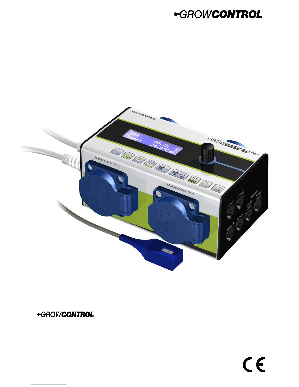
Multifunctional digital climate and CO₂ controller
with timer functions
Schlosserstr. 25
60322 Frankfurt – Germany
Mail: [email protected]
Web: www.growcontrol.de
Page 2

Instruction manual
GROW
BASE EC
PRO
2
Dear customer,
Thank you for choosing one of our products. Our name stands for innovative and reliable
products that always guarantee the best conditions for your plants. We know how closely the
environmental conditions in which you grow your plants are associated with the end result.
We hope that you enjoy using this product!
• Please read these instructions carefully and observe the relevant information.
• Store this instruction manual and make it accessible to all users.
• Ensure that you include this instruction manual when handing over the device to third
parties.
With kind regards,
GrowControl
Inhalt
1 Safety instructions ....................................................................................................................................... 3
2 Specified normal operation ...................................................................................................................... 5
3 Device description ....................................................................................................................................... 6
4 Initial use......................................................................................................................................................... 8
5 Operation ....................................................................................................................................................... 9
6 Menu overview ...........................................................................................................................................10
7 The menu and its features in detail .....................................................................................................11
8 Appendix for chapter 6 ............................................................................................................................21
9 Description of the interval timer ...........................................................................................................22
10 What to do if there are problems? .......................................................................................................23
11 Technical data .............................................................................................................................................24
12 Disposal .........................................................................................................................................................24
13 Service ...........................................................................................................................................................24
14 Warranty .......................................................................................................................................................25
Page 3
Instruction manual
GROW
BASE EC
PRO
3
1 Safety instructions
Please observe the following information besides the safety instructions of this manual. As with
all electrical devices, use this digital environmental controller carefully and cautiously to avoid
hazards due to electric shock.
Electric shock
Warning!
• Please note that the integrated power sockets of the device are enabled once the
device is connected to an electrical supply.
• Only operate the device at the voltage indicated on the device.
• Do not connect defective equipment to the device.
• Protect yourself from electric shock by avoiding body contact with earthed or grounded
surfaces such as pipes or radiators.
• Check all device parts including the power cable and extension cables as well as plug
connections for their proper condition prior to each use. Check the proper status of all
parts connected to the device. Do not use the device if it is damaged.
• Do not pull on the cables to disconnect the plug from the power socket. Hold the
device plug sockets with one hand while removing electrical equipment by pulling the
plug.
• Do not use the device if it has sustained a fall or if water has penetrated the device
interior.
• Do not use the unit during a thunderstorm.
• In the event of defects or operational faults, switch off the device immediately and
disconnect it from the power socket.
• Never hold or carry the device by the power or sensor cable.
• Maintain a distance between all device parts and warm surfaces.
• Only use the unit in dry and heated rooms.
• Never reach for a device that has been submerged in water. In such cases, pull the plug
out of the power socket immediately.
• Do not subject the device to any impact or drop the device.
Page 4
Instruction manual
GROW
BASE EC
PRO
4
Repairs
Warning!
• Do not open the device.
• Only specialist personnel may perform repairs on electrical devices. Improper repairs
may subject users to considerable danger. For repairs, please contact our customer
service or an authorized customer service point.
• If the device or parts of it are damaged, it must be repaired by the manufacturer or an
authorized customer service point.
Risk of fire
Warning!
• There is a risk of fire if the device is used improperly or these instructions for use are
ignored!
• Never use the device near highly flammable substances.
Operation
Warning!
• The device is only intended for the purpose described in these instructions. The
manufacturer is not liable for damage resulting from improper or careless use.
• Do not connect any technical equipment that exceeds the maximum output indicated
on the device or according to this instruction manual.
• Specifications concerning maximum power output are meant to be nominal power
output (no “dimmed power” at controlled outputs).
• Do not place any objects on the device.
• Do not expose the device to high temperatures.
Page 5

Instruction manual
GROW
BASE EC
PRO
5
2 Specified normal operation
This digital environmental controller is designed for speed controlling of fans and switching a
number of other devices. Depending on the mode of operation, the controller’s power sockets
may be used for connecting devices below:
• Power sockets labeled “Multifunctional Out 1-3”:
o Regular duct fans with running capacitor*
o Humidifier/dehumidifier
o Lights
o Water pumps
o Circulation fans
o CO₂ valves/generators (230V)
o Heating mats
• Power sockets labeled “Multifunctional Out 4“:
o Humidifier/dehumidifier
o Lights
o Water pumps
o Circulation fans
o CO₂ valves/generators (230V)
o Heating mats
o Electric heaters
• RJ45 jacks labeled “In/Out”:
o CO₂ sensor
o Negative pressure sensor
o Temperature sensor for heating matt
o Output extender
• RJ45 jacks labeled “EC Fans”:
o Voltage controlled EC fans
The device is not suitable for controlling any other equipment.
Always ensure that the maximum output power of the individual outputs is not exceeded.
Please find further information on the device’s label or section
11 (page 24, Table 4) of this
manual.
Warning!
If the “intake” mode is selected for the “Multifunctional Out 1” output, only standard fans
may be connected. Other devices may be damaged in the “intake” mode. When shipped,
the functions of “Multifunctional Out 1 and 2” are set to “intake” and “exhaust”.
To meet the European EMC directive, the technique used to control the regular duct fans may be
used up to a maximum 600W. Do not connect devices with a power above 600W in “intake” or
“exhaust” mode.
Avoid exposing the temperature and humidity sensor to humility above 95% RH as the
sensor may become damaged.
*When driving S&P® fans of the “TD-Silent” series, problems may occur. Do not connect fans
with an integrated rpm control.
Page 6

Instruction manual
GROW
BASE EC
PRO
6
3 Device description
The digital climate controller GROW
BASE EC
PRO
• is the control center for the ambitious indoor gardener. A number of different devices
and sensors can be connected, which guarantees maximum flexibility. In addition, the
number of power outputs can be extended with an extra device.
• is similarly able to control standard duct fans as well as EC fans, offering maximum
flexibility.
• keeps grow room temperature at the desired value by varying the air flow of the fans.
• keeps the humidity in the grow room at the designed value by switching a humidifier or
dehumidifier.
• can additionally reduce the humidity in the grow room by increasing the air flow.
• is able to control the CO₂ level in the grow room with a CO₂ sensor connected or
without a CO₂ sensor.
• is designed for the connection of the following devices: EC fans (intake, exhaust),
standard duct fans (intake, exhaust), lights, humidifiers, dehumidifiers, water pumps,
circulation fans, heating mats, electric heaters as well as CO₂ valves or generators, CO₂
sensors, negative pressure sensors, additional temperature sensors for a water tank or a
heating mat and an output extension.
The last measured temperature and humidity values are used to calculate the expected
values in the future. This enables the controller to quickly react to changes and achieve
the desired value.
• is able to regulate the temperature and humidity as precisely as ±0.5°C/±1% RH.*
• ensures a constant negative pressure in the grow room, avoiding the escape of odors
from the grow room. To maintain an accurate negative pressure, a pressure sensor can
also be connected.
• supports the option to adjust the length of a day cycle, providing equal yield with less
time required.
• can control the temperature of a heating mat. The temperature can be set to a certain
value or a temperature relative to the room temperature.
• is equipped with an easy-to-use multilingual (English, German) menu. Many different
setups can be achieved, e.g. adjusting the minimum and maximum fan speed
separately for day and night. It offers a range of information including the current
temperature, CO₂ concentration, current humidity, min/max temperature values and
humidity, current fan speeds and other information regarding the operating condition.
• saves the settings permanently to ensure that they remain available after a power
breakdown or after the controller has been temporarily out of use.
*Provided that the sizing of the connected utilities is appropriate and the fresh air temperature is
sufficiently low. The tolerance is related to the repeat accuracy rather than the absolute accuracy.
The absolute accuracy is ±3%.
Page 7
Instruction manual
GROW
BASE EC
PRO
7
Instruction manual
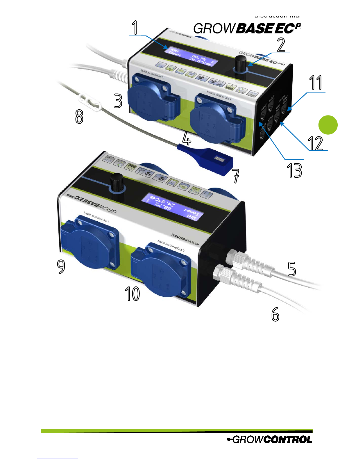
1 Display
2 Rotary switch
3 Programmable power socket (Multifunctional Out 3, 1200W)
4 Programmable power socket (Multifunctional Out 4, 2300W )
5 Mains plug for “Multifunctional Out 4“
6 Mains plug for supplying the controller and the other power outputs
7 Digital sensor for humidity and temperature
8 Hanger for the sensor
9 Programmable power socket (Multifunctional Out 1, 1200W)
10 Programmable power socket (Multifunctional Out 2, 1200W)
11 RJ45 jack for exhaust EC fan
12 RJ45 jack for intake EC fan
13 4xRJ45 jack for Humidity/Temperature sensor, CO₂ sensor, negative pressure sensor,
temperature sensor for a heating mat, output extension
1
4
5
9
10
2
6
7
8
3
13
12
11
Page 8
Instruction manual
GROW
BASE EC
PRO
8
4 Initial use
Warning!
If the “intake” or “exhaust” mode is selected for an “Multifunctional Out 1-3“output, only
standard duct fans may be connected. Other devices may be damaged in the “intake” or
“exhaust” modes. When shipped, the functions of “Multifunctional Out 1 and 2” are set to
“intake” and “exhaust”.
1. Place the humidity and temperature sensor (7) in an appropriate position inside the grow
room, usually at the top ends of your plants. Please use the hanger (8) on the sensor cable.
The sensor should not be directly exposed to the fog stream of the humidifier. Connect the
humidity and temperature sensor to any of the RJ45 jacks labeled “In/Out 1” to “In/Out 4”
(13).
2. Connect the mains plugs (5), (6) to the power supply (regular power socket). The device
has two mains plugs, offering the option to share the load (current) to two different
circuits.
3. Set the function of the “Multifunctional Out 1-4” outputs and set up all other functions
according to your requirements.
4. If using regular duct fans, we recommend disconnecting the mains plug (6) first.
Subsequently, connect the fans to the corresponding power outlets on the controller and
then reconnect the mains plug.
5. Connect appropriate devices to the other power outputs.
6. Connect the EC fans to the RJ45 jacks labeled “intake” and “exhaust” (12), (11) using a
suitable cable.
7. Connect other accessories (sensors, output extender) to the RJ45 jacks labeled In/Out 1-4
(13).
Always ensure that the maximum output power of the individual outputs is not exceeded.
Please find further information on the device’s label or section
11 (page 24, Table 4) of this
manual.
Avoid exposing the temperature and humidity sensor to humility above 95% RH as the
sensor may become damaged.
EC fans have their own power supply cable, which should be plugged to a regular power
socket (always on). It should not be connected to a power socket on the climate controller.
The fan’s rpm control and turn off is made via the signal cable from the RJ45 jack on the
controller to the EC fan.
Page 9

Instruction manual
GROW
BASE EC
PRO
9
5 Operation
The controller is operated via a menu, which is divided into two levels. It is controlled by turning
or pressing the rotary switch (2).
• On Level 1 “Info”, different information is displayed.
• On Level 2 “Setup”, all settings – except CO₂ settings – can be configured.
• On Level 3 CO₂ “Setup”, all settings for the CO₂ functions can be configured.
In the right area of the display, currently available menu options are displayed by these symbols:
F Enter (Press)
BC Go to next menu page (rotate)
k Change value (rotate)
i Info screen
Page 10
Instruction manual
GROW
BASE EC
PRO
10
6 Menu overview
RH = relative Luftfeuchtigkeit in % (relative humidity) T = Temperatur in °C
1. Ebene
„Info“
3. Ebene
„CO2-Setup“
CO₂ mode
3 . 1
Temperature
CO₂
3 . 2
Exhaust MAX
CO₂
3 . 3
Intake MAX
CO₂
3 . 6
CO
₂
concentration
3 . 9
Room volume
3 . 7
CO₂ flow
3 . 8
Exhaust MIN
CO₂
3 . 4
Fan speed
intake
1 . 9
Reset
Min/Max
1 . 7
Home-Screen
1 . 1
RH MIN/MAX
1 . 5
T MIN/MAX
1 . 6
CO₂-
concentration
1 . 2
Start
Air
exchange
3 . 1 1
2. Ebene
„Setup“
Desired
humidity (RH)
2 . 1
Desired Temperature(T)
2 . 2
Exhaust MIN
day
2 . 6
Exhaust MAX
day
2 . 5
Intake MAX
day
2 . 7
Neg. pressure
in %
2 . 1 4
Dehumidification
mode
2 . 1 8
Display
timeout
2 . 3 1
Function Multif.
Out
2 . 1 9
Pressure sensor
calibration
2 . 1 6
Clock
2 . 2 0
Interval day
ON
2 . 2 4
Time lights
OFF
2 . 2 3
Interval day
OFF
2 . 2 5
Interval night
ON
2 . 2 6
Interval night
OFF
2 . 2 7
Set language
2 . 3 0
Time lights
ON
2 . 2 2
Temperature(T)
Heater
2 . 3
Exhaust MIN
night
2 . 1 0
Exhaust MAX
night
2 . 9
Intake MAX
night
2 . 1 1
Auto calibration
pressure
2 . 1 7
Deviation
reduced rpm
2 . 1 3
Cancel & return
home
2 . 3 3
Return to
„Setup“
3 . 1 2
Negative
pressure Pa
1 . 3
Temperature
heating mat
1 . 4
Reset CO₂
warning
1 . 8
Clock
mode
1 . 1 3
Interval Info
1 . 1 2
Functionens of
outputs
1 . 1 1
Fan speed
exhaust
1 . 1 0
Temperature
unit°C/°F
2 . 2 9
Length of day
2 . 2 1
Temperature(T)
heating mat
2 . 4
Intake turnoff
day
2 . 8
Intake turnoff
night
2 . 1 2
Neg. pressure
in Pa
2 . 1 5
Go to CO₂
setup
2 . 2 8
Save&return
home
2 . 3 2
Intake MAX
CO₂
3 . 5
Enter
„Setup“
1 . 1 4
CO₂ absorbtion
time
3 . 1 0
Page 11
Instruction manual
GROW
BASE EC
PRO
11
7 The menu and its features in detail
1. Level “Info”
1.1 Home screen
This screen is the home screen. It shows the
current temperature (Temp) and relative
humidity (RH).
1.2 CO
2
concentration
This display shows the current CO₂
concentration detected by the CO₂ sensor
(available as an accessory).
ppm = parts per million
1.3 Negative pressure
This display shows the current negative
pressure (vacuum) detected by the pressure
sensor (available as an accessory).
Pa = Pascal
1.4 Heating mat
This display shows the current temperature
detected by the additional temperature
sensor. This function is designed for
controlling a heating mat. It also can be
used for controlling the temperature of a
water tank (this temperature sensor is
achievable as an accessory).
1.5 RH MIN/MAX
This display shows the minimum and
maximum humidity values (RH) that have
occurred since the last reset or start-up.
1.6 T MIN/MAX
This display indicates the minimum and
maximum temperature values (temp),
that have occurred since the last reset or
start-up.
1.7 Reset MIN/MAX
To reset the saved minimum and
maximum values, press the rotary switch
while this display is shown. After resetting,
the home screen will be displayed.
1.8 CO
2
warning
If the desired CO₂ concentration cannot be
achieved within 10 minutes in the “sensor
controlled” CO₂ mode, this suggests that
there is a problem with the CO₂ supply,
such as an empty CO₂ bottle.
The higher temperature in CO₂ mode can
be harmful for your plants without a
sufficient CO₂ concentration. Therefore, the
controller will switch to the regular “day
mode” without CO₂ dispensing and the
warning “check CO2 supply” will be
Press to reset F
CO2 warning BC
Press for F
reset MIN/MAX BC
T MINC 24.6AC i
T MAXC 26.3ACBC
RH MINC 58.4A i
RH MAXC 61.8A BC
T heating matC i
28.8AC BC
Neg. pressureC i
7pa BC
CO2 concentr.C i
1589ppm BC
RHC 60.7A i
TempC 24.8ACBC
Page 12
Instruction manual
GROW
BASE EC
PRO
12
displayed.
To delete the warning and return to
operation in CO₂ mode, press the button
while this screen is displayed.
1.1 Current fan speed intake
This screen shows the current rpm/power of
the intake fan. The “percent value”
represents the power transmitted to the fan.
The “rpm value” indicates the fan’s actual
rpm. The rpm is detected from EC fans only.
If the percent value alternates between a
number (e.g. 15%) and “off”, it means that a
connected EC fan is driven on 15% and a
standard duct fan is turned off. Please find
further details in sections “2.8 Intake fan
turnoff day” and “2.12 Intake fan turnoff
night”.
rpm = revolutions per minute
1.2 Current fan speed exhaust
This screen shows the current rpm/power of
the exhaust fan. The “percent value”
represents the power that is transmitted to
the fan.
1.3 Functions of outputs
This displays shows the chosen output
functions of the sockets “Multifunctional
Out 1-4” (Out1-Out4). If an output extender
is connected, additional outputs are
displayed according to the number of
outputs.
1.9 Interval info
This display shows the remaining time for
switching an output for which the function
“interval” is selected to switch-on or
switch-off.
1.10 Info Clock/Mode
This display shows the current time and
whether the current mode is on “day” or
“night”. This is determined by the time set
for “lights on” and “lights off” for the clock
timer.
(See also menu “Setup” “2.22/2.23 Lights
ON/OFF”) ON=Begin of day, OFF=Begin of
night.
While the CO₂ control is active, “CO2” is
displayed. The CO₂ function only operates
during “daytime”.
1.11 Enter “setup”
To enter menu level 2 “setup”, press the
rotary switch while this screen is displayed.
Press to F
enter menu BC
12C34C56 i
ModeC Day BC
Intervall ON i
inC 00C10C54 BC
Out1C Exhaust i
Out2C Intake BC
rpm exhaustC i
2876rpm 72ABC
rpm intakeC i
2476rpm 62ABC
Page 13
Instruction manual
GROW
BASE EC
PRO
13
2. Level “Setup”
The changing of a certain setting is
explained below with the desired humidity
value as an example:
1. In the menu, choose the display “2.1
desired humidity (RH)” (see menu
overview).
2. Press the rotary switch. Now the
symbol
k appears and the value to be
set blinks.
3. Choose the desired value by turning
the rotary switch.
4. Enter the chosen value by pressing the
rotary switch.
In order to save all of the changes made,
press the rotary switch while the screen
“2.23 save & return home” is displayed.
2.1 Desired humidity (RH)
Set the desired humidity value (RH).
2.2 Desired temperature (T)
Set the desired temperature value (T).
2.3 Temperature heater ON
Set the temperature to switch on a heater.
When this temperature is undercut, a heater
connected to “Multifunctional Out 4” will be
turned on. Maximum power: 2300W(10A).
In addition, a CO₂ generator (gas burner)
connected to any of the power outputs will
be activated when the specified
temperature is undercut.
2.4 Temperature heating mat
Set the temperature for a heating mat. You
can set a fix temperature or a temperature
relative to the ambient temperature.
“fix” means a fixed temperature
“amb +” means a temperature relative to
the ambient temperature
2.5 Exhaust fan MAX day
Set the maximum fan speed of the
exhaust fan during the “day period”. This
fan speed will never be exceeded. Please
find additional information in chapter 8.
Set exhaust F
day MAXC 100ABC
T heating mat:CF
fix 28ACBC
Set temp. F
heater 16AC BC
Desired F
TempC 25AC BC
Desired F
RHC 65A BC
Desired F
RHC 72A BC
Desired DF
RHC 72A E
Desired DF
RHC 65A E
Desired F
RHC 65A BC
Page 14
Instruction manual
GROW
BASE EC
PRO
14
2.6 Exhaust fan MIN day
Set the minimum airflow of the exhaust
fan during the “day” period. This set fan
speed will never* be undercut. Please find
additional information in chapter 8.
*during pressure, sensor calibration is in process,
all fans are turned off.
The minimum fan speed is 10%.
Additionally, “OFF” can be selected. This
means that the intake fan will be switched
off as long as the measured temperature is
below the desired temperature.
Ensure that the fan is still rotating at the set
minimum fan speed and the airflow is
sufficient for cooling the motor.
2.7 Intake fan MAX day
Set the maximum fan speed of the intake
fan during the day period. The specified
value will never be exceeded.
2.8 Intake fan turnoff day
Set the minimum fan speed of the intake
fan for a standard duct fan during the day
period. If this value is undercut in the
controller’s operation, the intake fan will be
switched off to maintain the negative
pressure inside the grow room. The
minimal possible fan speed is 10%.
Additionally, “OFF” can be selected,
whereby the fresh air fan will always be
disabled during the daytime.
This value is only relevant for standard duct
fans. EC fans always turn off at 10%.
Ensure that the fan is still rotating at the set
minimum fan speed and the airflow is
sufficient for cooling the motor.
2.9 Exhaust fan MAX night
Set the maximum fan speed of the
exhaust fan during the “night“ period. This
fan speed will never be exceeded. Please
find additional information in chapter 8.
2.10 Exhaust fan MIN night
Set the minimum airflow of the exhaust
fan during the “night” period. This set fan
speed will never* be undercut. Please find
additional information in chapter 8.
*during pressure, sensor calibration is in process,
all fans are turned off.
The minimum fan speed is 10%.
Additionally, “OFF” can be selected. This
means that the intake fan will be switched
off as long as the measured temperature is
below the desired temperature.
Ensure that the fan is still rotating at the set
minimum fan speed and the airflow is
sufficient for cooling the motor.
2.11 Intake fan MAX night
Set the maximum fan speed of the intake
fan during the night period. The specified
value will never be exceeded.
Set intake F
night MAXC 50ABC
Set exhaust F
night MINC 50ABC
Abluft F
Nacht MAXC100ABC
Set intake off F
dayC m 30ABC
Set tntake F
day MAXC 50ABC
Set exhaust F
day MINC 50ABC
Page 15
Instruction manual
GROW
BASE EC
PRO
15
2.12 Intake fan turnoff night
Set the minimum fan speed of the intake
fan for a standard duct fan during the
night period. If this value is undercut in
the controller’s operation, the intake fan
will be switched off to maintain the
negative pressure inside the grow room.
The minimal possible fan speed at 10%.
Additionally, “OFF” can be selected,
whereby the fresh air fan will always be
disabled during the daytime.
This value is only relevant for standard duct
fans. EC fans always turn off at 10%.
Ensure that the fan is still rotating at the set
minimum fan speed and the airflow is
sufficient for cooling the motor.
2.13 Deviation for reduced rpm
To avoid the fans running on full speed with
only a small exceedance of the desired
temperature, an allowed deviation can be
set.
The actual fan speed within this allowed
deviation depends on the minimum and
maximum fan speeds set on the previous
screens.
Some other manufacturers call this function
hysteresis.
2.14 Negative pressure in %
This setting has two different meanings
depending on whether a pressure sensor is
connected:
Without a pressure sensor connected:
With different fan speeds of the intake and
exhaust fans, a vacuum is maintained inside
the grow room, which avoids the escape of
odors from the grow room. With this value,
the amount of negative pressure can be set.
Furthermore, the intake and exhaust fans
can be balanced if different fans are used.
For example, if a value of 10% is set, this
means that the intake fan will always turn
10% less compared to the exhaust fan.
Please find additional information in section
8.
With a pressure sensor connected:
The setting limits the speed of the intake
fan compared to the exhaust fan. For
example, with a value of 0%, the intake fan
will at a maximum go as fast as the exhaust
fan. With this setting, having positive
pressure in case the pressure sensor is
calibrated inappropriately can be avoided.
2.15 Negative pressure in Pa
Set the desired negative pressure in Pa. This
setting is only relevant when a pressure
sensor is connected.
Pa = Pascal
One Pa is equivalent to the pressure
difference of approximately 7cm altitude in
the earth atmosphere.
Set negative F
pressureC 5PaBC
Set negative F
pressureC 10ABC
Deviation rpm F
reducedC 0.2ACBC
Set intake off F
nightC m 30ABC
Page 16
Instruction manual
GROW
BASE EC
PRO
16
2.16 Pressure sensor calibration
Press the button while this screen is shown
to calibrate the pressure sensor. During
calibration (which takes about one minute_
all fans will be turned off. Further
information can be found in the pressure
sensor’s manual.
2.17 Auto calibration
If “ON” is selected, the pressure sensor will
be automatically calibrated 10 minutes
before the “day period” starts (only when a
pressure sensor is connected).
2.18 Dehumidification mode
When the desired humidity (RH) is
exceeded, depending on the selected
mode the fan speeds can be increased. This
will extract the humidity from the grow
room, given that the humidity of the fresh
air is lower when inside the grow room.
This function is independent of whether a
humidifier or dehumidifier is connected to
one of the power outputs.
Three modes are available:
Off – The airflow will not be increased when
the desired humidity is exceeded.
Medium – When the desired humidity is
exceeded by 10% RH, the air flow will be
increased. A deviation of 1.5°C compared to
the desired temperature will be tolerated.
High - When the desired humidity is
exceeded by 5% RH, the air flow will be
increased. A deviation of 3°C compared to
the desired temperature will be tolerated.
High&heating – In addition to the
“high” mode, the connected heater will
be turned on when the desired humidity is
exceeded by 5% RH as long as the current
temperature is below the desired
temperature.
The relative humidity is physically coupled
to the temperature in the way that the RH
drops when heating.
Off – The airflow will not be increased when
the desired humidity is exceeded.
2.19 Function for “Multifunctional Out”
Choose the functions for the output labeled
“Multifunctional Out 1” to “Multifunctional
Out 4“. When an output extender is
connected, additional outputs will be
displayed.
The following functions are available:
Multifunctional Out1-3:
• Exhaust fan
• Intake fan
• Humidifier
• Dehumidifier
• Clock timer
• Interval timer
• Heating mat
• CO₂ valve
• CO₂&heating*
(Generator/gas burner (230V))
Function Out1C F
Exhaust BC
Dehumid F
modeC lowBC
Auto calibr.C F
ON BC
Cal. pressure F
sensor BC
Page 17
Instruction manual
GROW
BASE EC
PRO
17
Multifunctional Out4:
• Humidifier
• Dehumidifier
• Clock timer
• Interval timer
• Heating mat
• CO₂ valve
• CO₂&heating*
(Generator/gas burner (230V))
*With CO₂&heating selected, the controller
will use the generator for heating and
increasing the CO₂ level. When the CO₂
generator will be activated depends on the
settings.
2.20 Clock
The clock can be set on this menu screen.
Tipp: To set the clock to the split second,
choose the current time + 1 minute and
press the rotary switch (enter) when the
next minute starts.
2.21 Length of day
Set the length of a day cycle (day + night)
on this screen. In some phases of plant
breeding, it can make sense to adjust the
length of a day cycle, which provides equal
yield in less time requirement. For example,
if “23:25” is selected, it means that a day
cycle takes 23 hours and 25 minutes. The
last 35 minutes compared to a regular 24h
day is missing and the clock will directly
proceed from 23:24:59 to 00:00:00. Please
pay attention to this fact when setting up
the time of “Lights ON/OFF” and the clock
time.
2.22 Lights ON
Set the time to switch the lights on. An
output in “clock timer” mode will switch on
according to the set time.
2.23 Lights OFF
Set the time to switch the lights off. An
output in “clock timer” mode will switch off
according to the set time.
Function of interval timer:
Please find further information in section 8.
An output in “interval timer” mode will be
switched on and off according to the set
times.
2.24 Interval day ON
Set the interval time (period) to switch on
the output during daytime.
2.25 Interval day OFF
Set the interval time (period) to switch off
the output during daytime.
hjg
Day OFF F
00C15C00 BC
gih
Day ON F
00C15C30 BC
Lights OFFC F
16C00 BC
Lights ONC F
08C00 BC
Length of dayC F
24C00 BC
ClockC F
12C34 BC
Page 18
Instruction manual
GROW
BASE EC
PRO
18
2.26 Interval night ON
Set the interval time (period) to switch on
the output during night time.
2.27 Interval night OFF
Set the interval time (period) to switch off
the output during night time.
2.28 CO₂ Setup
Press the rotary switch to enter the “CO₂
Setup” menu.
2.29 Temperature unit
Choose the preferred temperature
unit (°C/°F).
2.30 Language
Choose the preferred language for the
menu (English/German).
2.31 Display timeout
H
ere you can set the display timeout. The
time set for the display timeout determines
the time to switch off the display
illumination. The home screen is displayed
2
0 seconds after this time has expired.
When “ON” is set, the display elimination
will be activated at all times. After a period
of 180 seconds, the home screen will be
displayed.
2.
32 Save & return home
Press the rotary switch when this screen is
displayed to save the changes made and
return to the home screen.
2.33 Cancel & return home
When this screen is displayed, press the
rotary switch to discard the changes made
and return to the home screen.
3. Menu level “CO₂ Setup”
To increase the CO₂ concentration, CO₂ can
be dispensed from a CO₂ bottle or by
generating CO₂ by burning gas. A suitable
CO₂ armature can be sourced from our
website or another specialized shop.
3.1 CO₂ function
The CO₂ concentration can be controlled
exactly by using a CO₂ sensor, or it can be
increased timing controlled without a
sensor. Furthermore, the CO₂ regulation can
be turned off.
If “sensor controlled” is selected, the
controller will calculate the required amount
of CO₂ to reach the desired CO₂ level based
upon the current measurement. Therefore,
CO2 functionC F
Sensor contr. BC
Cancel D F
return home BC
Save D F
return home BC
Display F
timeoutC 100sBC
LanguageC F
English BC
Temperature F
unitC AC BC
Drucken fur F
CO2-Menu BC
hjg
Night OFF F
00C45C00 BC
gih
Night ON F
00C15C00 BC
Page 19
Instruction manual
GROW
BASE EC
PRO
19
the CO₂ flow on the CO₂ armature, the
room dimension and the desired CO₂
concentration must be set in the menu. By
repeatedly dispensing CO₂ to the room air,
the CO₂ concentration will be kept at the
desired level. To compensate inaccuracy
regarding the actual CO₂ flow and the
entered room dimensions, the controller
will learn from previous CO₂ dispensing.
Thus, it will automatically rectify the
mentioned inaccuracies.
If “sensor&generator” is selected, the CO₂
regulation will operate similar to the
description above. The only difference is
that the minimum time for a CO₂ dosing is
higher given that it does not make sense to
trigger the CO₂ generator for only a second,
for example.
The exact procedure of the “time
controlled” function depends on the
following settings. The procedures principal
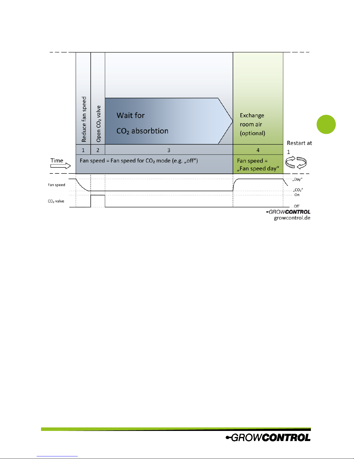
is shown in the graph on page 21.
When “OFF” is selected, the CO₂ function is
turned off.
While one of the CO₂ functions is active, the
fans will run according to the settings
below. Furthermore, the “desired
temperature CO₂” will be used.
The CO₂ dispensing will only occur during
daytime.
3.2 Desired temperature CO₂
Set the desired temperature for CO₂ mode.
When this temperature is exceeded, the fan
speeds will be increased as long the
settings following MIN/MAX settings allow..
To avoid high CO₂ wastage, it makes sense
to turn off the fans during the CO₂ mode. If
a negative pressure has to be maintained,
its also a good idea to let the exhaust fan
run on a very low speed.
3.3 Exhaust fan MAX CO₂
Set the maximum fan speed of the
exhaust fan during the “CO₂ period”. This
fan speed will never be exceeded. Please
find additional information in chapter 8.
3.4 Exhaust fan MIN CO₂
Set the minimum airflow of the exhaust
fan during the “CO₂ period”. This set fan
speed will never* be undercut. Please find
additional information in chapter 8.
*during pressure, sensor calibration is in process,
all fans are turned off.
The minimum fan speed is 10%.
Additionally, “OFF” can be selected. This
means that the intake fan will be switched
off as long as the measured temperature is
below the desired temperature.
Ensure that the fan is still rotating at the set
minimum fan speed and the airflow is
sufficient for cooling the motor.
3.5 Intake fan MAX CO₂
Set the maximum fan speed of the intake
fan during the CO₂ period. The specified
value will never be exceeded.
Set intake F
CO2 MAXC AUSBC
Set exhaust F
CO2 MINC AUSBC
Set exhaust F
CO2 MAXC 15ABC
Set desired F
tempCO2C 35ACBC
Page 20
Instruction manual
GROW
BASE EC
PRO
20
3.6 Intake MIN CO₂
Set the minimum fan speed of the intake
fan for a standard duct fan during the “CO₂
period”. If this value is undercut in the
controller’s operation, the intake fan will be
switched off to maintain the negative pressure inside the grow room. The
minimal possible fan speed is 10%.
Additionally, “OFF” can be selected,
whereby the fresh air fan will always be
disabled during daytime.
This value is only relevant for standard duct
fans. EC fans always turn off at 10%.
Ensure that the fan is still rotating at the set
minimum fan speed and the airflow is
sufficient for cooling the motor.
3.7 Room volume
Set the volume of the room to which you
wish to dispense CO₂.
Unit: (length * height * width) m*m*m = m³
3.8 CO₂ flow
Enter the flow set on the CO₂ armature or
specified for your CO₂ generator.
Unit: l/min = liter / minute
3.9 CO₂ concentration
Set the desired CO₂ concentration.
(ppm = parts per million)
The next two screens are only relevant
when the time controlled CO₂ function
without a sensor is used.
3.10 CO₂ absorption period
Set the time to wait until the plants have
absorbed the CO₂
This value is only relevant in the time
controlled CO₂ function.
3.11 Air exchange
Specify how long the fans should run in
“day mode” to exchange the room air after
a CO₂ period. If you do not want the air to
be replaced, a time of zero seconds can be
set.
This value is only relevant in the time
controlled CO₂ function.
3.12 Return to “1. Setup”
Press the rotary switch while this screen is
displayed to return to menu level “2
setup”.
Press to F
return BC
Air exchangeC F
30secBC
CO2 absorbtion F
periodC 240secBC
Concentration F
CO2C 1200ppmBC
Flow F
CO2C 10l/minBC
Room volumeC F
18ml3BC
Set intake off F
CO2C m 30ABC
Page 21
Instruction manual
GROW
BASE EC
PRO
21
This graph shows procedure of the timing controlled CO₂ function without a CO₂ sensor.
8 Appendix for chapter 6
To keep the menu descriptions clear,
additional information is provided in this
appendix:
Regarding 2.14 Negative pressure in %:
For better understanding, here two
examples are given.
Example 1: When using to equal fans for
intake and exhaust, a negative pressure of
20% means that the intake fan will generate
an air flow 20% smaller compared to the
exhaust fan.
Example 2: When operating a very small
intake fan, a negative “negative pressure”
can be chosen. This will increase the fan
speed of the intake fan compared to the
exhaust fan. When a negative pressure of
-30% is set and the exhaust fan is operating
at 60%, the intake fan will operate at 90% of
its maximum speed.
Please also pay attention to the information
below.
Regarding “Exhaust fanMAX”:
Please note that this value cannot be
smaller than the value set in “Exhaust fan
MIN”.
To always turn off the exhaust fan, “OFF”
can be selected. This is possible if “Exhaust
fan MIN” is also set to “OFF”.
Please note that his value cannot be larger
than 100% + ”negative pressure in %”. This
means that the maximum possible value
can be below 100% in case a negative
“negative pressure” is set. (e.g. -10%)
Page 22
Instruction manual
GROW
BASE EC
PRO
22
Example: for a negative pressure of -15%,
the maximum possible value would be 85%
(100% + (-15%) = 85%).
9 Description of the interval timer
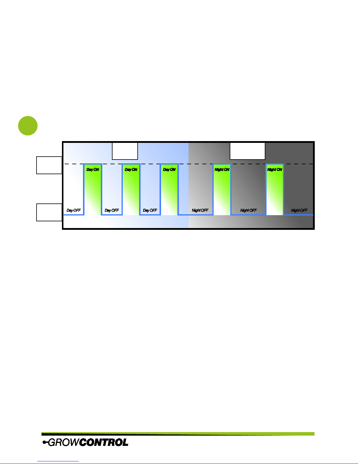
The interval timer is a recycling timer that can be used to switch devices like water pumps or
circulation fans on and off according to the times set in the menu. The time for each period
(ON/OFF) can be chosen to the split second and separately for day and night (0 seconds – 168
hours). When it switches according to the settings for day or night is determined by the clock
timer (“Lights ON”/”Lights OFF”).
This diagram shows the method of operation of the interval timer.
Day
Night
On
Off
Day
Night
On
Off
Page 23
Instruction manual
GROW
BASE EC
PRO
23
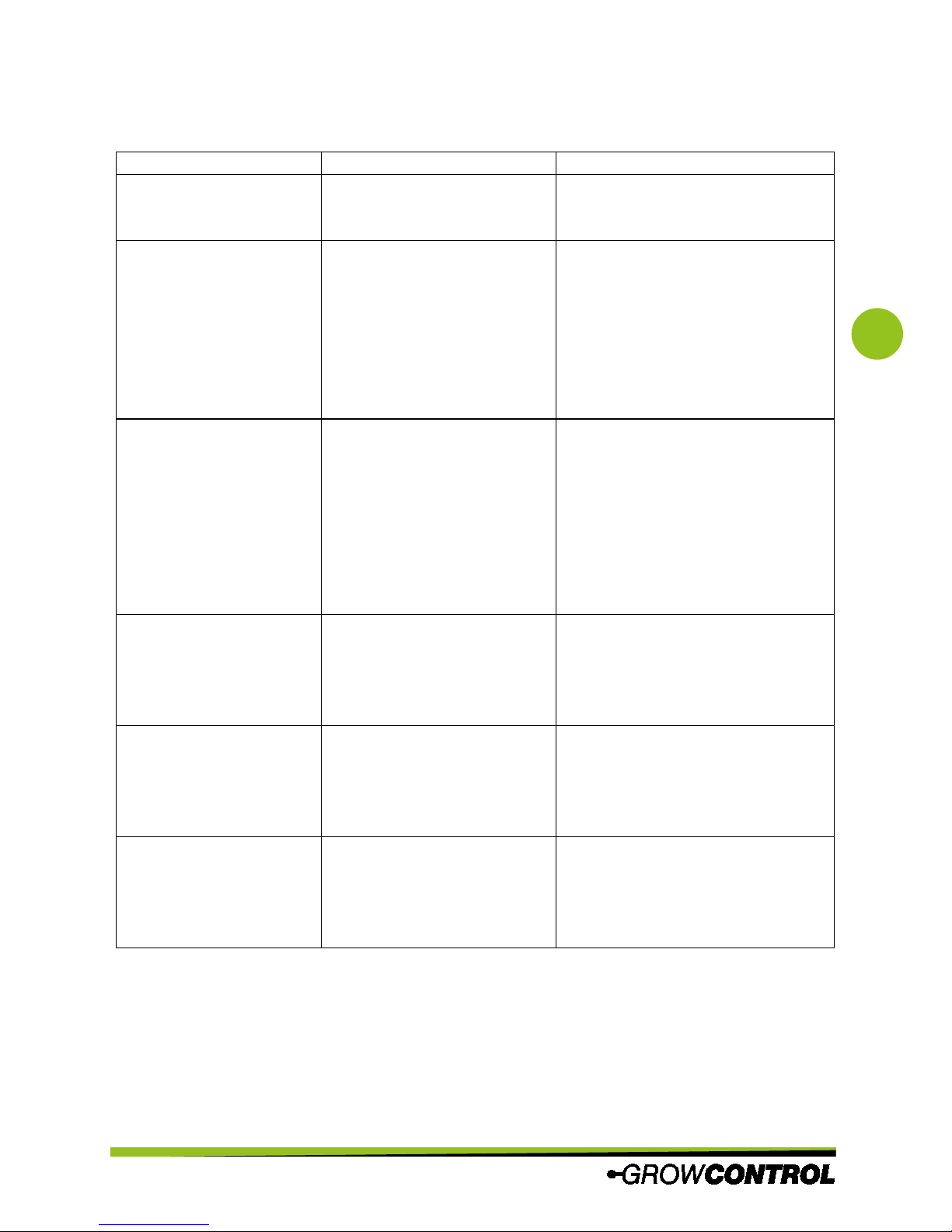
10 What to do if there are problems?
Problem Reason Advise/ Workaround
No display The mains plug is not
connected to a power
socket.
Connect the mains plug to a
power socket.
The maximum exhaust
fan speed “Exhaust fan
MAX”
cannot be
changed or the value
rang is limited.
This value cannot be smaller
than the “Exhaust fan MIN”
setting. Additionally, this
value cannot be smaller than
100% + negative pressure.
Please observe the instruction on
pages 13, 14 or 19 regarding the
“Exhaust fan MAX” menu screen.
The measured humidity
values are inaccurate or
the humidity is
permanently displayed
as 99.9%.
The sensor has been
exposed to high humidity or
wetness.
The sensor should be replaced.
Alternative:
1) Keep the sensor at a
temperature of 50 to 60°C and a
humidity <10%RH for 2 hours;
2) Following the previous step,
keep the sensor at a temperature
of 20 to 30°C and a humidity
>70%RH for 5 hours.
One or more power
outlets on the controller
are not activated, even if
the display is
illuminated.
The power output was
overloaded by a faulty or
unsuitable device.
The controller must be repaired.
Please contact customer service or
an authorized customer service
point.
The display is frequently
or permanently showing
“Sensor error code X”.
The sensor is broken. The sensor should be replaced.
One or more regular
duct fans do not run as
expected or they only
run for a short time.
The device is disturbed by an
electronic ballast.
Ensure that a distance of a couple
of centimeters is maintained
between the cables of the ballast
and ALL other cables.
Table 3
Page 24
Instruction manual
GROW
BASE EC
PRO
24
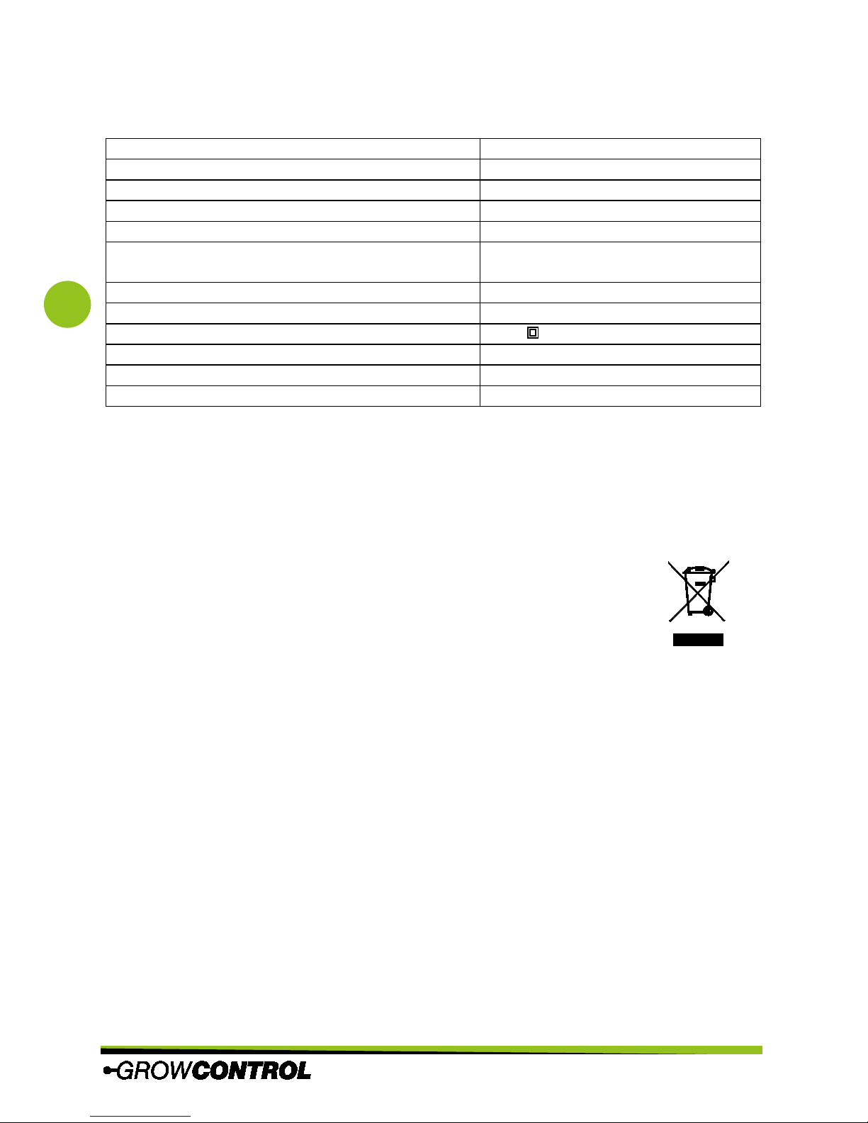
11 Technical data
Dimensions (LxWxH) 170mm x 100mm x 90mm
Length of sensor cable (T/RH) ca. 5m
Length of mains cables ca. 1.4m
Power supply 1 100-240V~ 10A 50-60Hz
Power supply 2 (for “Multifunctional Out 4“) 100-240V~ 10A 50-60Hz
Maximum power per output “Multifunctional Out 1,
2, 3“
1200W@230V 630W@120V
Maximum power “Multifunctional Out 1+2+3“ 2300W@230V 1200W@120V
Maximum power “Multifunctional Out 4“ 2300W@230V 1200W@120V
International protection marking/Protection class IP42/
Repetitive sensor accuracy T/RH ±0.1%RH/±0.2°C
Absolute sensor accuracy ±3%RH/±0.2°C
Allowed ambient temperature 10-40°C
Table 4
12 Disposal
Observe the local regulations for material disposal. Dispose of the device in accordance with EC
Directive 2002/96/EC – WEEE (Waste Electrical and Electronic Equipment). If you have any
questions, please contact the local authorities responsible for waste disposal.
13 Service
GrowControl wants to provide you the best level of service. To contact the customer service,
please send an email to [email protected].
Page 25

Instruction manual
GROW
BASE EC
PRO
25
V1.3en ©GrowControl, Excepting errors and changes
14 Warranty
This product is guaranteed against manufacturing defects for one (1) year from the original date
of purchase. GrowControl’s sole obligation in the event of such defects during this period is to
repair or replace the defective part or product with a comparable part or product at
GrowControl’s sole discretion. Except for such replacement, the sale, or other handling of this
product is without warranty, condition or other liability even though the defect or loss is caused
by negligence or other fault. Damage resulting from use, accident, or normal wear and tear is not
covered by this or any warranty. GrowControl assumes no liability for any accident, injury, death,
loss, or other claim related to or resulting from the use of this product. In no event shall
GrowControl be liable for incidental or consequential damages relating to or resulting from the
use of this product or any of its parts.
Please consider the laws and regulations of the respective country.
 Loading...