

Growatt SPH Series, SPH 4000TL3 BH, SPH 7000TL3 BH, SPH 8000TL3 BH, SPH 10000TL3 BH Operation Manual
...
Installation
Growatt New Energy
Down lo ad
Manu al
Shenzhen Growatt New Energy Technology CO.,LTD
No.28 Guangming Road, Shiyan Street, Bao’an District,
No.28 Guangming Road, Shiyan Street, Bao’an District,
Shenzhen, P.R.China
Shenzhen, P.R.China
T
+86 0755 2747 1942 +86 0755 2747 1942
service@ginverter.comservice@ginverter.com
E
www.ginverter.comwww.ginverter.com
W
GR-UM-158 A-00-GR-UM-158 A-00-
&
Operation Manual

List
1 Brief Introductio n
2 Safety
3 Product Description
1. 1 Preface
1. 2 Target G roup
1.3 Product Desc ri ption
1. 4 Safe ty I nstructions
Purpos e Us e
2. 1
2. 2 Safe ty M easure
2.3 Symb ol s in trod uction on the
SPH inve rt er
Growatt SPH seri es i nverter
3. 1
3. 2 Labe l Ex planation
3.3 Size a nd w ei ght
3. 4 The ad va ntage of the unit of
Growatt SPH
4 Unpacking
5 Installation
Basic in st al lation requirements
5.1
Instal la ti on req uire s to ols and
5. 2
RJ 45 term in al s equence of the
LAN line
5. 3 Inst al lation Instruct io ns
5.4 SPH Sy st em C onnection Mod e

6 Commissioning
6. 1
Commis si on ing of SPH
6. 2 Oper at ion modes
6. 3 Coun tr y setting
6. 4 Disp la y and button
6.5 Comm un ic ation
11 Decommissio ning
11.1 Dis ma nt ling the energy s to ra ge
11.2 Pac ki ng t he SPH inverter
11.3 Sto ri ng S PH inverter
11.4 Dis po si ng of theSPH inve rt er
7
Start-up and shut down
system
SPH
8 Attention of the installation
environment, maintenance
and cleaning
9 Fault removal
10 EU Declaration of Conformity
7. 1 Star t- up the SPH system
7. 2 Disc on nect the SPH system
12 Product specification
13 Certificate
14 Contact
Growatt SPH seri es e nergy
14.1
storag e ma ch ine product specifica ti on
14.2 DC in pu t te rminal parame te r
14.3 Torque
14.4 App en di x
1 Brief Introduction
1.1 Preface
This man ua l wi ll pro vide the users who us e th e Grow at t SPH TL3 BH Series o f Sh en zhen
Growatt New Ener gy Tec hnology Co.,LTD(Short for Growatt as bel ow ) with the detailed
product inform at ion and the install at ion instruction s. P lease re ad this manual carefull y
and put th is m an ual on some place w he re is co nv enient to install at ion, operation, o bt ain.
Any modi fi ca tions of Growatt new ener gy, we will not not if y the user.
1.2 Target Group
Growatt SPH TL3 BH i nv erter must be insta ll ed by prof essional elec tr ic al personnel who
have obt ai ne d the certifica ti on o f the re levant departme nt s. We ha ve t wo kinds of
energy s to ra ge machine for di fferent batt er y on e is for lithium ba tt er y and the other is
for lead -a ci d battery, we s ug gest: custome r sh ou ld decide which k in d of e nergy storage
machin e yo u wa nt, Growatt can provide only li th iu m battery with en er gy s torage
machin e, c us tomer can choos e le ad -acid energy st or ag e machine with no b at te ry pro vide
by Growatt while t he y can buy these batte ry f ro m ma rk et easily. Es pe cially if custome r
choose e ne rg y storage syste m wi th l ithium batter y( wh ich must be provide by Growatt)
but used f or l ea d-acid batter y or u se d lead-acid bat te ry f or lithium batt er y mo del, it will
be dange rous. In st aller can install e ne rgy storage machi ne o f Grow at t SPH TL3 BH Series
rapidl y an d trou bl eshooting, buil d co mmunication sys te m thro ug h re ad t hi s manual
carefully.If you have any quest io ns in the process of installa ti on, you can login in
www.growatt.c om a nd leave some messa ge .Or you can call our 24 -h our service
hotlin e+ 86 0 755 2747 1942.
1.3 Additional information
Growatt SPH TL3 BH S er ies is used to store energy g en er ated by the photovo lt aic cell
panels o r en er gy fro m grid if it is allowed i n th e battery, al so e ne rgy can be sent to po we r
grid through SPH T L3 B H for self consumpt io n or when Grid power is l os t, SPH TL3 BH can
be used as b ac ku p power.
SPH seri es h as s ix kinds of type:
SPH 4000 TL 3 BH
SPH 5000 TL 3 BH
SPH 6000 TL 3 BH
SPH 7000 TL 3 BH
SPH 8000 TL 3 BH
SPH 1000 0T L3 B H
Note: we d es cr ibe this series a s “S PH ” as below.
1
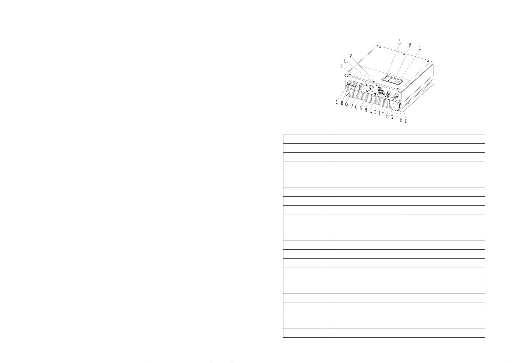
Overvi ew :
Chart 1. 1
Positi on Descri pt io n
A
B
C
D
E
F
G
H
I
J
K
L
M
N
O
P
Q
R
S
T
U
V
LED of sta tu s di splay
LCD screen
Functi on b ut ton
Ground point
EPS outp ut (o ff g ri d connection)
RSD(do n ot o pe n except by Professiona l st aff)
AC Grid (o n gr id c onnection)
Rj45 int er fa ce of DRMs(used o nl y in A ustralia)
NTC: Lea d- ac id temperature sensor t er minal
RS485 co mm un ication inter fa ce o f meter2(Rese rv ed )
RS485 co mm un ication inter fa ce o f Lithium batte ry
Rs485 co mm un ication inter fa ce o f meter1
CAN comm un ic ation interfa ce o f Li thium battery
RS232/ Wi-Fi/shi ne link cover board
Antenn a
PV switc h
PV input
Batter y te rm inal
Breathable val ve
USB inte rf ac e
DIP swit ch (s et safety stand ard)
Dry cont ac t
2
1.4 Safety Instructions
1.Plea se b e cl ear which kind of b at te ry system you wan t, l it hium battery sy st em o r lead-
acid bat te ry s ystem, if you cho os e th e wron g system, SPH can't w or k normally.
2.Plea se read th is m anual carefully before the inst al lation, The compa ny h as t he right not
to quali ty a ss urance,If not a cc ordi ng t o the instruction s of t his manual for inst al lation
and caus e eq ui pment damage.
3.All th e op er ation and conne ct io n please professional e le ctrical or mechan ic al engineer.
4.Duri ng i ns tallation, Pl ea se d on't touch the ot he r pa rts within the bo x.
5.All th e el ec trical instal la ti on must comply wi th t he l ocal electric al s af ety standards.
6.If equ ip me nts needs to main ta in , Please contac t wi th l ocal specify sy st em i nstallation
and main te na nce personnel .
7.Use th e eq ui pment to combin ed t o gr id needs to obtai n th e pe rmission of loc al p ow er
supply d ep ar tment.
8.When i ns ta ll PV modules in th e da yt ime, please tur n off th e PV switch, Othe rw is e it will
be dange rous as hi gh t erminal voltage o f mo dules in the sunshi ne .
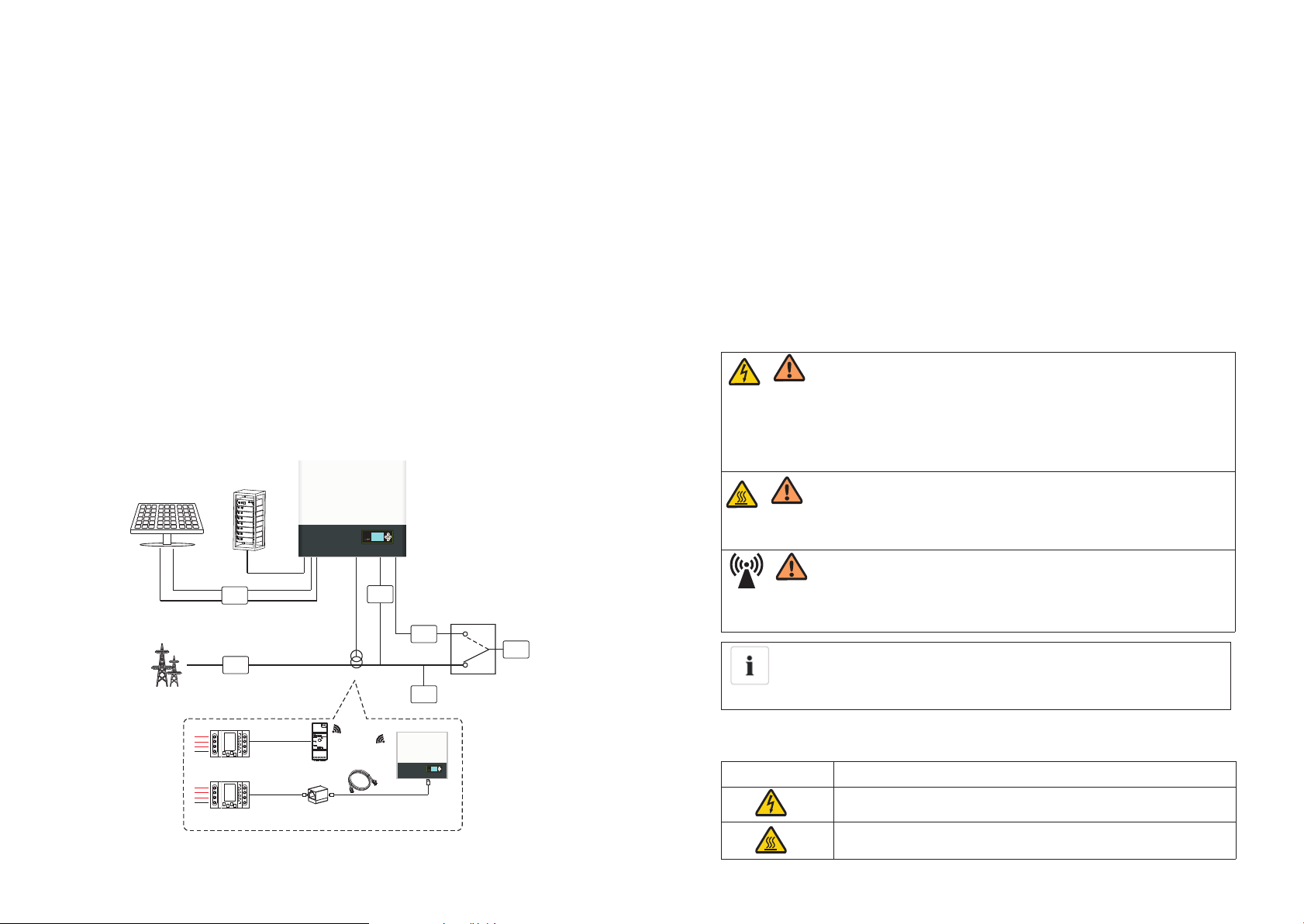
As shown a bo ve , a complete grid -c on nected system o f SP H co nsists of PV modu le s, S PH
invert er, battery, ut ility grid and othe r co mponents.
Attent io n:
As the sys te m refe r to b attery use, We must make su re venti la tion of the service
environment an d te mperature control in order to prevent the dange r of b at tery
explos io n, B attery recommended in st allation environmen t mu st b e strictly in accordanc e
with the s pe ci fication,if the s pe ci fication is IP2 0 en vi ro nm ent, the pollutio n de gree o f
the unit i s PD 2, m eanwhile the te mp er ature should be control in the 0- 40℃ o f in door
ventil at io n and the humidit y sh ou ld be 5%-85%. If th e ch os en PV modules nee ds t o
positi ve o r ne gative ground connect io n, please contact w it h Grow at t for technical
suppor t be fo re i ns tallation.
2.2 Safety Measure
2 Safety
2. 1 UsePurpose
The syst em c ha rt of SPH:
PV Arr ay
Ele ctric al Grid
1
2
L1
L2
L3
N
Elec tic met er
L1
L2
L3
N
Elec tic met er
DC
Brea ker
AC
Brea ker
Bat tery
DAN GER
Risk of hi gh v ol tage!
Releva nt o pe ration for profession al p ersonnel.
Please n ot ic e children, disabled, l ay people do not close .
Hyb rid Inv erter
Hybrid
EPSGri d
Brea ker
AC
Brea ker
Sen sor
Loa d
5m
Rail Log
5m
10m
ATS-T
Hybrid
EPS
Loa d
Superv is e an d make sure children don't play n ea r th e installatio n po si tion of energy
storag e ma ch ine.
DAN GER
Risk of bu rns on the parts sh el l of SPH inverter!
During t he w or k, Cover, she ll a ro un d, radiator is like ly t o be h ot.
CAU TION
SPH inve rt er e xists radiati on m ay be aff ect health!
Don't st ay a l on g time within 20c m ra ng e from S PH inverter.
SPH inve rt er g round connect io n
Please e ns ure SP H in verter ground connect io n is rel ia ble for make sure people's sa fe ty.
2.3 Symbols introduction on the SPH inverter
Symbol
Descri pt io n
Cautio n: R is k of electrical s ho ck !
Chart 2. 1
Cautio n : ho t su rface!
3
4
Cautio n: r is k of danger!
Danger t o li fe d ue to high voltag e in S PH .
There is residual volt ag e in S PH, SPH requires 5 minutes to
discha rg e.
Please w ai t 5 mi nutes before you open the u pp er lid or the DC lid.
Protective con du ctor terminal
Direct Current(DC)
Alternating Current(AC)
The mach in e co mplies with the requirement s of t he a pplicable
CE guide li ne s
Refer to t he o pe rating instru ct io ns.
3 Product Description
3.1 Growatt SPH series inverter
Marks of S PH
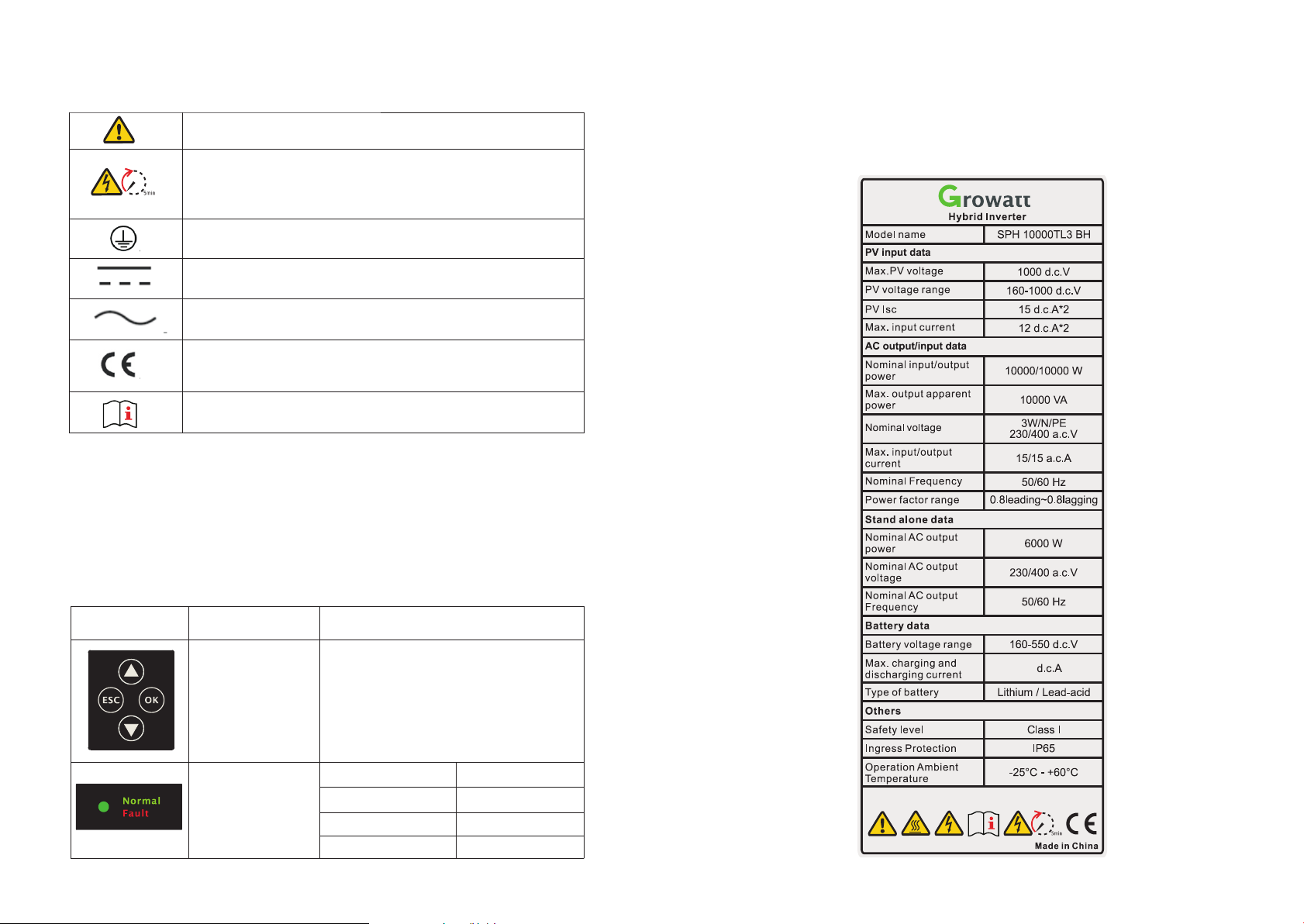
3.2 Label Explanation
Label co nt ai ns the followin g in fo rmation: for ex am pl e SPH 10000TL3 BH s ho ws a s below:
Mark
5
Descri pt io n
Push-b ut to n
Status s ym bo l of SPH
Explan at io n
Operat io n of d isplay screen and set sys te m
Green light on
Red ligh t on
Green light blin ki ng
Red ligh t bl in king
SPH run no rm al ly
fault st at e
Alarm st at e
Softwa re updat in g
21
6
Descri pt io n of label:
The type o f produc t
PV input d at a
Max. PV vo lt ag e
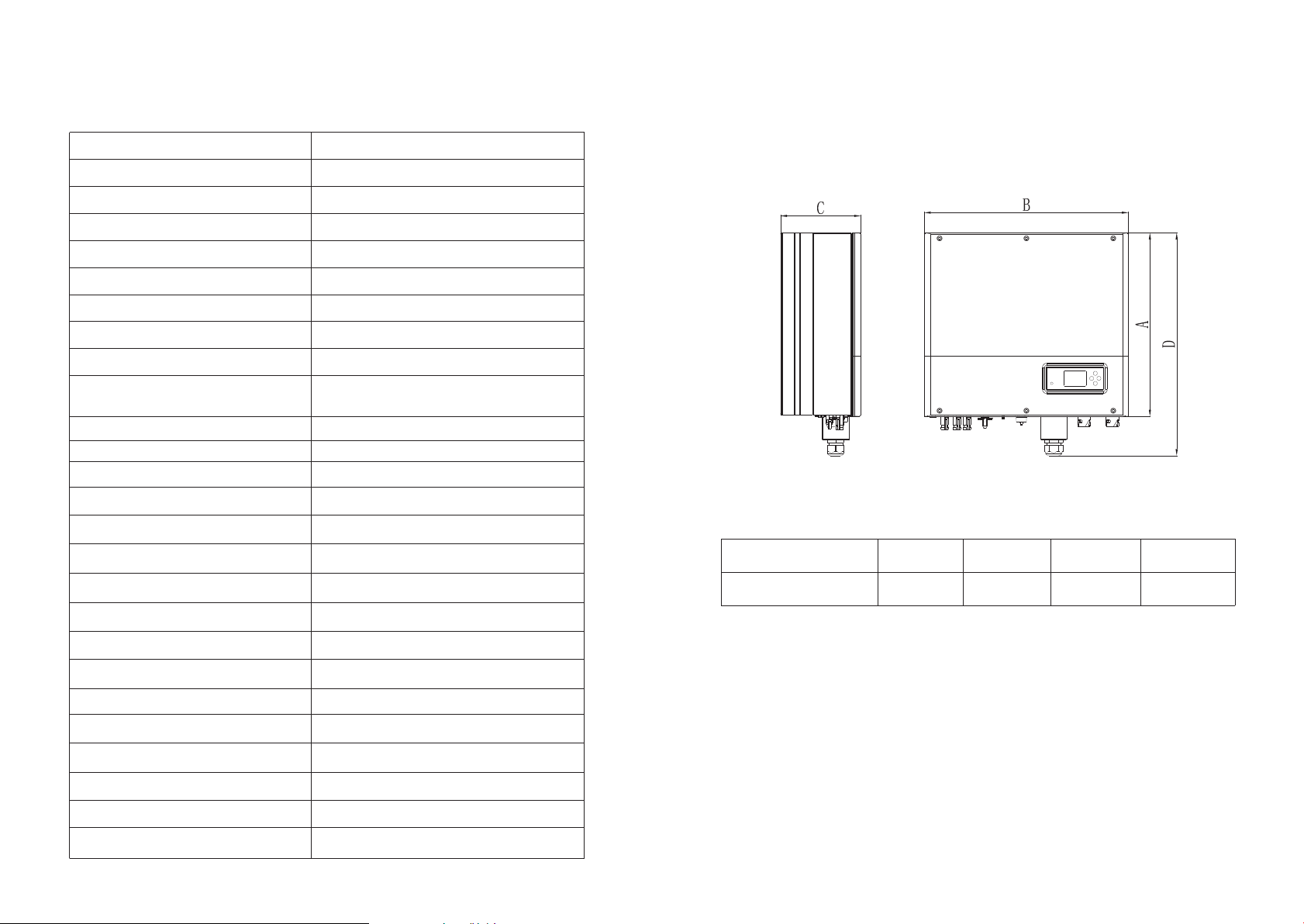
3.3 Size and weight
Growatt SPH 1000 0T L3 BH
1000Vd c
PV volta ge r an ge
PV Isc
Max. inp ut c ur re nt
AC outpu t/ in put data
Max. out pu t po wer
Max. app arent po we r
Nomina l ou tp ut voltage
Max outp ut c ur re nt
Nomina l ou tp ut Fre quency
Power fa ct or r ange
Stand al on e da ta
Nomina l AC o ut put power
Nomina l AC o ut put voltage
Nomina l AC o ut put Frequency
Batter y da ta
Batter y vo lt age range
Max. cha rg e an d discharge cur rent
Type of batt er y
Others
160~10 00 Vd c
15A*2
12A*2
10000W
10000VA
3W/N/P E
230/40 0Va c
15.2A
50Hz/6 0H z
0.8 lead in g~ 0.8 lagging
6000W
230/40 0Va c
50Hz/6 0H z
160~55 0V dc
21A
Lithiu m / Le ad -acid
Chart 3. 1
A(mm) B(mm) C(mm)
Growatt SPH TL3 BH
453 505 198 28
3.4 The advantage of the unit of Growatt SPH
weight (k g)
Safety l ev el
Ingress Protection
Operat io n Am bient Temperatu re
ClassⅠ
IP65
-25℃~+60℃
Features below :
ØAll in one d es ig n. Can improve self consu mp tion, back up and als o pi nch the valley.
ØSmart ma na ge ment, work mode c an b e se t.
ØSafe bat te ry u sed.
ØEasy ins ta ll ation.
Certif ic at es Number
7
( For Aust ra li an models)
ØTwo mp p tr ac ker input.
8
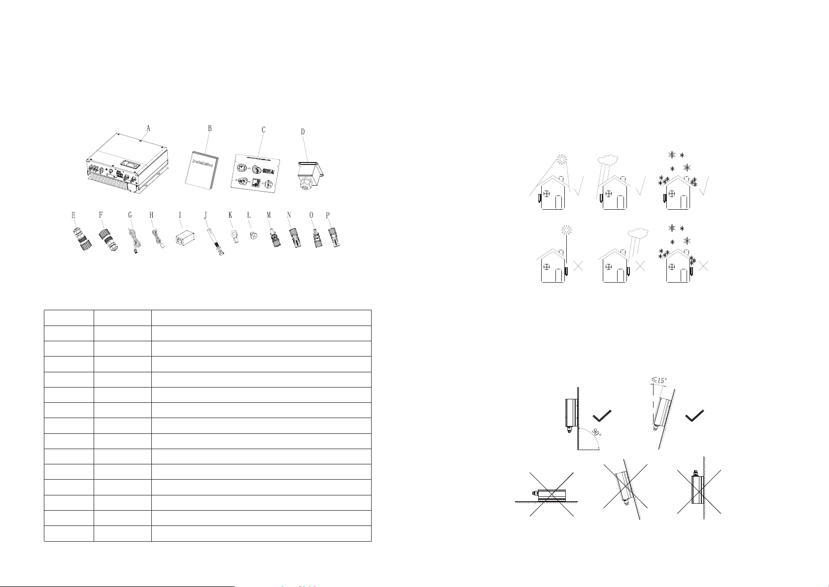
4 Unpacking and inspection
Installation 5
Before unpacking, please check whether there are any visible external dam ag es . A fter
unpack in g, pleas e c he ck wh ether there dam ag es or missi ng of the parts, if it happen,
please c on ta ct with supplie r.
Growatt SPH seri es a nd accessories sh ow s as follows:
Chart 4. 1
Item
A
B
C
D
E
F
G
H
I
J
K
L
M/N
O/P
9
Number
1
1
1
1
1
1
1
1
1
4
1
4
2/2
1/1
Descri pt io n
SPH inve rt er
User Man ua l
Paper bo ard(in st allation guide)
Wat er proo f cover
AC Grid co nn ec tor
EPS outp ut c on nector (red connector )
Commun ic at ion cable
Lead-a ci d ba ttery tempera tu re sen so r
RJ45 con ne ct or
M6 setsc rew
Ground termina l
M4 setsc rew
Mc4 conn ec to r(black conne ct or )
Mc4 conn ec to r (blue connect or )
5.1 Basic installation requirements
A. The ins ta ll ation locatio n mu st b e suitable for SP H' s we ight for a long per io d ti me.
B. The ins ta ll ation locatio n mu st c onforms with di me ns ion of SPH.
C. Do not in st al l the unit on struc tu res co ns tructed of flamma bl e or thermo labile
materi al s.
D. The Ing ress Protect io n ra te is IP65 and the po ll ut ion degree is PD2. Please refer to th e
below:
Chart 5. 1
E. Batte ry i ns tallation opt io n is n ot far away from the positi on o f SPH, the length
betwee n SP H an d battery shoul d no t be m ore th an 5m.
F. The ambient tempe ra ture s ho uld be -25℃~60℃.
G. SPH can b e in st alled in vertic al o r le an back on plane, P le as e re fe r to the below:
Chart 5. 2
10
H. Insta ll at ion position sh al l no t prev ent access to the dis co nnection means.
I. In order to ensure mach in e ca n run normally an d ea sy t o operate, plea se p ay a ttention
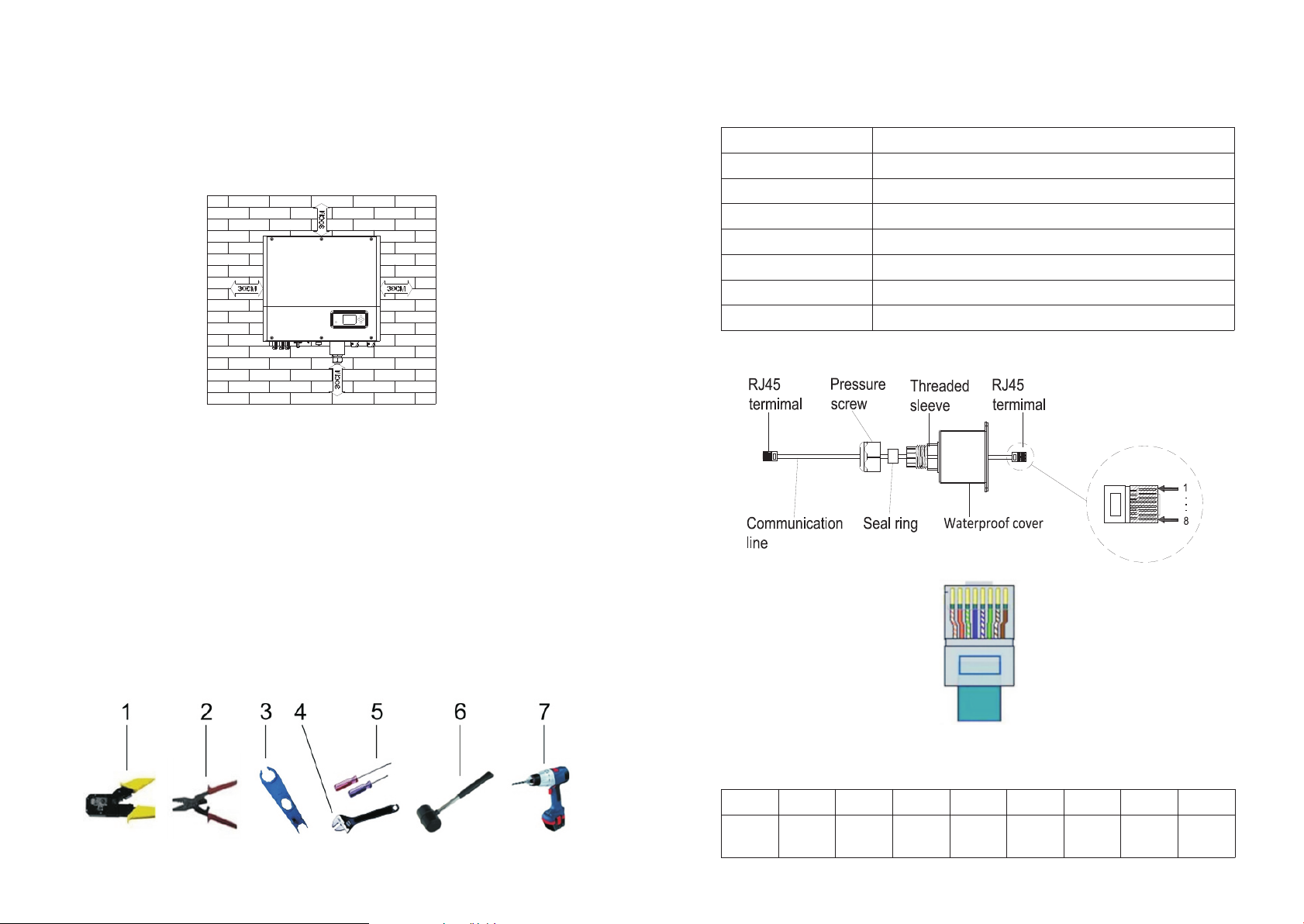
to provide adequ at e space for SPH, Plea se ref er t o be low:
Chart 5. 3
J. Do not in st al l the machine nea r te le vision antenn a or a ny o ther antennas a nd a nt enna
cables .
K. Don't i ns ta ll the machine in t he l iv ing area.
L. Be sure that the ma ch ine is out of the child ren' s reach.
M. Taking th e ba tt ery fixing spac e in to a ccount, about t he d im ensions pleas e reference
user man ua l.
N. The Inf la mm able and explos iv e da ngerous goods must not be p la ced arou nd battery in
case of ca us e se rious danger.
No.
1
2
3
4
5
6
7
LAN line R J4 5 se quence as follo w:
Descri pt io n
Press the RJ45 ter mi nal
Press battery te rm inal connector
Discon ne ct P V terminal
Unscrew nut
Unscrew screw
Knock ex pa ns ion screw
Drill ho le s on t he wall
Chart 5. 5
5.2 Installation requires tools and RJ 45 terminal sequence of the
LAN line.
When ins ta ll ing,we need to use to ol s as f ollow,prepare the follow tools be fo re
instal li ng:
Chart 5. 4
11
LAN line 1 -8 c ol ors as below:
PIN
Color
1
White
orange
2
Orange
3
White
green
Chart 5. 6
4
Blue
5
White
blue
6
green
7
White
brown
8
brown
12
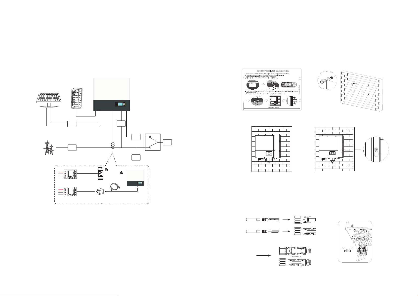
5.3 Installation Instructions
5.3.1 At te nt ion Layout(leng th o f se nsors conside r)
Growatt SPH4 00 0-10000TL3 BH o nl y use meter a s it s sensor, bef ore in stalling your
system y ou s ho uld know someth in g as b elow:
1.The ca bl e of m eter is suggest ed n ot l onger than 15m. B ec au se of this, you sho ul d
consid er t he c able length bet we en S PH and combiner b ox .
2.The me te r mu st installed in t he L l in e.
3.The in st al lation layout o f en er gy storage syst em a t ho me shows as follo wi ng :
Hyb rid Inv erter
4.Dril l fo ur Ф 8 holes at the mark p oi nt , the depth is not le ss t ha n 55mm.
5.Knoc k fo ur e xplosion bolt i nt o Ф8 h oles (As the char t 5. 8b b elow).
6.Hang t he e ne rgy storage mac hi ne o n the four setscrews (As th e ch art 5.8c below).
7.Lock t he n ut o f setscrew (As the chart 5. 8d b elow).
8.The wh ol e in stallation ha s fi ni shed.
PV Arr ay
Ele ctric al Grid
1
2
L1
L2
L3
N
Ele ctic me ter
L1
L2
L3
N
Ele ctic me ter
DC
Bre aker
AC
Bre aker
Bat tery
5m
5m
Rai lLog
Chart 5. 7
Sen sor
Hybrid
Bre aker
10m
EPSGri d
a) b)
ATS-T
AC
Bre aker
Loa d
Hybrid
EPS
Loa d
c)
d)
Chart 5. 8
5.4 SPH System Connection Mode
5.4.1 Co nn ec tion of PV termin al
PV+
5.3.2 In st al lation of SPH
1.Firs t es ti mate the size of th e in ve rter on the wall;
2.Dete rm in e the location of t he d ri ll hole through the cardboard (instal la ti on guide), put
the cardboard on the wal l an d ma ke sure the top edge of the cardboard is hori zo nt al.
3.Mark f ou r po ints at the wall vi a th e ho le of the paper boa rd, then remov e th e
cardboard.
13
PV-
The In verte rSide
Chart 5. 9
14
 Loading...