

Page 1
Installation
&
Operation Manual
No.28 Guangming Road, Shiyan Street, Bao'an District, Shenzhen,
Shenzhen,P.R.China
+ 86 755 2747 1942
service@ginverter.com
www.ginverter.com
T
E
W
GR - UM - 127 - A - 01
Installation Manual Of PV Off-grid Inverter
SHE NZHEN G ROWATT N EW ENER GY TECH NOLOG Y CO.,LT D
Page 2

Brief Introduction
1.1 Prefa ce
1.2 Targ et Gro up
1.3 Produ ct Descri ptio n
1.4 Basi c Syst em Arc hite ctur e
1.5 Produ ct Overvi ew
Safety Instructions
Installation
3.1 Unpa ckin g and In spectio n
3.2 Basi c inst alla tion requi reme nts
3.3 Inve rter c onne ction
Communication
Connection
Contents
1
2
3
4
6.1 Powe r on/o ff
6.2 Oper atio n and di splay pan el
Specifications
Trouble Shooting
Operation
Dry contact
6
5
7
8
Manufacturer Warranty
9
Appendix
10
Contact
11
Page 3
1 Brief Introduction
1.1 Preface
This man ual d escr ibes the as semb ly, ins tallati on, op era tion a nd troubl esho otin g of
Gro watt SPF Se ries of GROWATT NE W ENE RGY TE CHNOLOG Y CO.LTD. SHE NZHE N(Sh ort
for Grow att Ne w Ene rgy as belo w). P leas e read this m anual car eful ly and put this
manual o n som e plac e whe re is conve nien t to in stal lation, o pera tion, obt ain. Any
modifi cati ons of Grow att New Ene rgy, we w ill n ot notify t he us er.
Only qualifie d and tra ined elec tric al tech nic ians are allo wed to ins tall an d ope rate
Gro watt SP F300 0/50 00/SPF3 000 PLUS. SPF300 0/50 00 seri es
pro duct s are c ompa tible wit h lit hium -ion and le ad ac id ba tter y. If cho osing lit hium-io n
batter y, yo u are al lowed to us e lit hium b attery fr om Gro watt only. For lead ac id
batter y, yo u are e asy to find i t on th e mar ket. H owever, we s tron gly re comm end y ou to
contac t you r instal ler o r Gro watt cus tome r servic e hot line + 86 -075 5-27471 942/ 400931-31 22 to co nfir m before the p roce dure .
Gro watt /S PF30 00 PLUS
Gro watt SP F300 0/50 00 is sort of off- grid invert er. It use s s urplus PV
genera tion to char ge the bat tery in the day time . Afte r t he sun goe s d own, the PV
genera tion is unav aila ble, it dischar ge the battery or util ize grid elec tric ity to p ower
the load a t nigh t. It en joys foll owin g feat ures :
Pure sine w ave inver ter
Built- in MPP T sola r charge co ntroller
Config urab le in put v olta ge ra ng fo r hom e app lian ces a nd pe rsonal compu ters via LCD
settin g
Config urab le bat tery char ging c urre nt bas ed on ap plicati ons vi a LCD se tting
Config urab le AC/ Solar Cha rger p rior ity via LCD s etti ng
Auto rest art while A C is rec over ing
Overlo ad/O ver te mperatu re/Short c ircu it pro tect ion
Smart ba tter y char ger desig n for op timi zed batte ry per form ance
Cold sta rt fun ctio n
/SPF30 00 PLUS
1.3 Product Description
2
1.2 Target Group
1
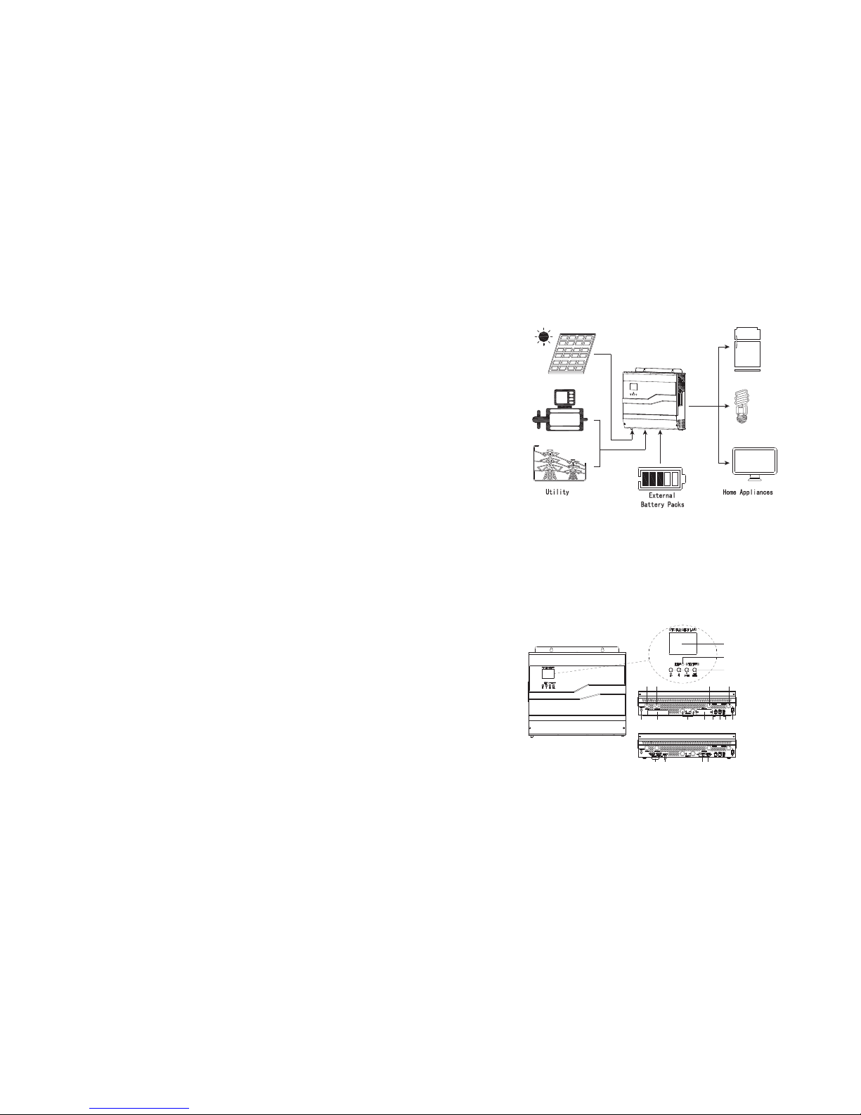
1.4 Basic System Architecture
So la r po wer
Ge ne ra tor
OR
As s hown i n abo ve system d iagram, SPF300 0/50 00 is u sed t o
power co mmon hous e applian ces in cluding s ome i nduc tive load s uch a s light,
ref rige rator. Also, die sel g ener ator and po wer g rid can be co mpensat ion in whic h sol ar
energy i s ins ufficien t as we ll as t o char ge th e battery.
Gro watt /S PF30 00 PLUS
1.5 Product Overview
DEFGHIOJ
K L N M
A
B
C
P Q SR
NOTE: Fo r par alle l model ins tall ation and oper atio n, pl ease c heck sepa rate “par alle l &
three-p hase inst allatio n guid e” fo r the d etai ls. O nly SP F5000 hav e the f unct ion .
Page 4
43
Safety Instructions 2
1. Pleas e be cle ar whi ch kind of ba tter y syst em you want , lith ium ba ttery sys tem or
led-ac id bat tery s ystem, if y ou cho ose th e wron g syst em, energ y stor age
system c an’t work no rmal ly.
2. Before u sing the un it, re ad all i nstr uctions a nd cau tion ary marki ng on th e unit ,
the batt erie s and al l appropri ate secti ons of t his ma nual. The c ompa ny has t he
right no t to qua lity a ssuranc e, if no t acco rdin g to the i nstruct ions o f this m anual
for inst alla tion a nd cause eq uipm ent da mage.
3. All the o pera tion a nd connec tion p leas e prof essi onal elec tric al or me chanica l
engine er.
4. All the e lect rica l install atio n must c omply wit h the lo cal el ectrica l safe ty
standa rds.
5. When in stal l PV mod ules in the d ayti me, in staller s houl d cove r the PV modu les by
opaque m ater ials , otherwi se it wi ll be da ngerous as h igh termi nal vo ltag e of
module s in the s unsh ine
6. CAUTI ON:To reduce r isk of i njur y, char ge onl y deep-cy cle le ad-a cid type
rec harg eable bat teri es and l ithium ba tter ies. O ther type s of bat teri es ma y burs t,
causin g pers onal i njury and d amag e.
7. Do not di sass embl e the unit. Tak e it to a qu alif ied servi ce cen ter wh en servic e or
rep air is r equi red. I ncorrect r e-as sembly ma y resu lt in a ri sk of el ectric sh ock or
fire.
8. To red uce ri sk of elect ric sh ock, d isconne ct all w irin gs before attem ptin g any
mainte nanc e or cle aning. Turn ing off the unit wi ll not r educ e this r isk.
9. NEVER c harg e a froz en bat tery.
10. For op timu m oper ation of th is inv erte r, plea se fol low re quir ed spe c to sel ect
appropr iate cabl e size . It’s ver y importa nt to co rrec tly op erate thi s inve rter.
11. Be ver y caut ious w hen worki ng wit h meta l tools on or a round batt erie s. A
otenti al ris k exis ts to drop a too l to spark or s hort c ircu it bat teries or o ther
electr ical p arts a nd could ca use an e xplo sion.
12. Plea se str ictl y follow in stal lati on pro cedu re whe n you want to d isco nnec t AC or
DC termi nals . Plea se ref er to IN STALL ATION sect ion of t his ma nual for th e deta ils.
13.GROU NDIN G INST RUCTION S -Thi s inve rter shou ld be co nnec ted to a perm anen t
gro unde d wiring sy stem . Be sur e to com ply with lo cal re quir emen ts and
reg ulat ion to inst all th is inv erter.
14. NEVE R caus e AC out put and DC in put sh ort ci rcui ted. D o NOT conne ct to th e
mains wh en DC in put sh ort circui ts.
15. Make s ure the inve rter i s comp letely as semb led, b efore the opera tion .
A
B
C
D
E
F
G
H
I
J
K
L
M
N
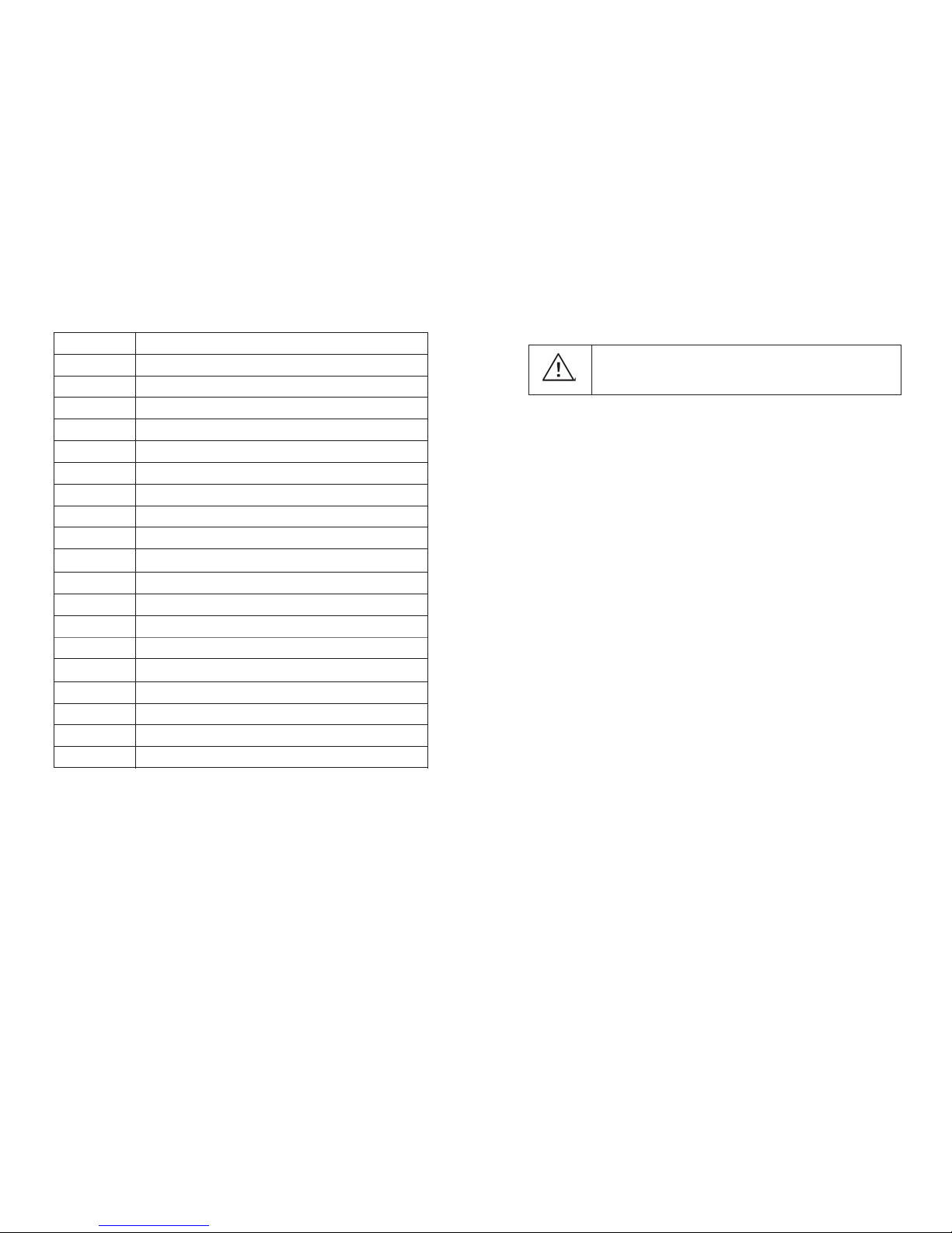
LCD disp lay
Status i ndic ator
Functi on but tons
Power on /off switc h
Dry cont act
RS485 co mmun icat ion port
BMS comm unic atio n port
WIFI baff le
Batter y inpu t
Circuit b reak er
AC input
AC outpu t
PVB inpu t
PVA input
Positi on Descri ptio n
O
P
Q
R
S
Parall el baffle( SPF 5000 /SPF300 0 PLUS h ave)
Parall el com muni cation ca ble( SPF 5000 h ave)
Parall el cur rent s hari ng cab le(SPF5 000 ha ve)
WIFI cab le
WIFI pow er
WAR NING : This c hapter co ntai ns imp ortant sa fety a nd ope rating
instru ctio ns. Re ad and keep t his ma nual f or future re fere nce.
Page 5
5
6
3 Installation
3.1 Unpacking and Inspection
3.2 Basic installation requirements
Before i nsta llat ion, plea se in spec t the u nit. Be sur e that noth ing insid e the p acka ge is
damage d. You sh ould have r ecei ved t he fol lowing it ems i nsid e of pa ckag e:
The unit ×1
User man ual× 1
Setscre ws×3
1.The ins tall ation loc atio n mus t be su itab le fo r SPF S erie s inverte r’s weight fo r a lon g
pe riod t ime .
2.The ins tall ation loc atio n mus t conform w ith d imen sion of SPF Seri es invert er.
3.Do not in sta ll the unit o n str uctu res co nstruct ed of f lamm able or the rmo l abil e
ma teri als .
4.The Ing ress P rote ction rat e is IP 20 an d the pollu tion degre e is PD 2, Th e install a rea
sh all be gene rall y con diti oned in ter m of te mperatu re, hu midi ty an d air f iltr atio n.
5.Batte ry ins tallati on opt ion i s not f ar below th e pos itio n of in vert er.
6.The hum idit y of th e ins tall atio n loc atio n sho uld be 5 ~ 85% .
7.The amb ient temp erat ure shoul d be 0℃ 55 ℃
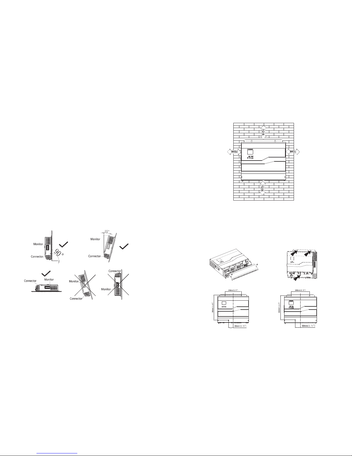
8.SPF Ser ies i nver ter can be insta lled i n ver tica l or le an ba ck on p lane , Please re fer to
th e belo w Ins tall ation pos itio n sha ll not prev ent acces s to the disc onnecti on mea ns.
~ .
Figure 3. 1
9.In orde r to en sure m achi ne ca n run n orma lly and eas y to op erat e, pl ease pay
attent ion to provide ad equate sp ace for SPF Seri es invert er. Please re fer to belo w:
Figure 3. 2
10.Do not i nst all th e mac hine near t elev ision ant enna or any othe r antenna s and
an tenn a cab les.
11.Don’t inst all the mac hine in the livi ng are a.
12.Be sur e that the ma chine is out of the chi ldre n’s reac h.
13.Inst all th e uni t by sc rewi ng thr ee cre ws as b elow. It’s rec ommende d to use M6
sc rews .
Figure 3. 3
(SPF500 0/SP F300 0 PLUS)
(SPF300 0)
Page 6
7
8
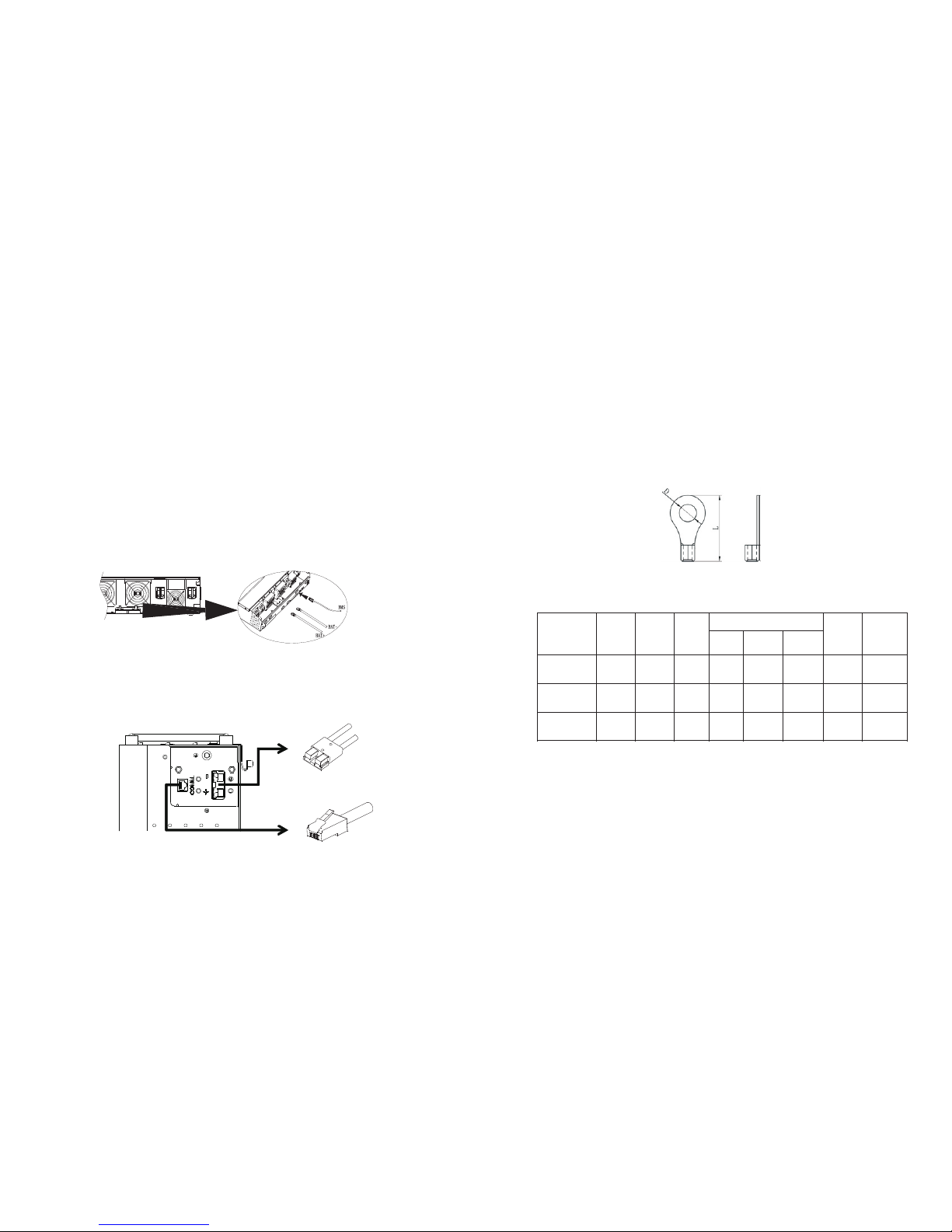
3.3 Inverter connection
3.3.1 Lithium battery connection
If c hoos ing l ithi um batter y for SPF 3000 /5000/S PF30 00 PL US, yo u are a llow ed
to u se Gro watt lith ium batte ry onl y. Ther e’re t wo co nnec tors on the lith ium batte ry,
RJ45 por t of BM S and p ower cabl e
Please f ollo w bel ow steps to impl emen t lithium b atte ry co nnec tion:
1.Assem ble ba ttery rin g ter mina l based on re commend ed bat tery cabl e and t ermi nal
si ze (sa me as L ead a cid, see s ecti on 3. 3.2 fo r det ails ) .
2.Inser t the r ing te rminal of batt ery ca ble f latl y int o batt ery c onne ctor of inv ert er and
ma ke sur e the b olts are ti ghte ned w ith to rque of 2-3 Nm.Make s ure po larity at both
th e batt ery a nd the inve rter/ch arge i s cor rect ly connec ted an d rin g termina ls are
ti ghtl y scre wed t o the b atte ry te rmin als.
3.Conne ct the end of RJ45 o f bat tery t o BMS c ommunic atio n por t of in vert er
Gro watt
4.The oth er en d of RJ45 ins ert t o batt ery c omm port.
Figure 3. 4
Note: if c hoo sing l ithium ba tter y, make sure t o connect t he BM S comm unicati on
cable be twee n the b attery an d the i nver ter. Al so, y ou need to ch oos e batt ery t ype as
“lithi um bat tery”
Figure 3. 5
3.3.2 Lead acid battery connection
User can c hoo se pro per capac ity le ad ac id batter y with a nomi nal v olta ge at 4 8V. Also,
you need t o cho ose batte ry type as “l ead a cid batte ry”.
WAR NING ! For s afety ope ration an d regu lation co mpli anc e, it’s re quested t o ins tall a
separa te DC o ver-c urre nt pro tect or or d isconne ct dev ice b etwe en ba tter y and
invert er. It ma y not b e requ ested to ha ve a di sconnec t device in some a ppli cations ,
howeve r, it ’s st ill re quested t o hav e over- current p rote ctio n ins tall ed.
WAR NING ! All w iring mus t be pe rfor med b y a qua lifi ed pe rson nel.
WAR NING ! It' s very impo rtant for s ystem saf ety a nd eff icie nt op erat ion t o use
appropr iate cabl e for b attery co nnec tion. To redu ce ri sk of i njur y, plea se use the
pro per re com mend ed cable an d ter mina l size as below.
Ring ter mina l:
Figure 3. 6
Recomm ende d battery c able and te rminal si ze:
Mod el
SPF 3000
8
SPF 5000
Table 3.1
Note: fo r lea d acid batt ery, th e reco mmen ded c harg e cur rent i s 0.2 C© bat tery
capaci ty)
Please f ollo w bel ow steps to impl emen t lead-ac id bat ter y conn ection:
1.Assem ble ba ttery rin g ter mina l based on re commend ed bat tery cabl e and t ermi nal
size.
2.Conne ct all batt ery packs a s uni ts req uire s. It’s sugges ted to conn ect at leas t
100Ah ca paci ty ba tter y for 3 KVAmo del a nd at l east 200A h capa city batt ery f or 5KVA
model.
3.Inser t the r ing te rminal of batt ery ca ble f latl y int o batt ery c onne ctor of invert er
and make s ure t he bol ts are tigh tene d wit h torq ue of 2 -3Nm.Ma ke sur e polarit y at
both the b att ery an d the i nverter /cha rge is corr ectl y con nect ed and ring term inal s
are tigh tly sc rewe d to th e bat tery t erm inal s.
Dim ensio n(mm)
Cro ss
-se ction
Inn er
dia meter
Len gth
200 AH
130 A
14
6.4
29. 2 2-3 Nm
40A
2*8 A
WG
100 AH
1*8 A
WG
SPF 3000 PL US
Rec ommen
ded c harge
cur rent
20A
Torqu e
2-3 Nm
23. 86.4
Max .
cha rging
Cur rent
Cap a
cit y
Dia me
ter
100 A
100 AH
100 A
14
6.4
29. 2 2-3 Nm
20A
1*6 A
WG
Page 7

1211
3.3.4 PV connection
CAUTIO N: Bef ore conne ctin g to PV m odules, p lease ins tall sepa rate ly a DC circu it
bre aker betw een inver ter and PV mo dules.
WAR NING ! All w iring mus t be pe rfor med b y a qua lifi ed pe rson nel.
WAR NING ! It' s very impo rtant for s ystem saf ety a nd eff icie nt op erat ion t o use
appropr iate cabl e for P V mod ule co nnectio n. To reduce ri sk of i njur y, plea se us e the
pro per re com mend ed cable si ze as b elow.
Mod el
Max c hargi ng curr ent pe r strin g
Dia meter
Torqu e
Table 3.3
PV M odul e Sel ecti on:
When sel ecti ng proper P V mod ules , please be sure t o conside r belo w par amet ers:
1.Open ci rcui t Voltage( Voc) of PV mod ule s not excee ds max. PV ar ray o pen circuit
voltag e of in vert er.
2.Open ci rcui t Voltage( Voc) of PV mod ule s shou ld be h igher tha n min . batt ery v olta ge.
Mod el
SPF 3000
Max . PV arra y open ci rcuit v olta ge
PV ar ray MPP T volta ge rang e
Min . batte ry volt age for P V charg e
Table 3.4
There’r e two p airs of str ing f or PV i nput . Also, it’s allow ed to m ake tw o PV in put
parall el (se e sec tion 6.2 fo r det ails ).
Please f ollo w bel ow steps to impl emen t PV in put conne ctio n:
1.Remov e insu lation sl eeve 10 mm f or pos itive and nega tive c onducto rs.
Figure 3. 10
2.Check c orre ct polari ty of c onne ctio n cab le fro m PV mo dule s and P V inp ut
connec tors . Then, con nect posi tive pole ( +) of c onne cti on cab le to p ositive p ole ( +)
of P V inpu t con nect or. Con nect nega tive pole ( -) of c onnecti on cab le to n egative
pole (-) o f PV in put c onne ctor.
Figure 3. 11
Figure 3. 12
3.Make su re the wires are se cure ly co nnec ted.
3.3.5 Finally assemble
After co nnec ting all wirin gs, pl ease put botto m cove r bac k by sc rewi ng two scre ws
as s hown b elo w:
Figure 3. 13
SPF 3000
35A
1*1 0AWG
1.2 -1.6N m
SPF 5000
35A
1*1 0AWG
1.2 -1.6N m
SPF 3000 PL US
35A
1*1 0AWG
1.2 -1.6N m
SPF 5000
SPF 3000 PL US
145 Vdc
60~ 115Vd c
36V dc
Page 8

Figure 3. 7
WAR NING : Shock Haz ard
Instal lati on mus t be perfor med wi th car e due to h igh ba ttery vol tage
in serie s.
CAUTIO N!! Do n ot pla ce anythi ng bet ween t he flat par t of the i nver ter
termin al and t he rin g termina l. Oth erwi se, overh eati ng may o ccur.
CAUTIO N!! Do n ot app ly anti-o xida nt sub stance on t he ter mina ls
before te rminals a re con nect ed tig htly.
CAUTIO N!! Be fore m akin g the fi nal DC conn ecti on or cl osing DC
bre aker /discon nect or, be su re pos itiv e (+) mu st be co nne cted t o
positi ve (+) a nd neg ative (-) m ust be c onne cted to neg ativ e (-).
3.3.3 AC input & output connection
CAUTIO N: Bef ore conne ctin g to AC i nput powe r sou rce, p leas e ins tall a sepa rate AC
bre aker betw een inver ter and AC in put p ower source. Th is wi ll ens ure the inv erter can
be s ecur ely di sconnec ted durin g main tenance a nd fu lly pr otec ted f rom ov er cu rren t of
AC i nput . The r ecom mend ed sp ec of A C brea ker is 32A for 3KVA and 50 A for 5 KVA.
CAUTIO N: The re are two te rminal bl ocks with “ IN” a nd “OUT” ma rkin gs. P leas e do
NOT mis- conn ect i nput and ou tput conn ecto rs.
WAR NING ! All w iring mus t be pe rfor med b y a qua lifi ed pe rson nel.
WAR NING ! It' s very impo rtant for s ystem saf ety a nd eff icie nt op erat ion t o use
appropr iate cabl e for A C inp ut con nection . To reduce ris k of in jury, p leas e use t he
pro per re com mend ed cable si ze as b elow.
Sugges ted ca ble r equi reme nt fo r AC wi res:
SPF 3000
1*1 0AWG
1.4 -1.6N m
SPF 5000
1*8 AWG
1.4 -1.6N m
Table 3.2
Please f ollo w bel ow steps to impl emen t AC in put/ outp ut co nnec tion:
1. B efor e maki ng AC i nput/ou tput c onnecti on, be sure t o ope n DC pro tector or
discon nect or first.
2. R emov e ins ulat ion sleev e 10mm for si x con duct ors. And sh orten pha se L an d
neutra l cond uctor N 3 mm .
3. I nser t AC in put wires a ccor ding t o pol arit ies i ndic ated on ter minal blo ck an d
tighte n the t ermi nal screws. Be su re to c onne ct PE p rote ctiv e con duct or ( ) first .
→Gro und (y ellow-g reen )
L→LINE (bro wn)
N Neutra l (blu e)→
Figure 3. 8
WAR NING :
Be sure tha t AC power so urce i s disc onne cted befo re att empt ing to
hardwir e it to th e unit.
4.Then, i nser t AC ou tput wire s acco rdin g to po laritie s indi cated on termi nal
blocka nd tig hten term inal scre ws. Be sure t o connect P E prot ective co nductor ( )
first.
→Gro und (y ellow-g reen )
L→LINE (bro wn)
N Neutra l (blu e)→
Figure 3. 9
5.Make su re the wires are se cure ly co nnec ted.
CAUTIO N: Be s ure to c onnect AC wires with c orre ct po lari ty. If L a nd N wi res ar e
connec ted re vers ely, it may ca use u tili ty short- circ uite d when thes e inv erte rs are
worked i n par alle l operati on.
9
10
Mod el
Wi re size
Torqu e valu e
SPF 3000 PL US
1.4 -1.6N m
1*1 0AWG
Page 9
13 14
4 Communication Connection
Gro watt
Gro watt
SPF300 0/50 00/S PF3000 PLUS i s co mpatibl e wi th WIF I commu nica tion .
There’r e two meth ods to co nfig ure a nd mo nito r the device b y loc al PC or Sm artp hon e
APP. Ab out how to u se W IFI modu lar, plea se r efer to WIFI user manual and follo wing
picture s hows how to i nsta ll WIF I for SPF300 0/50 00/S PF3000 PL US:
Figure 4. 1
5 Dry contact
There’s on e dry c onta ct (2A/30 VDC) a vailabl e on th e rear pane l. It c ould b e use d to
delive r sign al to e xternal devi ce whe n bat tery volt age re ache s war ning leve l.
Uni t
Sta tus
Con ditio n
Dry c ontac t
por t:
NC & N
NO & N
Pow er Off
No ou tput is p owere d
Clo se
Ope n
Pow er On
Out put is po wered f rom Uti lity
Clo se
Ope n
Out put is
pow ered
fro m
Bat tery
or So lar
AC ou tput
sou rce is "U TI
fir st"
Bat tery vo ltage < L ow DC
war ning v oltag e
Ope n
Clo se
Bat tery vo ltage > B atter y
cha rging r each es floa ting
sta ge
Clo se
Ope n
AC ou tput
sou rce is "P V
fir st" or "B AT
fir st”
Bat tery vo ltage < S ettin g
val ue in "Ba ttery L ow
Volt ”
Ope n
Clo se
Bat tery vo ltage > B atter y
cha rging r each es floa ting
sta ge
Clo se
Ope n
Table 5.1
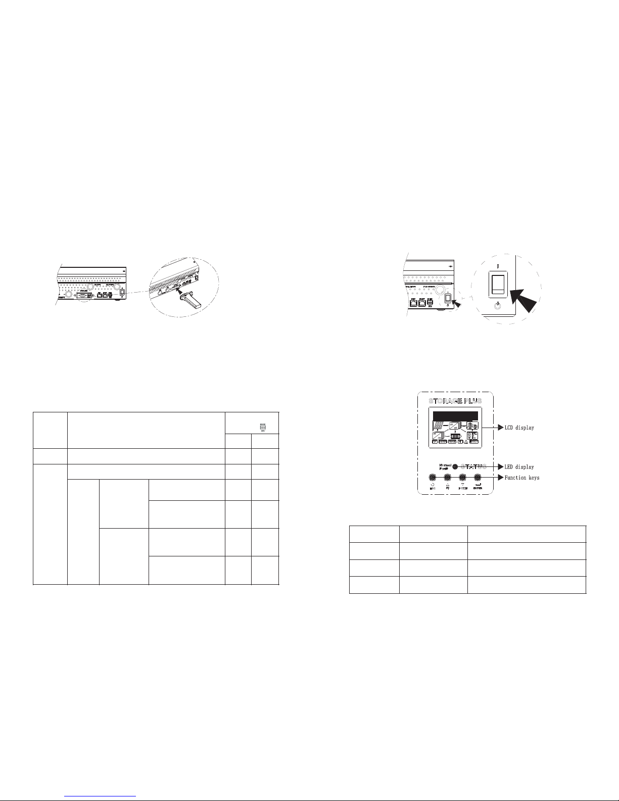
Operation 6
6.1.Power on/off
Once the u nit h as been pro perl y ins tall ed and the batte ries a re co nnec ted well,
simply p ress O n/Off swi tch (loca ted on the bu tton of the case ) to tu rn on t he un it.
Figure 6. 1
6.2.Operation and display panel
The oper atio n and d isplay pa nel, show n in be low chart , is on t he fro nt pa nel of the
invert er. It in clud es LC D display, in dic ator s, and func tion keys t o sho w the o pera ting
status a nd in put/ outp ut po wer in formati on.
Figure 6. 2
LED indi cato r:
LED i ndica tors
LED s tatus
Des cript ion
Gre en
Sol id on
Nor mal: In verte r worki ng well
Red
Fla shing
War ning : Wa rnin g, but st ill wor king
Red
Sol id on
Err or: In verte r stop wo rk
Table 6.1
Page 10

15
16
Buzzer :
Sta tus
Des cript ion
Bee ps ever y 3 secon ds
Inv erter i s in war ning st ate
Bee ps cons tantl y
Inv erter i s in erro r stat e
Table 6.2
Button s:
Fun ction K ey
Des cript ion
ESC
To exit s ettin g mode
UP
To go to pr evio us sele ction
DOW N
To go to ne xt sele ction
ENT ER
To conf irm the s elect ion in se tting m ode or en ter set ting mo de
Table 6.3
LCD disp lay:
Figure 6. 3
1. LCD display description
In t he fir st li ne of t he LCD, it displ ays th e war ning erro r code & curr ent statu s & set ting
item.
The curr ent st atus incl udes Norm al, Wa rn, E rror. More in fo abo ut er ror & warni ng
code and s ett ing it em pl ease refer to fol lowing pa ges
In t he sec ond l ine of the LCD, it disp lays i nput & output pa rame ter s and time of
invert er
Ite ms
Des cript ion
Vb/ Cb: xx. xV/ xxx %
Bat tery vo ltage /batt ery cap acity
Vpv : xxxV/ x xxV
PV vo ltage :PVA vol tage/ PVB vol tage
Ic_ pv: xx. x / xx.x A
PV ch arge cu rrent : PVA cha rge cur rent/ P VB char ge curr ent
Ppv : xxxx/ x xxxW
PV ch arge po wer: PVA c harge p ower/ P VB char ge powe r
AC_ In: xxx V/ xxHz
Volt age/f reque ncy of i nput AC
AC_ Out: xx xV/ xxH z
Volt age/f reque ncy of o utput A C
Ich r_ac: x x.xA
AC ch arge cu rrent
Ich r_all : xxx.x A
Total c harge c urren t
PL: x xxxW/ x xxxVA
Pow er of loa d
Per _Load : xxx%
Loa d perce ntag e
Epv _d: xxx x.x KWh
Dai ly PV gen erati on
Epv _a: xxx x.x KWh
Total P V gener ation
Ec_ d: xxxx .x KWh
Dai ly char ged cap acity o f batte ry
Ec_ a: xxxx .x KWh
Total c harge d capac ity of ba ttery
Ed_ d: xxxx .x KWh
Dai ly disc harge d capac ity of ba ttery
Ed_ a: xxxx .x KWh
Total d ischa rged ca pacit y of batt ery
20x x/xx/ xx xx:x x
Ti me
Ser No: xxx xxxxx xx
Ser ies num ber
Mod el: xxx xxxxx xx
Mod el
FW Ver sion: x xxx
Fir mware v ersi on
Table 6.4
Page 11

17 18
2. Display
Ite ms
Des cript ion
It pr esen ts batt ery cap acity. E ach int erval i ndica tes bat tery ca pacit y
lev el by 0-2 0%
Loa d power : Each in terva l indic ates lo ad leve l by 0-25 %
Ind icate s unit co nnect s to the ma ins or ge nerat or
Ind icate s unit co nnect s to PV mod ular. On e PV modu lar ico n
Ind icate s the DC/ DC(MP PT) cir cuit i s worki ng.
Ind icate s the DC/ AC inve rter ci rcuit i s work ing.
Ind icate s the WIF I circu it is wo rking .
Ind icate s the RS2 32 circ uit is w orkin g.
Ind icate s the RS4 85 circ uit is w orkin g.
Ind icate s the uni t is in sil ent mod e
Ind icate s the inv erter i s in war ning st ate
Ind icate s the inv erter i s in erro r stat e
Table 6.5
Ite ms
Des cript ion
Bat tery po wers th e load.
PV en ergy ch arges b atter y.
Uti lity en ergy ch arges b atter y.
PV an d utili ty ener gy char ge batt ery tog ether.
PV en ergy is c hargi ng batt ery whi le batt ery pow ers the l oad.
PV en ergy is c hargi ng batt ery whi le util ity pow ers the l oad.
Uti lity po wers th e load an d charg es batt ery.
PV en ergy an d utili ty char ge the ba ttery t ogeth er whil e utili ty
pow ers the l oad.
Onl y utili ty powe rs the lo ad.
Table 6.6
Page 12

19 20
Main men u
Submen u
Descri ptio n
Exit set ting m ode
/
Exit
AC Outpu t
Source
PV first
Solar en ergy p rovi des po wer to t he loads as
first pr iori ty. If solar en ergy i s not su ffic ient to
power al l conn ecte d loads, ba tter y ener gy will
supply p ower t he loa ds at the sam e time .
Utilit y (dur ing ut ility’s pow erin g load t ime)
pro vide s power to th e load o nly wh en anyone
condit ion ha ppen s:
- Solar en ergy i s not av ailable
- Batter y volt age dr ops to e ithe r low-lev el
warnin g volt age or the se ttin g poin t in
“Batte ry Low Vo lt”
UTI firs t
Utilit y (dur ing ut ility’s pow erin g load t ime)
will prov ide power t o the lo ad as fi rst prior ity.
Solar an d batt ery en ergy will p rovide pow er to
the load o nly wh en uti lity powe r is not
availa ble.
BAT fi rst
(defau lt)
Solar en ergy p rovi des po wer to t he load as
first pr iori ty. If solar en ergy i s not su ffic ient to
power al l conn ecte d loads, ba tter y ener gy will
supply p ower t o the lo ads at the sa me tim e.
Utilit y (dur ing ut ility’s pow erin g load t ime)
pro vide s power to th e load o nly wh en batter y
voltag e drops to eit her lo w leve l war ning
voltag e or the s etti ng point in “ Batt ery Lo w
Volt”.
UTI out st art
xxH
(defau lt 0H)
The time w hen ut ilit y start to po wer th e load .
Settin g rang e from 0 H to 23H .
UTI out en d
xxH
(defau lt 0H)
The time w hen ut ilit y end to powe r the lo ad.
Settin g rang e from 0 H to 23H .
Charge S ource
PV first
(defau lt)
Solar en ergy w ill ch arge batt ery as f irst
priori ty.
Utilit y (dur ing ut ility’s cha rgin g time ) will
charge b atte ry onl y when sola r ener gy is no t
availa ble.
LCD description:
After pr essi ng and hold ing E NTER b utton for 3 seco nds, the un it wi ll enter se tting
mode. Pr ess “U P” or “ DOWN” but ton t o sele ct se ttin g program s. And then , pres s
“ENTER ” butt on to c onfirm th e sel ecti on or E SC button t o exi t.
Main men u
Submen u
Descri ptio n
Charge S ource
PV & UTI
Solar en ergy a nd uti lity (dur ing ut ilit y’s
chargi ng tim e) cha rge the bat tery a t the sa me
time.
PV Only
Solar en ergy c harg es the batt ery on ly.
UTI Char ge Sta rt
xxH
(defau lt 0H)
The time w hen ut ilit y start to ch arge t he
batter y. Se ttin g rang e from 0 H to 23H .
UTI Char ge End
xxH
(defau lt 0H)
The time w hen ut ilit y end to char ge the
batter y. Se ttin g rang e from 0 H to 23H .
PV Input M ode
Parall el
Two so lar in put pa rall el.
Indepe nden t
(defau lt)
Two so lar in put in depe nde nt.
AC Input M ode
APL:90 280VAC
(defau lt)
Common a ppli cati on.
UPS:17 0-
280VAC
UPS appl icat ion.
AC Outpu t Volt
208VAC
AC outpu t volt age 20 8VAC.
230VAC
(defau lt)
AC outpu t volt age 23 0VAC.
240VAC
AC outpu t volt age 24 0VAC.
AC Outpu t Freq
50Hz
(defau lt)
AC outpu t frequenc y 50Hz .
60Hz
AC outpu t frequenc y 60Hz .
OverLo ad Res tart
YES
(defau lt)
Enable a uto restar t when o verl oad occur s.
NO
Disabl e auto resta rt whe n over load occu rs.
Swith to U TI
If overl oad oc curs i n battery d isch arge m ode,
utilit y provides p ower t o the lo ad.
Page 13

21 22
Main men u
Submen u
Descri ptio n
OverTemp R esta rt
YES
(defau lt)
Enable a uto restar t when t empe rature occurs .
NO
Disabl e auto resta rt whe n temp erature
occurs .
Buzzer O N/OF F
ON
(defau lt)
Alarm on .
OFF
Alarm off .
Batter y Type
Lithiu m
Lithiu m batt ery.
Lead_A cid
Lead_A cid.
Custom
Lead_A cid
Self-d efin ed Lea d_Acid.
Max char ge Cur r
xxxA
(defau lt
70A)
If batte ry typ e is sel ected as le ad aci d batt ery,
this prog ram can be se t up. SP F500 0: Settin g
range is f rom 10A to 130 A.
SPF300 0: Set ting r ange is from 1 0A to 100A.
Bulk cha rge Vol t
xx.xV
(defau lt
56.4V)
If batte ry typ e is sel ected as “s elf- defi ned
Lead_A cid” , this p rogr am can b e set up.
Settin g rang e is fro m 50.0 V to 57. 4V.
Float ch arge Vo lt
xx.xV
(defau lt
54V)
If batte ry typ e is sel ected as “s elf- defi ned
Lead_A cid” , this p rogr am can b e set up.
Settin g rang e is fro m 50~5 6V.
Batter y Low Vol t
xx.xV
(defau lt
46.4V)
Settin g volt age po int back to b atte ry mod e
when sel ecti ng“B AT firs t” or “PV fir st”.
Settin g rang e is fro m 44.4 ~51. 4V.
COM Addr
xxx
Setup co mmun icat ion addres s
System T ime
xxxx/x x/xx
xx:xx: xx
Setup th e syst em tim e
Table 6.7
Error description:
Err or cod e
Des crpti on
Bat v oltag e high
Bat tery vo ltage i s high
Ove r Temp erat ure
Ove r tempe ratur e
Ove r Load
Ove r load
Ove r Curre nt
Ove r curre nt
MOV b reak
MOV f ailed
Li- Bat Ove r Load
Ove r Load wi th Lith ium bat tery
Err or: 10 1
M3 fa iled to c ommun icate w ith DSP
Err or: 10 2
The s ample f rom M3 an d DSP of t he batt ery vol tage is i ncons isten t
Err or: 10 3
Buc k over cu rrent
Err or: 10 4
BMS f ault
Err or: 10 5
BMS f ault fr om bat tery
Err or: 11 6
Rev erse po larit y prote ctio n diode f ailed
Err or: 11 7
Bus S oft-s tart fa iled
Err or: 11 8
DC- DC boot f ailed
Err or: 11 9
DC in jecti on outr ange
Err or: 12 0
Fai led to de tect cu rrent
Err or: 12 1
Com munic ation f ailed b etwee n DSP and M 3
Err or: 12 2
Bus v oltag e is too hi gh
Err or: 12 7
AC ou tput vo ltage i s too hig h
Table 6.8
Page 14

Warn description:
Ite m
Des crpti on
War n:Fa n Warni ng
Fan f ailed t o turn
War n: Bat L ow
Bat tery vo ltage l ow
War n: Ove r Load
Ove r load
War n: Li- Bat OL
Ove r Load wi th Lith ium bat tery
War n: Ove r Temp
Ove r tempe ratur e
War n: 103
Fai led to re ad EEP ROM
War n: 104
Fir mware v ersi on mism atche d
War n: 105
Fai led to wr ite EEP ROM
War n: 106
War ning o f BMS
INV ERTER M ODEL
SPF 3000
Low L oss Fre quen cy
40± 1Hz
Low L oss Ret urn Fre quenc y
42± 1Hz
Hig h Loss Fr eque ncy
65± 1Hz
Hig h Loss Re turn F reque ncy
63± 1Hz
Tran sfer T ime
10m s(UPS ) 20ms( APL)
Pow er dera ting:
Whe n AC inpu t volta ge
dro ps to 17 0V depe nding
on mo dels, t he outp ut
pow er and ch arge po wer
wil l be dera ted.
Table 6.9
Table 7.1
Specifications7
Line Mode Specifications:
Bat Mode Specifications:
INV ERTER M ODEL
SPF 3000
Rat ed Outp ut Powe r
2.4 KW/3K VA
Out put Volt age Wav eform
Pur e Sine Wa ve
Out put Volt age Reg ulati on
230 ±5%VAC /208VA C/240 VAC
Out put Volt age Fre quen cy
50H z(def ault) /60Hz
Pea k Effic ienc y
93. 5%
Ove rload P rotec tion
10s (110% -150% ) 5s(15 0%-20 0%)
Bat tery Type *
Li/ L ead_A cid
MAX D ischa rging D epth
5% SO C(li)
Bat tery Vol tage Ra nge
46. 4V-57. 4V(Li ) /38.4 V-60V( Lead_ Acid)
23 24
Inp ut Volta ge Wave form
Sin usoid al(ut ility o r gener ator)
Nom inal In put Volt age
230 VAC
Low L oss Volt age
170 ±5VAC( UPS) 90 ±5VAC( APL)
Low L oss Ret urn Vol tage
180 ±5VAC( UPS) 10 0±5VAC (APL)
Hig h Loss Vol tage
280 ±5VAC
Hig h Loss Re turn Vo ltage
270 ±5VAC
Max A C Input Vo ltage
300 VAC
Max A C Input Vo ltage
50H z/60H z(Aut o detec tion)
SPF 3000
SPF 5000
SPF 3000 PL US
INV ERTER M ODEL
SPF 5000
SPF 3000 PL US
SPF 5000
4KW /5KVA
SPF 3000 PL US
4KW /5KVA
3KW /3KVA
Page 15

Bat Mode Specifications:
INV ERTER M ODEL
SPF 3000
Col d Start Vo ltage
47V DC(Li ) /46VD C(Lea d_Aci d)
Hig h DC Cut- off Volt age
58V DC(Li ) /60VD C(Lea d_Aci d)
Hig h DC Reco very Vol tage
57. 4VDC( Li) /58 VDC(L ead_A cid)
Low D C Warni ng Volt age(o nly Lea d_Aci d)
@ loa d < 20%
@ 20% ≤ l oad < 50%
@ loa d ≥ 50%
44. 0VDC
42. 8VDC
40. 4VDC
Low D C Warni ng Ret urn Vol tage( only
Lea d_Aci d)
@ loa d < 20%
@ 20% ≤ l oad < 50%
@ loa d ≥ 50%
46. 0VDC
44. 8VDC
42. 4VDC
Low D C Cut-o ff Volta ge(o nly Lea d_Aci d)
@ loa d < 20%
@ 20% ≤ l oad < 50%
@ loa d ≥ 50%
42. 0VDC
40. 8VDC
38. 4VDC
Low D C Warni ng SOC (only L i)
10% S OC
Low D C Cut-o ff SOC( only L i)
5% SO C
No Lo ad Powe r Consu mptio n
<5 0W
INV ERTER M ODEL
100 A
MAX C hargi ng Volta ge
57. 4VDC
INV ERTER M ODEL
SPF 3000
PVA MA X Power
175 0W
PVB M AX Powe r
175 0W
PVA MA X input c urren t
30A
PVB M AX inpu t curre nt
30A
Total P V MAX cha rge cur rent
70A
Eff icie ncy
98. 0% MAX
Max . PV Arra y Open Ci rcuit Vo ltag e
145 VDC
PV Ar ray MPP T Voltag e Range
60- 115VD C
Table7.3
General Specifications:
INV ERTER M ODEL
SPF 3000
Saf ety Cer tific ation
CE
Ope ratin g Temp erat ure Ran ge
0℃-5 5℃
Sto rage Temp eratu re
-1 5℃-60℃
Qua lity Gu arant ee Peri od
3 yea rs
Saf ety Cer tific ation
Ove r Temp erat ure
Ove r Voltag e
Out put Sho rt
Ove r Load
Noi se
<4 8dB
Dim ensio n(D*W *H,mm )
470 x440x 120
Net W eigh t,kg
Table7.2
Table7.4
Note: Ma x cha rge an d dis char ge po wer an d cur rent r est with ba tter y's c apac itance, if
batter y type is Lit hium batt ery.A nd som e loa d with indu ctan ce wi ll be l imit ed.
PV Mode Specifications:
25 26
SPF 5000
SPF 3000 PL US
SPF 3000 PL USSPF 5000
130 A
100 A
SPF 5000
SPF 3000 PL US
10K G
12. 5KG
440 x390x 120
Page 16

Table8.1
8 Trouble Shooting
Pro blem
Explan atio n/Po ssible
cause
What to do
Unit shu ts dow n
automa tica lly du ring
startu p process.
The batt ery vo ltag e is too
low
1. Re-ch arge b atte ry.
2. Repla ce bat tery.
No re spon se after
power on .
1.The ba tter y volt age is
far too lo w.
2.Batt ery po lari ty is
connec ted revers ed.
1. Check i f batt erie s and the
wiring a re connect ed wel l.
2. Re-ch arge b atte ry.
3. Repla ce bat tery.
UTI out en d
Input pro tector is t ripp ed
Check if A C breaker is
trippe d and AC w irin g is
connec ted we ll.
Insuffi cient qua lity o f AC
power. (Sh ore or
Genera tor)
1. Check i f AC wires are too
thin and /or to o long .
2. Check i f gene rato r (if
applie d) is wo rkin g well or if
input vo ltag e rang e setting
is correc t. (Appli ance )
Set “Sol ar Fir st” as t he
priori ty of ou tput s ourc e.
Change o utpu t sour ce
priori ty to Ut ilit y first.
When the u nit is
turned o n, int ern al
rel ay is sw itched on
and off rep eate dly.
Batter y is dis conn ected.
Check if b atte ry wir es are
connec ted we ll.
27 28
Manufacturer Warranty 9
This cer tifi cate represen ts a 3 ye ar wa rran ty for the Growat t pro duct s listed be low.
Posses sion o f thi s certifi cate v alidate s a sta ndar d fact ory w arra nty o f 3 yea rs fro m the
date of pu rcha se.
War rant ed pro ducts
This war rant y is ap plicabl e sole ly to t he fo llow ing p rodu cts:
Gro watt SPF3 000
Gro watt SPF5 000
Gro watt SPF3 000 PLUS
Limite d Prod uct Wa rran ty
(Appli cabl e under nor mal a ppli cati on, i nsta llat ion, use and ser vice cond itio ns)
Gro watt prov ides a non- tran sfer able warr anty for a p erio d of 3 ye ars f or the abov e
listed p rodu cts. This s tandard w arra nty valid ates f rom t he dat e of cu stomer pu rcha se,
and does n’t ex ceeding 3 year s from t he da te of p urch asin g as sh own i n the proof o f
Purchas e fro m the Origi nal purcha ser.
Gro watt shal l have no obliga tion t o kee p prod uct w arra nty, if a ny of t he fo llow ing
situat ions o ccurs:
·Misuse , abus e, ne glec t or ac cide nt;
Altera tion , improper inst alla tion or applic atio n;
Unauth oriz ed modifi cati on or a ttem pted repa irs;
Insuffi cient ven tilatio n of th e prod uct;
Bre akin g of th e ori gina l man ufac ture rs seal;
Non-ob serv ance of Gro watt inst alla tion and ma inte nance ins tructio n;
Failure to obs erve the appli cabl e safety re gula tion s;
Power fa ilur e surges, f lood, fir e, acc ident, fo rce majeu re, ex plos ion, terr oris t act,
extreme weat her condi tion s or ot her unreasona ble ci rcum stances ;
The warr anty shal l also ceas e to ap ply i f the product can not b e corr ectl y ide ntif ied a s
the prod uct of Growatt. Warra nty cl aims will not be hono red if the ty pe of s eria l
·
·
·
·
·
·
·
Page 17

Appendix10
The foll owin g cha rt is t he invert er opt ional app endi x lis t, if t here i s a nee d ple ase
contac t the G rowatt New Ener gy Techn ology Co. , Ltd o r dea ler or ders .
Nam e
Des cript ion
Shi neWi Fi
COM i nterf ace by wi -fi
Shi ne3G
COM i nterf ace by WC DMA or GP RS
Shi neLin k(Shi neLan Box+S hineR FStic k)
COM i nterf ace by RF a nd Lan
Shi ne WebB ox
Dat a recor d by Rs48 5
Table10. 1
The foll owin g cha rt is a ppro xima te Back-u p time tabl e:
Mod el
Loa d(VA)
Bac kup Ti me
wit h 48Vdc 1 00Ah( min)
Bac kup Ti me
wit h 48Vdc 2 00Ah( min)
3KVA
300
105 4
210 7
600
491
105 4
900
291
668
120 0
196
497
150 0
159
402
180 0
123
301
210 0
105
253
240 091219
270 071174
300 063155
5KVA
500
613
128 8
100 0
268
613
150 0
158
402
200 0
111
271
250 090215
300 076182
350 065141
400 050112
450 044100
500 04090
Note: Ba ck up t ime depen ds on t he qua lit y of the batt ery, ag e of ba tter y and t ype o f
batter y.
Specif icat ions of bat teri es ma y vary depe nding on di ffer ent manuf actu rers .
Table10. 2
29
30
Page 18

Contact11
If y ou hav e tec hnic al proble ms abo ut ou r prod ucts, con tact the Gr owat t Ser vice line o r
dealer. We n eed t he follow ing infor mati on in o rder t o provide y ou wi th the nece ssar y
assist ance :
1. M achi ne Se rial n umber
2. M achi ne mo dule i nformat ion
3. M achi ne co mmun icat ion m ode
4. M achi ne fa ult in formati on cod e
5. M achi ne Di spla y content
6. T he man ufa cturer and mode l of th e batt ery
7. B atte ry ca paci ty and conn ecti on mo de
31
SHENZH EN GRO WATT NE W ENERGY TE CHNO LOGY CO., LTD
No.28 Gu angm ing R oad, Shiy an Str eet, Bao' an Distri ct,
Shenzh en, P.R.Chin a
T: + 86 755 274 7 194 2
E: s ervi ce@g inverte r.c om
W: www.gi nver ter.com
 Loading...