

Growatt SPA 1000TL BL, SPA 2000TL BL, SPA Series, SPA 3000TL BL Installation & Operation Manual
Page 1
GR- UM- 152 -A-00
SHENZHEN GROWATT NEW ENERGY TECHNOLOGY CO.,LTD
No.28 Guangming Road, Shiyan Street, Bao'an District, Shenzhen,
P.R.China
T: +86 755 2747 1942
E :service@ginverter.com
W :www.ginverter.com
Installation
Operation Manual
&
Page 2

List
1.1 O vervi ew
1.2 Tar get Gro up
1 Intro duction
2 Safet y
2.1 S afety O vervi ew
2.2 S ymbol s Expla natio n
3.1 F uncti on
3.2 M odels
3.3 A ppera nce
3.4 D imens ions
3.5 N amepl ate
3.6 S torag e
3 Produ ct Introductio n
4 Unpac king
5 Insta llation
5.1 B asic In stall ation R equir em ent s
5.2 Tools an d Instr uctio ns
5.3 I nstal latio n Instr uctio ns
5.4 S ystem C onnec tion Mo del
Page 3

6.1 C ommis sioni ng of SPA
6.2 O perat ion Mod es
6.3 C ountr y Setti ng
6.4 D ispla y and But ton
6.5 C ommun icati on
12. 1 Disma ntlin g the Ene rgy Sto rage
12. 2 Packi ng the SPA I nve rte r
12. 3 Stori ng SPA Inv ert er
12. 4 Dispo sing of t he SPA Inv ert er
13. 1 SPA Seri es En erg y Sto rag e
Mac hine Pr odu ct Sp eci fic ati on
13. 2 To rque
13. 3 Appen dix
6 Commi ssioning
12 Deco mmissioning
7 Sta rt-up a nd Shut Dow n
SPA System
13 Prod uct Speci ficatio n
7.1 S tart- up the SPA S yst em
7.2 D iscon nect th e SPA Syst em
8 Atten tion of t he Instal lation
14 Cont act
9 Trouble Shooting
10 EU Dec laration of
Confo rmity
11 Warr anty
Page 4
1 Introduction
1.1 Ove rview
1.2 Target Grou p
Thi s ma nua l wil l prov ide detai led pro duc t informatio n an d ins tal lat ion ins tru cti ons for
use rs o f the SPA ser ies of AC coupled from Shenzhe n Go wat t New Ener gy Technology
Co. Ltd. (he rei naf ter ref erred to as Growa tt) . Plea se read th is manu al car efu lly bef ore
usi ng this p roduc t, an d kee p thi s man ual i n a pla ce th at is e asy f or in sta lla tio n, op era tio n,
and m ainte nance p erson nel to ob tain.
Any cha nge s to thi s ma nua l by G rowat t wi ll n ot be not ified to t he u ser. You may ref er t o
the G rowat t web sit e ( ) for t he most u pdate d versi on. www. ginve rter.c om
2 Safety
2. 1 Saf ety Overv iew
•
to fai lure to ins tal l acc ordi ng to the inst ruc tio ns in thi s man ual , Growa tt rese rve s the
rig ht not to g uaran tee the q ualit y.
•Al l ope rat ions and wir ing must be pe rfo rme d by tra ine d and pro fes sio nal el ect ric al
tec hnici ans.
•Wh en i nst all ing , do not touch the oth er part s of the ins ide of the chas sis exce pt t he
ter minal b lock.
•Al l elect rical c onnec tions m ust com ply wit h local e lectr ical sa fety st andar ds.
•If t he equ ipm ent re qui res ma int ena nce , plea se co nta ct the lo cal des ign ate d syst em
ins talla tion an d maint enanc e perso nnel.
•Th e u se of equi pme nt for gri d conn ect ion req uir es perm iss ion fro m t he loc al powe r
sup ply dep artme nt.
Ple ase r ead this man ual caref ully bef ore insta llati on. I f t he e quipm ent i s d ama ged due
Han dling:
Ele ctric al conn ectio ns:
Rep air and r epl ace men t:
•SPA is heavy, ple ase be ca ref ul to c arr y it ou t to pre ven t it fr om fa lling
off.
•Mu st be ope rated b y a train ed prof ess ion al el ect ric al te chn ician and
fol low thi s manua l and loc al regu lat ion s.
•Do n ot touc h the inv erter a t will be cause o f high vo ltage d anger.
•Do n ot plac e flamm able or e xplos ive mat erial s aroun d the S PA.
•It mus t be op era ted b y a trai ned p rof ess ion al el ect ric al te chn ici an an d
adh ere to th is ma nua l.
•Be s ure to di sco nne ct th e bat ter y and G rid f or at l east 5 minutes
bef ore ope rat ion t o avo id da nge r. Plea se pe rfo rm al l ope rat ion s aft er
pow er off.
•Ri sk of hig h volta ge, be ca reful o f ele ctr ic sh ock .
•An AC circ uit break er mu st be ins tal led for each SPA , a nd mul tip le
SPA ar e proh ibite d from sh ari ng.
•Th e cab le is thi ck. Do no t sha ke it tig htl y af ter t igh ten ing the cab le
ter minal s. Make su re that the terminals are we ll con necte d befo re
sta rting SPA. In case the ter min al is loo se, it will cau se over hea tin g
dam age.
•Pl ease co nfirm t he posi tive an d negat ive pol es befo re conn ect ing t he
bat tery to t he SPA.
For inverters that are n o longer in o per ation i n th e fu ture , users n eed
to pr ope rly d isp ose o f the m.
1
2
Ple ase rea d thi s man ual c arefull y befor e ins tal lat ion . If th e equ ipm ent i s
not d amage d accor din g to th e ins tru cti ons i n thi s manual, Grow att
res erv es th e rig ht no t to gu ara nte e the q uality.
WAR NIN G
CAU TION
WAR NIN G
DAN GER
DAN GER
DAN GER
WAR NIN G
WAR NIN G
SPA must be ins tal led by a prof ess ion al e lectr ician who i s q ual ifi ed f or t he relevant par t
of the certifica tion. By rea din g this man ual in det ail, the installer ca n install the SPA
ser ies c orr ect ly a nd qu ick ly, a nd can p erf orm tr oub leshooting a nd com mun ica tio n
sys tem con struc tion.
If the re are an y problems durin g the instal latio n p roces s, the in sta lle r can log on to
to lea ve a m essag e or ca ll c ustomer ser vic e ho tli ne +86 07 55 2 747 1
942 .
www. ginve rter.c om
Bef ore pro cee din g with the insta llati on, mak e sure th at th e SPA do es
not h ave any e lectr ical co nnect ions.
•
env ironm ent , spa cin g, et c.
•In stall t he SPA in a dr y and v ent ila ted p osi tio n, ot herwise the SPA may
be af fec ted .
•Pl ease re fer t o thi s man ual f or th e ins tal lation proce dur e. Pl eas e
rea d it ca ref ully before in sta lla tio n.
Ple ase ref er to t he co nte nts o f thi s man ual f or th e installati on
Ins talla tion:
Page 5
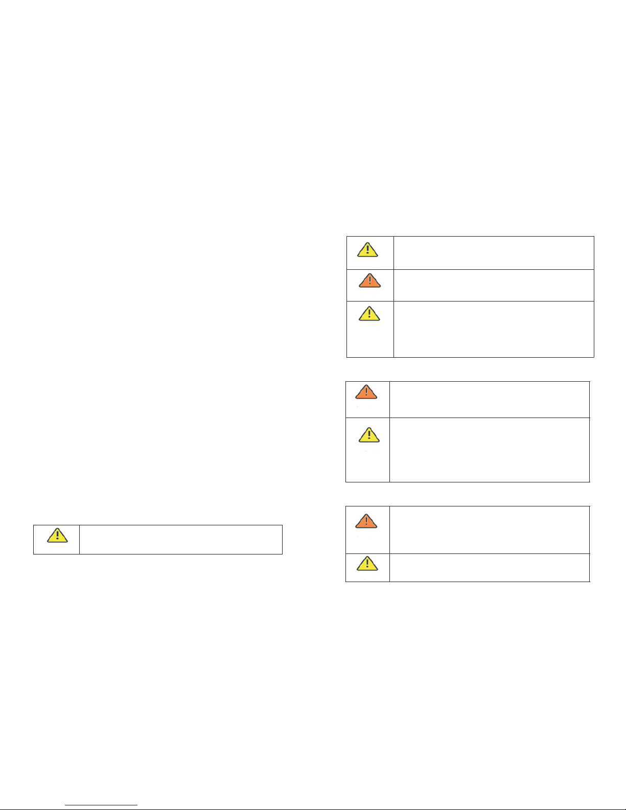
2. 2 Sym bols expl anati on
Sym bol
Des cript ion
Dan ger of hi gh volt age and e lectr ical sh ock.
Dan ger of ho t surfa ce.
SPA wi ll be com e hot d uri ng op era tio n to avoid contact du ring
ope ratio n.
Cau tion: R isk of da nger.C aut ion : Risk of danger.
Dan ger of hi gh volt age
The re is res idu al vo ltage existi ng in SPA af ter t urn ed of f, pl eas e
wai t at leas t 5 minut es befo re you op en th e upp er li d or th e
DC li d.
Con necti ng the pr ote cti ve ea rth ( PE) c abl e.
Rem ind ope rator s refer t o the d ocu men ts su ppl ied w ith S PA.
SPA sh oul d not b e dis pos ed as h ous eho ld waste.
Kee p dry!
The p ackag e /prod uct m ust b e protected fr om ex ces siv e
hum idity a nd be sto red und er co ver.
CE Ma rk.
SPA co mpl ies w ith t he requir eme nts o f the a ppl ica ble C E
gui delin es.
4
3
Product Introduction 3
3.1 Fun ction
3.2 Mod els
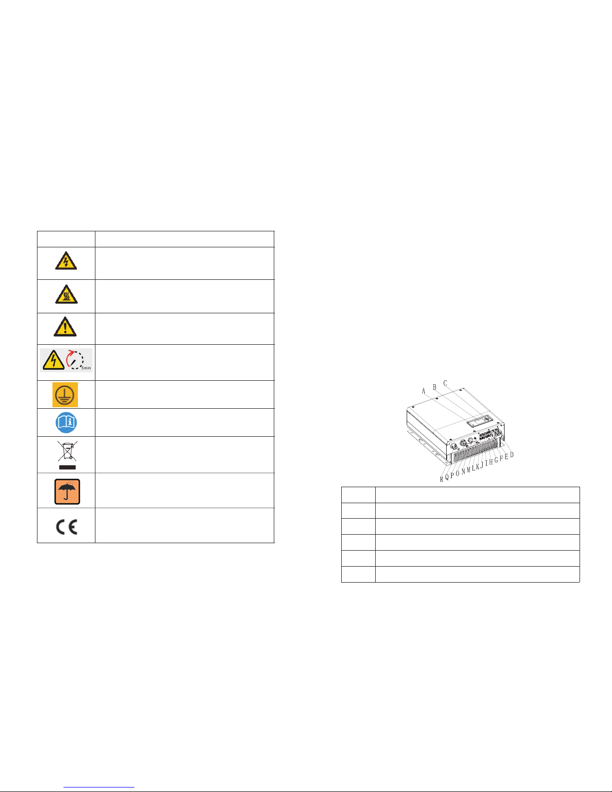
3.3 App erance
SPA ser ies are th e AC Coupled inve rte r whic h can st ore en erg y into batte ry with or
witho ut exist ing grid -ti ed in ver ter s yst em. S PA c an be u sed to o pti miz e se lfcon sumpt ion、st ored in th e bat ter y or f eed i nto p ublic gri d. It a lso can p rovi de pow er fo r
eme rgenc y use dur ing the g rid los t by usin g the ene rgy fro m the b att ery.
Thi s docum ent inv olves t he foll owing p roduc t mod el:
•SPA 1 000 TL BL
•SPA 2 000 TL BL
•SPA 3 000 TL BL
Table 3.1 Des ignat ion exp lanat ion of th e SPA seri es.
Ser ies nam e •SPA-S ing le Ph ase A C Cou ple d inv ert er.
Pow er leve l •1000 TL-th e power l evel is 1 kW.
•20 00TL- the pow er leve l is 2kW.
•30 00TL- the pow er leve l is 3kW.
Bat tery •B L-be us ed with l ow volt age bat tery.
Pos ition
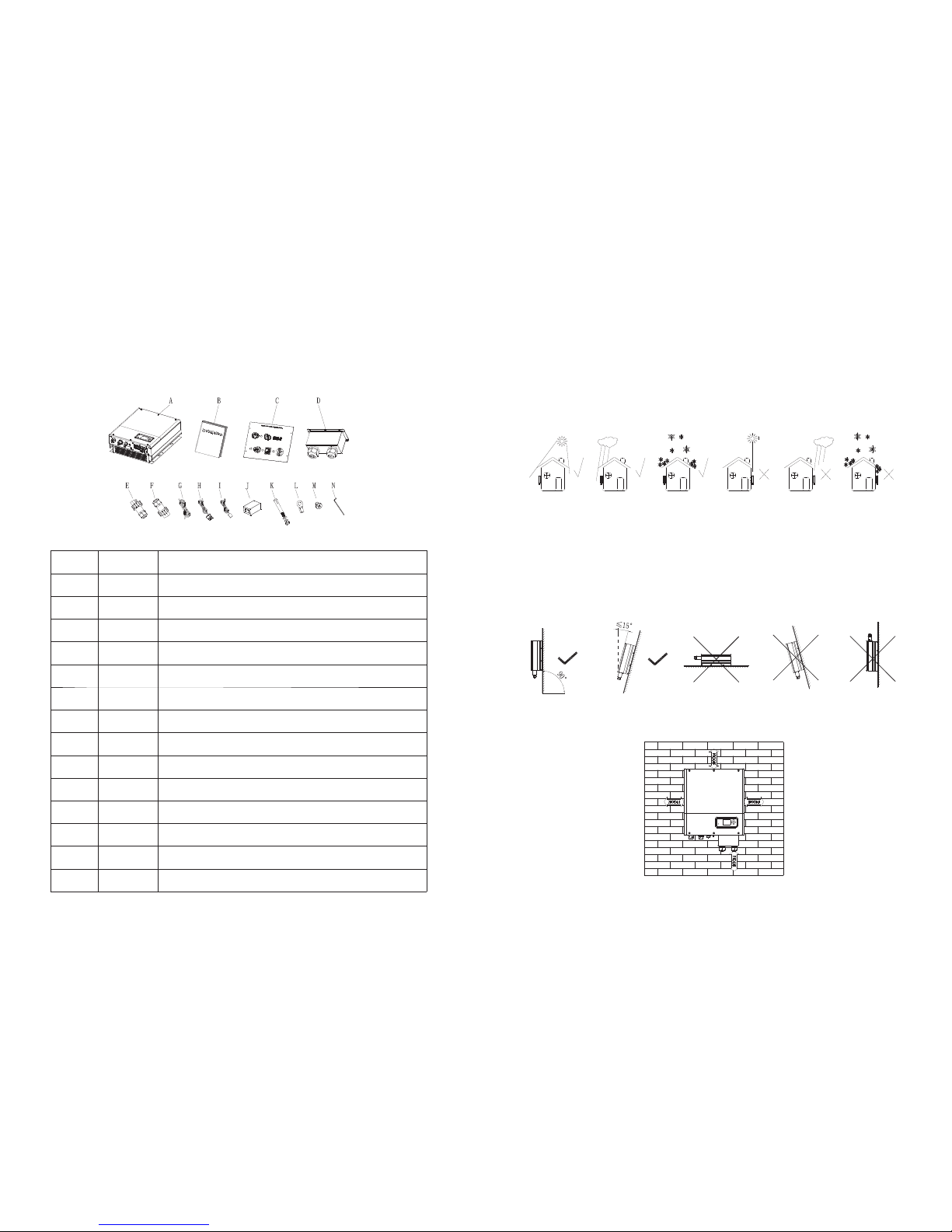
Des cript ion
A
LED o f statu s displ ay
B
LCD s creen
C
Fun ction b utton
D
Bat tery te rmina l
E
DIP s witch (set s afe ty st and ard )
Fig 3 .1
Page 6
6
5
F
RS 48 5 commu nicat ion int erfac e of Lith ium bat tery
G
CAN c ommun icati on inte rface o f Lithi um batt ery
H
MET ER inpu t termi nal
I
NTC :Lead -acid t emper ature s ens or te rmi nal
J
CT 2( C T termi nal use f or meas ure oth er in ver ter p owe r)
K
RJ 45 i nterf ace of DR Ms(us ed only i n Austr alia)
L
CT 1( C T termi nal use f or meas ure gri d pow er)
M
ANT ENNA
N
USB i nterf ace
O
RS 23 2 inter face
P
EPS o utput (off gr id co nne cti on)
Q
Gro und P oin t
R
AC Gr id (on gr id conn ectio n)
3.4 Dim ensions
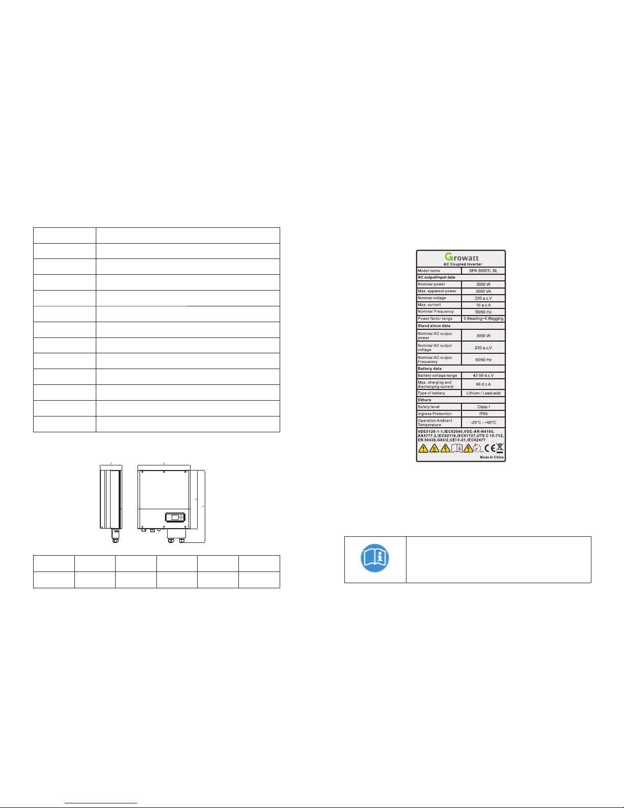
3.5 Nam eplate
3.6 Sto rage
Dim ensio ns
A(m m)
B(m m)
C(m m)
D(m m)
Wei ght (kg )
SPA Se rie s
474
428
178
590
17
Nam eplat e conta ins the f ollow ing inf ormat ion. Take S PA3 000 a s an example:
Table 3 .1
Table 3 .2
Fig 3 .2
Fig 3 .3
•
pla ce.
•Th e store d tem per atu re range is - 25 ° C - +60 ° C, s torag e humid ity ran ge is 0 ~ 95% .
•If a l arge nu mber of S PA Se rie s need to be store d, do n ot ex cee d sev en la yer s.
•Lo ng-te rm SPA Ser ies n eed t o be te ste d bef ore in stall ation .
The SPA Series is be st st ore d in th e ori ginal packaging a nd pl ace d in a venti lated and d ry
Aft er the st orage t ime exc eeds on e month , the tim e and dat e of
the f actor y setti ng of the S PA Se rie s may be incorre ct. B efo re th e
SPA Se rie s is co nne cte d to th e gri d, th e rela ted s ett ing s nee d to
be ma de. For t he spec ific se tting m ethod , pleas e refer t o 6.4 .3 to
set t he time a nd date o f the SPA Se rie s.
Page 7
7
8
4 Unpacking
Installation 5
Ple ase che ck whet her ext erna l dam age to the goods befo re unpa cki ng. A fte r unp ack ing ,
Ple ase che ck whe the r t he unit dama ge or m iss ing part s, If i t i s happen, P lea se con tac t
wit h suppl ier.
SPA se rie s and a cce sso rie s as fo llo ws:
Ite m
Num ber
Des cript ion
A1SPA Se rie s(we d escri be this s eries a s “SPA” as b elo w )
B
1
Use r Manua l
C
1
Pap er boar d(i nsta llati on guid e)
D
1
Wat erpr oof c ove r
E
1
Onl ine Gri d Conne ctor
F
1
Off lin e Grid C onnec tor
G
1
Com munic ation c able
H2Cur rent Se nso r from g rid to lo ad and fr om gr id to in verte r
I
1
Lea d-aci d batte ry temp eratu re sens or
J
1
RJ 45 c onnec tor
K
4
M6 se tscre w
L
2
Bat tery po wer ter minal
M
6
Scr ew
N
1
Hex s crewd riv er
Fig 4 .1
Table 4 .1
5.1 Bas ic installatio n requi remen ts
•
•Th e insta llati on loca tion mu st matc h the siz e of the SPA s eri es.
•Do not ins tall the inv ert er on a bu ilding c ons tru cte d of f lam mab le o r non -heat res ist ant
mat erial s.
•SPA s eri es' s deg ree of prot ect ion i s IP6 5 and c an be i nst all ed in doo rs or o utd oor s. Pl eas e
ref er to t he be low :
The i nstal latio n locat ion mus t be suit able fo r SPA seri es' s wei ght f or a lo ng pe rio d tim e.
•
bet ween SPA s eri es an d bat ter y sho uld n ot be m ore th an 1. 5m.
•In ord er to pre ven t the SPA f rom r edu cin g the out put pow er due to ove rhe ati ng, please
do no t expos e the SPA to d ire ct su nlight.
•Th e ambie nt temp eratu re shou ld be - 25℃ ~6 0 ℃.
•Th e humid ity of th e insta llati on envi ronme nt sh oul d be be twe en 0~ 95% .
•SPA ser ies can be m oun ted on a p lane t hat is til ted ver tic all y or bac kwa rds. Ple ase ref er
to th e below :
Bat tery inst all ati on optio n is not far away from the posi tio n of SPA ser ies , the leng th
Fig 5 .1
Fig 5 .2
•
to pr ovi de ad equ ate s pac e for S PA seri es, P lea se re fer t o bel ow:
In orde r to e nsu re m ach ine can run n orm all y an d ea sy to ope rat e, p lea se pay att ent ion
Fig 5 .3
Page 8
10
9
•
cab les.
•Do n't ins tall th e machi ne in the l iving a rea.
•Be s ure tha t the m ach ine i s out o f the c hil dren 's re ach .
•Taki ng the bat ter y fixin g s pac e int o accou nt, abou t the dimens ions ple ase ref eren ce
use r manua l.
•Th e Inf lam mable a nd e xpl osi ve d ang ero us g ood s mu st n ot be p lac ed a round b att ery in
cas e of caus e serio us dang er.
Do not ins tal l the m ach ine nea r telev ision ante nna or any oth er a ntenn as an d an ten na
1 2 3 4 5
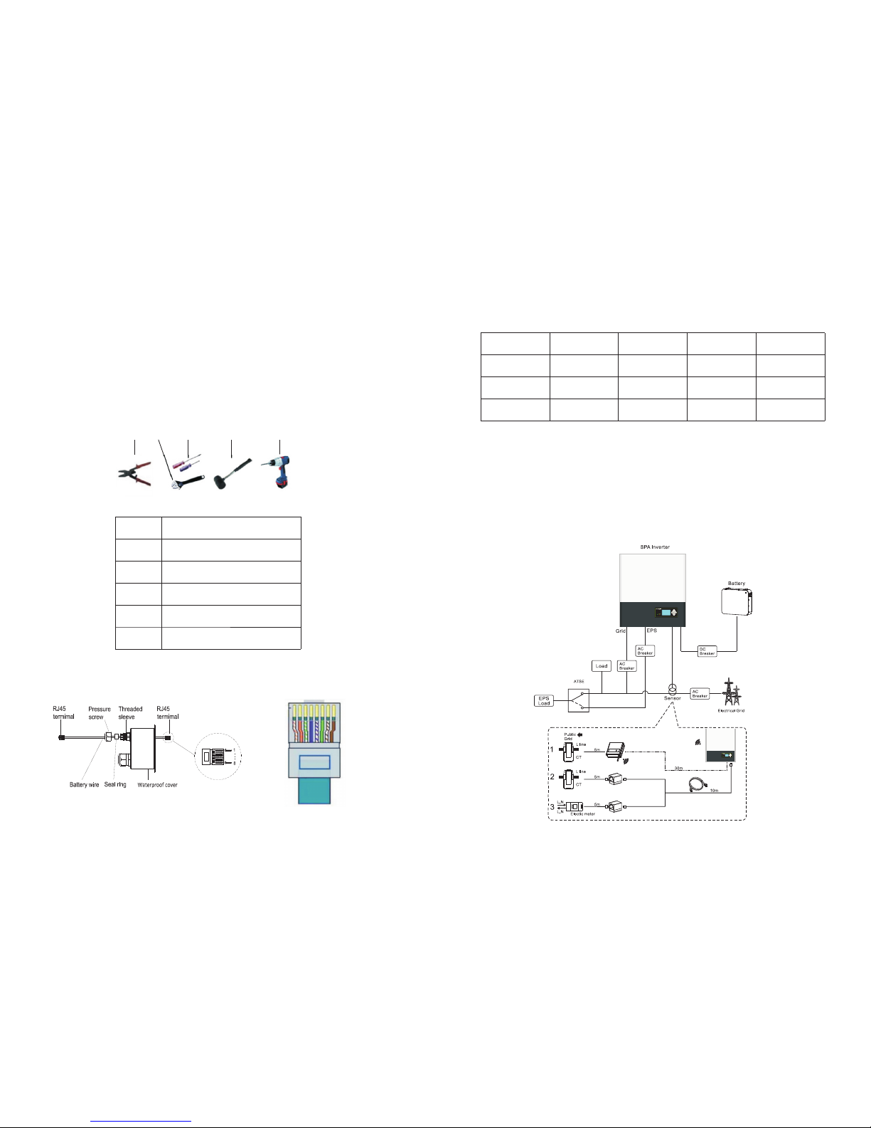
5.2 Tool s and ins trume nts
5.3 Ins tallation Inst ructi ons
5.3 .1 Atte ntion L ayout
No.
Des cript ion
1
Pre ss ba tte ry te rmi nal c onn ect or
2
Uns crew nu t
3
Uns crew sc rew
4
Kno ck expl osion b olt
5
Dri ll hole s on the wa ll
Fig 5 .4
Fig 5 .5
Fig 5 .6
Table 5 .1
LAN l ine RJ4 5 seque nce as fo llow:
PIN1234
Col or
Whi te oran ge
Ora nge
Whi te gree n
Blu e
PIN5678
Col or
Whi te blue
Gre en
Whi te brow n
Bro wn
LAN l ine 1-8 c olors a s below :
The re're t hree t ype s of s ens ors for t he u se of SPA Serie s. One is wi red cu rren t sens or, th e
oth er one is meter sensor or SP-CT ,if you choose wired s ens or or m ete r . Bef ore i nst all ing
you s hou ld know som eth ing that as b elo w: The c abl e of wir ed sen sor a nd met er is
sug geste d not long er t han 1 5 m ete rs. So you need to con sid er t he le ngt h b etween SPA
Ser ies wit h c omb ine r box for the sen sor shou ld be i nst all ed in the liv e line . An d i f you
ins talle d SP-CT f or sens or, Dist anc e reco mme nde d not m ore t han 3 0 met ers.
The i nstal latio n layou t of ener gy stor age mac hine at h ome as fo llowi ng:
Table 5 .2
Fig 5 .7
Page 9
12
11
NOT ICE:
•
•Th e curr ent sen sor dir ection can't be rever sed , pl eas e fo llo w th e ar row dire cti on. Ref er
to 5. 4.3&5 .4.6.
•Th ere are 3 typ es of sen sors, th e def aul t on e is CT wit h cab le, w irele ss CT and m ete r are
opt ional .
•Pa y atten tion of t he comm unica tion ma x allow ed dist ance of d iffer ent s ens or.
For b atter y with DC b reake r no ne ed ex ter nal D C bat ter y.
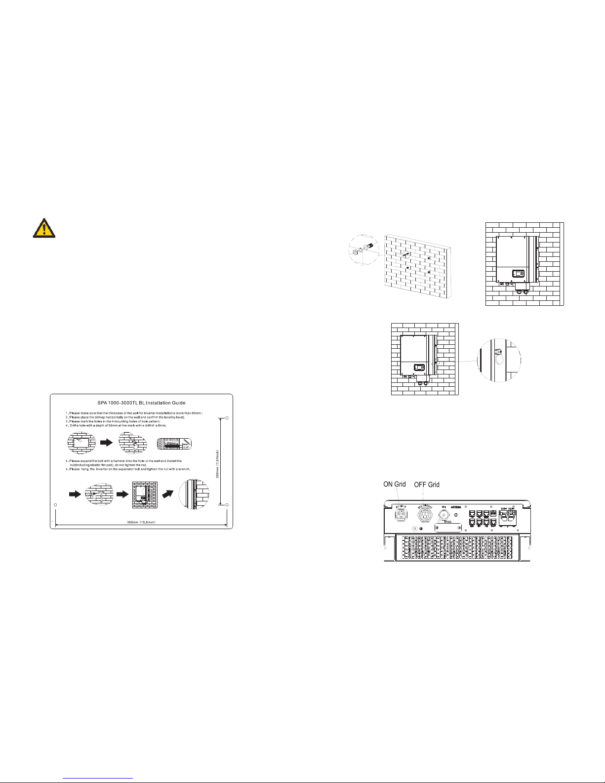
5.3 .2 Inst allat ion of SP A Ser ies
5.4 Sys tem Connection M ode
5.4 .1 Conn ectio n of Grid a nd EPS te rmina l
•
mus t be not le ss than 6 0mm.
•Ma ke s ure the dri ll pos iti on, use pap er boa rd( ins tallation guid e), put the pape r b oard
cli ng to the wal l, make su re the top edg e of paper board is leve l(As th e cha rt 5.8a
bel ow).
•Ma rk f our poi nts at the wall v ia the hol e of the pap er board , the n r emo ve the pap er
boa rd.
•Dr ill fou r Ф8 holes a t the mar k point , the dep th is not l ess tha n 55mm.
•Kn ock fou r explo sion bo lt intoФ8 h oles( As t he ch art 5 .8b b elo w).
•Ha ng the en ergy st orage m achin e on the fo ur sets crews (A s the c har t 5.8 c below) .
•Lo ck the nu t of sets crew( As t he ch art 5 .8d b elow).
•Th e whole i nstal latio n has fin ished .
Pro jec t the mac hin e's pro bab ly size on the wal l; the thic kne ss of wal l for SPA Seri es
SPA has a G rid out put term ina l and EPS out ter min al. Look dow n o n t he S PA f rom the
fro nt, th e te rminal on th e left (AC gri d) i s gr id o utl et for co nnect ing gr id,t he t erm ina l
on th e right i s an emer gency p ower ou tlet fo r conne cting c ritic al load .
Fig 5 .9
a
b c
d
Fig 5 .8
Page 10
14
13
Con ducto r cross
sec tion
Max c able le ngth
SPA 10 00T L BL
SPA 20 00T L BL
SPA 30 00T L BL
5.2 mm^2 10 AWG
60m
50m
30m
3.3 mm^2 12 AWG
40m
30m
20m
The s ugges t lengt h of the wi re
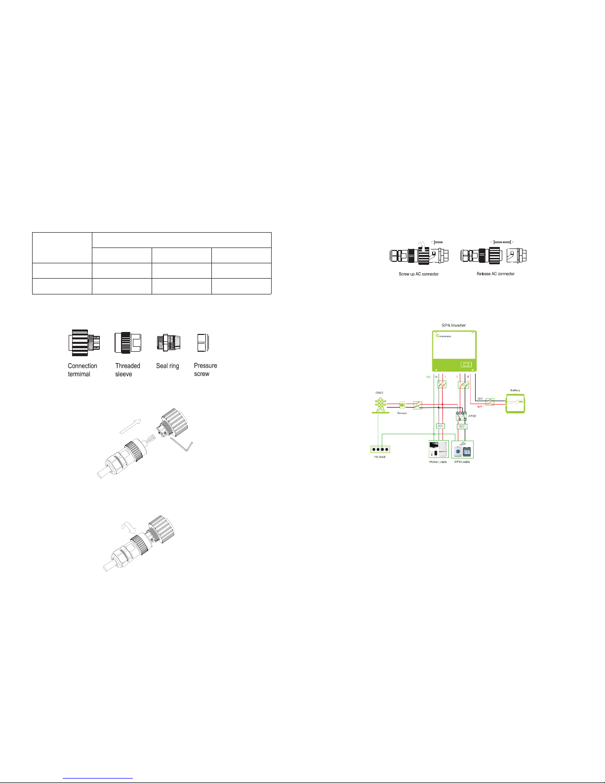
AC ou tput te rmina l conne ction s teps as f ollow :
Ste p 1:Un ins tal l the A C ter min al as a bov e cha rt
Ste p 2:Th rea d cab les t hrou gh pr ess ure screw, s eal r ing , thr eaded sleeve i n seque nce,
ins ert cab les int o conne ction t ermin al acco rding t o pol ari tie s ind ica tes o n it an d tighten
the s crews .
Table 5 .3
Fig 5 .10
Fig 5 .11
Fig 5 .12
Ste p 3:Pu sh th rea ded s lee ve on to connect ion ter minal u ntil bo th are lo cke d tig htl y.
Fig 5 .13
Fig 5 .14
Ste p 4:Pl ug th e soc ket i nto A C out put t erm ina l, cloc kwise r ota tio n to ti ght en th e
soc ket, co unter clo ckw ise rotation t o loose n the soc ket. Th e recom men ded w iri ng
dia gram is a s follo ws:
•
wir ing con necti on.
Thi s di agram is an example for gird sys tem wit hou t spe cia l req uire men t on elec tri cal
Page 11

15
16
Fig 5 .15
Fig 5 .16
•
lin e can't b e switc hed.
Thi s dia gra m is an example for Australi an an d New Z eal and gird sys tem whe re n eut ral
Thi s diagr am is an ex ample f or cust omer wh o only wa nt to use t he on gri d stora ge syst em .
Dec larat ion for E PS load
Ple ase mak e sure th e EPS l oad p owe r is wi thi n the S PA outp ut ra tin g, ot her wis e SPA wi ll
shu tdown w ith an EP S Volt Low w arni ng. T hree t ime s EPS Vo lt Lo w wil l cau se ov erl oad
war ning . EPS f unc tion will be loc ked one h our and o utput p ower ag ain.
•Ac cepte d EPS loa ds, Telev ision , compu ter, fri dge , fan , lamps, micro wav e ove n, el ect ric
ric e cooke r,sm all pow er air co nditi oner an d route rs et c.
•Un accep ted EPS l oads, w ith hig h power t han SPA ou tpu t rat ing a nd hi gh in rus h cur rent
at st art-u p.
NOT ICE:
•
flo at EPS ou tput.
•If you want to u se b oth on g ird p ower and back up power ,please refe r to Fig 5.1 4 an d
5.1 5. conn ect wit h AC grid a nd EPS OU TPUT li ke the ch art sho w.
•AC g rid ter minal a nd EPS te rmina l can't d irect ly co nne ct to get her.
•EP S termi nal can 't conn ect to gr id.
•If you w ant to u se o n gird and o ff grid, yo u ca n us e ATS (Au tom ati c tr ans fer swi tch ) or
EPS Cha nge ove r Sw itc h(M anu al s witch) l ike Fi g 5. 14 a nd 5 .15 before o r as k Gro watt f or
hel p to conn ect the m.
•Th e first s tart of s ystem n eeds th e Grid po wer.
If yo u want to u se on gir d onl y, plea se re fer t o Fig 5 .16 t o con nec t with AC grid and
Ins tall ba ttery s teps ar e as fo llo ws:
•Op en the wa terpr oof c ove r.
•Th read ca ble s thr ough pres sur e scre w, seal ri ng, thr ead ed sl eev e, wa ter proo f cover.
•Th read cable s in to con nec tio n t erm ina l, then press t he ter min al by relev ant tools and
mak e sur e b attery cab les are firm ly (G row att lith ium batte ry co nta ins a ba tte ry c able in
the o rigin al pack ing) .
•Co nnect positive po le (+ ) of ba ttery cable to b att ery p osi tiv e ter min al (+ ) of the i nve rte r,
con nect ne gativ e pole (- ) of batt ery cab le to bat tery ne gativ e termi nal (-) .
5.4 .2 Conn ectio n of batt ery ter minal
a
b
Fig 5 .17
Fig 5 .18
Page 12

17
18
NOT ICE:
NOT ICE:
NOT ICE:
We s ugges t the dis tan ce b etwee n bat ter y an d SPA Ser ies no lo nge r th an 1 .5m, and The
pow er line a rea mus t be la rge r tha n 6 AWG( 13. 3mm ^2) .
5.4 .3 Conn ectio n of CT2 te rmina l
5.4 .4 Conn ectio n of CT1 te rmina l
If the SPA is installed with an exis tin g inv erter, the re is a CT2 to moni tor the inv ert er
cur rent.
The C T2 term inal co nnect ion ste ps are as f oll ows :
•Un screw t he sw ive l nut f rom the cab le glan d.
•Th read th e swi vel n ut ov er th e “CT 2” ca ble .
•Pr ess t he ca ble s upp ort s lee ve ou t of th e cable gland.
•Re move th e fille r plug fr om th e cab le su ppo rt sl eev e.
•Ro ute the “ CT2” ca ble thr oug h an op eni ng in t he ca ble s upp ort sleeve.
•Th read th e “CT 2” ca ble t hrough th e cable g land.
•In sert t he RJ4 5 plug of t he n etw ork cab le i nto the “CT 2” p in connecto r on th e inve rter
unt il it sna ps into p lace.
•If no other cabl es need to b e i nstalled, lock the wat erproof cove r t o t he inv ert er wit h
scr ews .
•Sc rew the s wiv el nu t ont o the w ate rpro of cove r.
Fig 5 .19
Fig 5 .20
•
the c able su pport s leeve .
•Ct 2 wire ( 5m in l eng th) s pec ifi cat ion : RJ4 5, st andar d LAN line (on e end w ith 8 P modu lar
plu g, t he othe r co nnect ed with cur rent tran sfo rme r). But if the leng th is not eno ugh ,
cus tomer can a dd c abl e, s o th e le ngth can be i ncreased t o 15 m ma x, t he o per ati on i s as
fol low Fig :
If the cable such as “C T2” cable is no t use d, p lease do no t remove the filler p lug from
Fig 5 .21
Dur ing the actual operation, plea se pay at tention to the ins tallation of curre nt
tra nsfor mer as th e diagr am show s below :
As illus trate d above, op en th e cur rent t ransf ormer a nd you c an se e an ar row l abe led o n it
ind icati ng t he dire cti on of c urr ent . Put the live wir e amo ng the und er-d ete cti on wires
ont o the c urrent t ran sfo rme r. Aft er l atc hing the cur rent tra nsf orm er, th e in sta lla tio n has
bee n finis hed.
Fig 5 .22
Fig 5 .23
Fig 5 .24
The dire cti on of t he ar row on th e curre nt tr ans for mer i s cor respo ndi ng to t he di rec tio n of
the cur rent in li ve wi re fr om gr id to t he exi sti ng in ver ter. Cu rrent t ran sfo rme r nee ds to be
pla ced in th e power d istri butio n cabin et.
The re is a CT 1 i n S PA s eri es monitoring th e pow er consu mptio n sit uatio n of resid ent ial
use rs, the C T1
ter minal c onnec tion st eps are a s fol low s:
•Un screw t he sw ive l nut f rom the cab le glan d.
•Th read th e swi vel n ut ov er th e “CT 1” ca ble .
•Pr ess t he ca ble s upp ort s lee ve ou t of th e cable gland.
•Re move th e fille r plug fr om th e cab le su ppo rt sl eev e.
•Ro ute the “ CT1” ca ble thr oug h an op eni ng in t he ca ble s upp ort sleeve.
•Th read th e “CT 1” ca ble t hrough th e cable g land.
•In sert t he RJ4 5 plug of t he networ k cabl e into the “CT1” pin conne ctor o n the inve rter
unt il it sna ps into p lace.
•If no other cables need to b e i nst all ed, lock the wat erp roof c over t o t he inv ert er wit h
scr ews .
•Sc rew the s wiv el nu t ont o the w ate rpro of cove r.
Page 13

19
20
NOT ICE:
NOT ICE:
NOT ICE:
•
sel ectin g CT1 or el ectri city me ter, ple ase re fer to se ction 6 .4.4 fo r det ail s.
•If the c abl e s uch as “ CT1” cab le i s not u sed , pl eas e d o no t re mov e th e fil ler plu g f rom
the c able su pport s leeve .
•CT 1 wir e (5m i n len gth ) spe cif ication: RJ45, stand ard LAN l ine ( one e nd wi th 8P
mod ular plug , th e oth er conn ect ed with cur rent tra nsfor mer). But if the leng th is not
eno ugh, cu stome r can a dd ca ble , so th e len gth c an be incre ase d to 15 m max , the
ope ratio n is as fol low Fig :
The mete r a nd CT1 can't be i nst all ed at s ame t ime , p lea se set the sens or mod el when
Dur ing the actua l o per ati on, ple ase pay attention to th e i nst all ati on o f cu rren t
tra nsfor mer as th e diagr am show s below :
Fig 5 .26
Fig 5 .25
As illustra ted ab ove, ope n the c urrent t ransformer and y ou ca n see a n arr ow la bel ed on i t
ind icati ng t he dire cti on of current . Put the liv e wire amo ng the unde r-de tec tio n wire s
ont o the c urr ent t ransf ormer. Afte r latc hin g th e cu rren t tr ans for mer, t he i nst all ation ha s
bee n finis hed.
The d irect ion o f the a rro w on th e cur ren t tra nsf orm er is c orre spond ing to the di rect ion o f
the curre nt in liv e wi re f rom gri d to the l oad . Cu rre nt t ran sfo rme r ne eds to be p lac ed i n
the p ower di strib ution c abine t.
5.4 .5 Conn ectio n of mete r termi nal
We als o c an u se me ter inst ead of C T1 in S PA s eri es to m oni tor the pow er consumptio n
sit uatio n of
res ide nti al us ers , the m ete r ter min al connectio n steps a re as fol low s:
•Re feren ce 5. 2, ma ke LA N cab les w ith R J45 t erm inal.
•Th read th e swi vel n ut ov er th e LAN c abl e.
•Pr ess t he ca ble s upp ort s lee ve ou t of th e cable gland.
•Re move th e fille r plug fr om th e cab le su ppo rt sl eev e.
•Ro ute the L AN cabl e throu gh an o pen ing i n the c abl e sup por t sleeve.
•Th read th e LAN c abl e through the ca ble gla nd.
•In sert th e RJ4 5 plu g of the n etw ork c able into t he “M ete r” pin conn ect or on t he
inv erter u ntil it s naps in to plac e.
•If no othe r cab les need to be i nstal led, lock the waterpr oof cove r t o t he inv ert er wit h
scr ews .
•Sc rew the s wiv el nu t ont o the w ate rpro of cove r.
Fig 5 .27
Fig 5 .28
•
sel ectin g CT or ele ctric ity met er, plea se ref er to sec tion 6. 4.4 for d eta ils .
•Me ter m ust be pr ovi ded by Grow att . I f no t, may be m ete r c an' t co mmu nic ate with SPA
ser ies.
•Th e more de tai l des cri be of m ete r ins tal lat ion, please tu rn to me ter u ser m anual
Met er and C T can 't be ins tal led a t sam e time , ple ase s et th e sen sor model w hen
Page 14

21
22
5.4 .6 Conn ectio n of comm unica tion te rmina l for lit hium ba ttery (RS48 5)
5.4 .7 Conn ectio n of comm unica tion te rmina l for lit hium ba ttery (CAN)
Whe n usin g li thi um b atteries wh ich nee d to connect BMS sys tem of th e batt ery, c onn ect
lit hium ba ttery t ermin al (RJ4 5) step s as foll ows:
•Un screw t he sw ive l nut f rom the cab le glan d.
•Th read th e swi vel n ut ov er th e “RS 485 ” cab le.
•Pr ess t he ca ble s upp ort s lee ve ou t of th e cable gland.
•Re move th e fille r plug fr om th e cab le su ppo rt sl eev e.
•Ro ute the “ RS485 ” cable t hroug h an op eni ng in t he ca ble s upp ort s leeve.
•Th read th e “RS 485 ” cab le th roug h the cab le glan d.
•In sert th e RJ45 plug o f the ne two rk cab le into t he “RS 485 ” pin co nnect or on the
inv erter u ntil it s naps in to plac e.
•If n o othe r cabl es need to be i nst all ed, lo ck the w ate rpro of cover to th e SPA with
scr ews .
•Sc rew the s wiv el nu t ont o the w ate rpro of cove r.
RS 48 5
Fig 5 .29
Fig 5 .30
Fig 5 .31
Fig 5 .32
NOT ICE:
NOT ICE:
•
ple ase ski p this st ep to 5.4 .5.
•Th e CAN bat tery commu nicat ion and R S485 batte ry comm unica tion can't b e installe d at
sam e t ime , ple ase select the cor rec t com mun ica tio n metho d a cco rdin g t o the ba tte ry
man ual.
•If t he cabl e such as “RS485” c able or “CAN ” cable is not used , please do not rem ove t he
fil ler plu g from th e cab le su ppo rt sl eev e.
If y ou are usi ng a le ad- aci d bat ter y, you d o not n eed t o ins tall this c omm uni cation c abl e,
Whe n using CAN communic ation w ith lithium batteries , connect lithium batte ry termina l
(RJ 45) ste ps as fol lows:
•Un screw t he sw ive l nut f rom the cab le glan d.
•Th read th e swi vel n ut ov er th e “CA N” ca ble .
•Pr ess t he ca ble s upp ort s lee ve ou t of th e cable gland.
•Re move th e fille r plug fr om th e cab le su ppo rt sl eev e.
•Ro ute the “ CAN” ca ble thr oug h an op eni ng in t he ca ble s upp ort sleeve.
•Th read th e “CA N” ca ble t hrough th e cable g land.
•In sert t he RJ45 p lug of th e network ca ble into the “CAN” pi n connector on the in ver ter
unt il it sna ps into p lace.
•If no o ther cable s nee d to be in stall ed, l ock t he wa terpr oof cove r t o t he inv ert er wit h
scr ews .
•Sc rew the s wiv el nu t ont o the w ate rpro of cove r.
CAN
If yo u are usi ng a le ad- aci d bat ter y, you do n ot ne ed to i nst all t his c omm uni cation cable.
•Th e CAN battery communi catio n and RS485 batt ery c ommun icati on can't be inst alled
at sam e ti me, ple ase select t he c orr ect com mun ica tio n me tho d ac cor din g to the b att ery
man ual.
•If the cable such as “ RS4 85” cabl e o r “ CAN ” c abl e i s n ot used, p lease do n ot rem ove
the f iller p lug fro m the c abl e sup por t sle eve .
Page 15

5. 4. 8 Con nection of tempe rature probe for l ead-aci d batte ry
5. 4. 9 Con nection of DRMs te rminal( Austral ia only)
Fig 5 .33
Fig 5 .34
Fig 5 .35
Fig 5 .36
23
24
Whe n custo mer usi ng lead -acid b atter y, the t emper ature p rob e of th e lea d-a cid battery is
use d to dete ct the am bient t emperatu re of the l ead -ac id ba tte ry, the b att ery t emp era tur e
cab le of the S PA si de co nnection steps ar e as fo llo ws:
•Un screw t he sw ive l nut f rom the cab le glan d.
•Th read th e swi vel n ut ov er th e “NT C” ca ble .
•Pr ess t he ca ble s upp ort s lee ve ou t of th e cable gland.
•Re move th e fille r plug fr om th e cab le su ppo rt sl eev e.
•Ro ute the “ NTC” ca ble thr oug h a min o pen ing i n the c abl e sup port sleeve.
•Th read th e “NT C” ca ble t hrough th e cable g land.
•In sert t he R J45 plu g of t he net wor k ca ble int o the “NT C” p in c onn ect or on the inv ert er
unt il it sna ps into p lace.
•If n o othe r cabl es need to be i nst all ed, lo ck the w aterpro of cover to th e SPA with
scr ews .
•Sc rew the s wiv el nu t ont o the w ate rpro of cove r.
•
pro be of the temp era tur e c abl e s hou ld be att ached to the surro und ing envi ron men t o f
the l ead -ac id ba ttery, and th e len gth of this c abl e is 1.5 m, so pa y att ent ion t o the
dis tance o f batte ry and SPA s eri es.
•If the cab le such as “NTC ” (le ad- aci d bat ter y tem per atu re sens or) cab le is not use d,
ple ase do no t remov e the f ill er pl ug from the c able su pport s leeve .
If y ou are us ing a lit hiu m bat ter y, you do no t ne ed to ins tal l thi s te mpe rat ure p robe, th e
NOT ICE:
NTC
Whe n SPA series is app lie d to Au str ali a, the DRMS ter min als need to be conn ect ed, the
con necti on way ap pears a s follo ws:
•Un screw t he sw ive l nut f rom the cab le glan d.
•Th read th e swi vel n ut ov er th e “DR MS” c abl e.
•Pr ess t he ca ble s upp ort s lee ve ou t of th e cable gland.
•Re move th e fille r plug fr om th e cab le su ppo rt sl eev e.
•Ro ute the “ DRMS” c able th rough a n ope nin g in th e cab le su ppo rt sl eeve.
•Th read th e “DR MS” c abl e through t he cabl e gland .
•In sert th e RJ4 5 plu g of th e netw ork cab le in to th e “DR MS” pin con necto r on th e
inv erter u ntil it s naps in to plac e.
•If no other cables need to b e i nst all ed, lock the wat erp roof c over t o t he inv ert er wit h
scr ews .
•Sc rew the s wiv el nu t ont o the w ate rpro of cove r.
DRM S
PIN
Ass ignme nt for in verte r scapa ble
of bo th char ging an d disch argin g
PIN
Ass ignme nt for in verte r scapa ble
of bo th char ging an d disch argin g
1
DRM 1/5
2
DRM 2/6
3
DRM 3/7
4
DRM 4/8
5
Ref Gen
6
COM /DRM0
7
/
8
/
RJ 45 t ermin al pin as signm ent:
Table 5 .4
Page 16

25 26
MOD E
RJ 45 s ocket
ass erted b y short ing pin s
Req uirem ent
DRM 056
Ope rate th e disco nnect ion dev ice.
DRM 1
1
5
Do no t consu me powe r.
DRM 2
2
5
Do no t consu me at mor e tha n 50% o f rat ed
pow er.
DRM 335
Do no t consu me at mor e tha n 75% o f rat ed
pow er and so urce re act ive p ower if capabl e.
DRM 4
4
5
Inc rease p owe r con sum pti on( sub jec t to
con strai nts fro m oth er ac tiv e DRM s).
DRM 5
15Do no t gener ate pow er.
DRM 625
Do no t gener ate at mo re than 5 0% of r ate d
pow er.
DRM 735
Do no t gener ate at mo re than 7 5% of r ate d
pow er and si nk reac tiv e pow er if c apa ble .
DRM 8
4
5
Inc rease p owe r gen era tio n (su bje ct to
con strai nts fro m oth er ac tiv e DRM s).
If th e cable s uch as “D RMs” ca ble is no t used, p lease d o not rem ove t he fi lle r plu g from
the c able su pport s leeve .
NOT ICE:
Table 5 .5
Met hod of as serti ng dema nd resp ons e mod es:
5. 4. 10 Gr oundi ng conn ectio n
SPA se rie s mus t be grounded by c able, t he grou ndi ng po int i s sho wed a s fol low, a nd th e
min imum gr oun din g cab le wi re dia meter i s 10AWG (5. 26m m2) .
Fig 5 .37
Page 17

2827
6 Commissioning
6.1 Com missioning of SPA
6.2 Ope ration modes
6.2 .1 Norm al mode
1)E lectr ify SPA se rie s aft er al l ins tal lat ion o f Part5 be finished ,here a re th e ste ps :
Turn o n AC fi rst
•Th en tur n on ba tte ry
•If Gri d an d ba tte ry a re av ail abl e, t he S PA wou ld w ork on the “n ormal ”mo de. Whe n th e
SPA wo rk un der t he no rma l mod e ,th e scre en sh owi ng “n orm al ”a nd th e LED i s green.
2)I f SPA do not enter norm al mod e s ucc ess ful ly, e spe cia lly the L CD is red, you ne ed to
che ck belo w:
•Ma ke sure a ll th e con nec tio n is co rrec t.
•Al l the ext erna l swi tch es are o n.
•Ma ke sure t he li thi um ba tte ry is o n.
•Re fer to Pa rt 9.1 fo r corre cti on.
You ca n ref er t o 6.4 .4 for wo rk mo de s ett ing , the n con figur e monito r,fi nish com mis sio ing l astly.
Nor mal mod e is work ing sta te whic h inclu ding on line mo de and ba ckup mo de.
Onl ine mod e
Use r can se t an appro pri ate p rio rit y mod e acco rdin g to reque st whe n SPA wo rki ng on t he
onl ine
mod e. If cus tom er u se t he L CD and ke y sett ings, you can onl y se t on e period, bu t if yo u
use w ebsit e
set tings , you can set up t o t hree peri ods of the priority mode. Please refer to 6 .4.4 for
det ails.
Loa d first : Load fi rst is th e defau lt mode .
•
op tim ize l oad, t hen c har ge ba tter y,
exc eed pow er expo rt to the g rid.
Wi th inv ert er, e ner gy fro m i nve rte r
•
inv erter is we ak, t he ba tte ry wi ll di schar ge
for loa d fi rst ly a nd t he g rid will suppl y the
pow er w hen t he b att ery p owe r is n ot
eno ugh.
Wi tho ut i nvert er or the en erg y f rom
Bat tery Fi rst: Wh en SPA ser ies w ork ing u nde r thi s mod e, ba ttery would be char ged fir st,
it' s suita ble wor king on t he peri od when t he elec tric ch arge is l ow. User n eed to se t the
mod e ON and OF F time, and the e nd time o f batte ry SOC. U sers ca n set pow er rate w hich
les s than th e batte ry maxi mum out put pow er.
•
cha rge ba tte ry, the n load an d the g rid
wil l su ppl y the pow er when the inverte r
pow er is not e nough .
Wi th in vert er, e nerg y fro m inv erte r
•
inv erter i s weak , the gri d wil l char ge
the b atter y and loa d.
Wi tho ut inve rter or the en ergy fro m
Gri d fi rst : Whe n SPA serie s wo rki ng unde r Gri d-f irs t mode , th e bat ter y ene rgy wou ld
fee d to G rid fir st. Use r ca n ch oos e th e pe rio d wh en e lec tri c ch arg e is hig h. U ser need to
set the m ode ON an d OFF time, an d the end t ime o f batt ery S OC. User can s et power rat e
whi ch less t han the b atter y maxim um outp ut powe r.
•
loa d. If t he sum of inv erter po wer
and bat tery pow er is g rea ter t han t he
loa d, exce ss powe r flows t o the gri d.
Wi th inv erter, batt ery discharge to
•
inv erter is wea k, b att ery discha rge to
loa d and exc ess pow er flow s to the gr id.
Wi tho ut inverter or the en erg y fro m
Fig 6 .1
Fig 6 .2
Fig 6 .5
Fig 6 .6
Fig 6 .3 Fig 6 .4
Page 18

29
30
Bac kup mod e: If t he grid lost ,sy ste m w oul d tur n to bac kup mod e(user can disa ble it
,re fer to 6.4 .4) and AC output is from EPS port . All of the ener gy is f rom batt ery .SPA
max imum o utp ut po wer is SPA n omi nal p owe r in t his m ode, t he lo ad w hich con nec t wit h
EPS p ort sho uld be le ss than S PA no min al power.
•W ith out g rid , battery dischar ge to EPS l oad. SPA w ork u nde r EPS m ode .
NOT ICE:
NOT ICE:
NOT ICE:
For Battery first and Grid first mode, custom er can set th e ti metable for it. Th roug h LC D
can s et one ti me peri od, thr oug h Gro watt ShineSe rver ca n set 3 tim e perio ds each .
The SPA 's intel ligen t cont rol sy ste m co uld mon ito r an d ad jus tme nt s yst em' s status
con tinuo usly, wh en SPA
ser ies mon ito rin g any thi ng unex pected happ en, suc h as syst em faul t or machi ne f aul t
,th e LCD wil l
dis play th e fault i nform ation , in faul t mode, t he red LE D lig ht wi ll be l igh ten .
•
•So me fau lt in for mat ion i s in or der t o rem ind u ser s tha t hav e som e faults occurre d in SPA
sid e.
The d etail 's faul t infor matio n pleas e refer t o 9.1 .
6.2 .2 Faul t mode
6.2 .4 Chec king mo de
6.2 .5 Stan dby mod e
6.2 .6 Shut down mo de
6.2 .3 Prog rammi ng mode
Pro gra mmi ng m ode ind ica te t he S PA i s up dat ing ,do n't cut out power (Grid and B att ery )
whe n it's u pda tin g unt il th e pro ces sin g is finish.S PA in ver ter w oul d log out a uto mat ica lly
whe n the upd ating i s finis hed and t urn to o the r mode .
Bef ore SPA work i n no rma l m ode, it will go t o self-che ck mo de. If all are ok, syste m wil l
go to n ormal m ode ,ot herwi se, it wi ll go to fa ult mod e.
If t he system hasn' t fault while the condi tion is no t qualifi ed, SPA wou ld s tay at s tan dby
mod e.
If u ser need SPA st op w ork ing , us er m ust dis con nec t al l th e en erg y so urce , then SPA wil l
tur n into s hut dow n mode automat icall y.
The f ollow ing is th e shutd own pro ced ure :
•Tur n off b att ery switch.
•Sh ut down A C power. T hen y ou ca n see the both LED a nd LCD ar e off .
Aft er all th e actio ns are do ne, y ou st ill h ave t o wai t for m ore th an 5 mi nut es.
6.3 Cou ntry setting
Gro wat t can provide vario us regul ati ons of th e mach ine , afte r cust omers rece ive th e
mac hine, a cco rdi ng to th eir c oun try, by di aling D IP sw itc h to set t he corres pon din g
reg ula tio ns. F oll owi ng is t he DI P swi tch intro duc tio n.
Fig 6 .7
Fig 6 .8
Page 19

31
32
The DIP s wit ch i s co mpose d of f ive -di git bin ary num ber PINS. The d ifferen t co mbina tion
of the five PINS can repr ese nt diff erent mode l, whi ch is c orres pon din g t o t he loca l gri d
sta ndard . Eac h small whi te PIN has two statu ses, when set upw ard to “ON ”, its value
tur ns t o “ 1”, when set dow nwa rd, its val ue tur ns to “ 0”. Conc ern ing the mat chi ng of
the P IN stat us and th e count ry safe ty stan dard, p lea se re fer to the table b elow:
Cau tion :
Whe n you set ting th e DIP, you mu st turn off AC and b atter y
bre ake r to ma ke su re all of the p ower ar e off .
Cau tion:
1. Af ter set ting th e DIP, plea se power on the SPA seri es an d
che ck the mo del dis play (s how as 6. 3.1). I f the mod el disp lay is
mat ch what y ou want , it mean s your se tting i s succe ssful .
2. You ne ed t o ca lib rat e th e ti me t hat the mac hin e is sho wing
aft er SPA ser ies s tar ts up .
If th e count ry is set i ncorr ect ly, ple ase s hut d own t he
SPA se rie s and s et ag ain
DIP s witch s tatus
Cou ntry/ regio n / reg ula tions
Mod el disp lay
VDE 0 126
GT0 XXXXX X1
Que ensla nd
GT0 XXXXX X2
As4 777
GT0 XXXXX X3
42 31
ON
5
42 31
ON
5
42 31
ON
5
CEI 0 -21
GT0 XXXXX X4
G59
GT0 XXXXX X5
XIN A1
GT0 XXXXX X6
VDE -AR-N 4 105
GT0 XXXXX X7
G83
GT0 XXXXX X8
Nor way-E N5043 8
GT0 XXXXX X9
CQC
GT0 XXXXX XA
Dan mark- EN504 38-1
GT0 XXXXX XB
Hun gary
GT0 XXXXX XC
Bel gium
GT0 XXXXX XD
42 31
ON
5
42 31
ON
5
4
2 31
ON
5
42 31
ON
5
42 31
ON
5
42 31
ON
5
42 31
ON
5
42 31
ON
5
42 31
ON
5
42 31
ON
5
6.3 .1 Swit ch to cou ntry ta ble
Page 20

33
34
Tha iland M EA
GT0 XXXXX XE
Tha iland P EA
GT0 XXXXX XF
Sp1 663
GT1 XXXXX X0
CQC -1
GT1 XXXXX X1
TAIWA N
GT1 XXXXX X2
EN5 0438- Irela nd
GT1 XXXXX X3
TUV 000
GT1 XXXXX X4
42 31
ON
5
42 31
ON
5
42 31
ON
5
42 31
ON
5
42 31
ON
5
42 31
ON
5
42 31
ON
5
6.4 Dis play and button
6.4 .1 LCD di splay a rea
Vb/Cb:50 V/4 0%
Normal
Loc ation
Des cript ion
A
Inf ormat ion
B
Sta te
C
SPA in ver ter
D
Pow er flow l ine
E
Gri d
F
Loc al load
G
Wi rele ss comm unica tion
H
RS 23 2
I
RS 48 5
J
Bat tery (s how the S OC in fiv e grid, E very gr id repr ese nts 2 0%)
K
Buz zer(R eserv ed)
L
War nin gMFau lt
Fig 6 .9
Table 6 .2
Table 6 .1
Page 21

36
35
6.4 .2 LED an d button instru cti on
6.4 .3 LCD di splay c olumn
Loc ation
Des cript ion
A
Sta tus
B
ESC - butto n(can cel con trol)
C
Dow n-but ton
D
Ent er-but ton
E
UP- butto n
Fig 6 .10
Table 6 .3
Table 6 .4
Des cript ion
Exp lanat ion
Pus h-but ton
Ope ratio n of disp lay scr een a nd se t sys tem
Sta tus sym bol
of SPA
Gre en li ght o n
SPA ru n nor mal ly
Red l ight on
Fau lt stat e
Gre en li ght b lin kin g
Ala rm stat e
Red l ight So ftwar e upd ati ng
Sof tware u pda tin g
LCD dis play c olu mn is u sed to show t he cu rre nt st ate , bas ic inf orm ati on an d fau lt
inf ormat ion. Also incl ude lan gua ge set tin g, progr am charg ing/d ischa rging pri ori ty and
sys tem tim e. On def ault co nditi on will t ake tur ns to di spl ay the informatio n.
Vb/ Cb:50 V/40%
Nor mal
Fig 6 .11
Fig 6 .12
The A l ine's c onclu ding in forma tion as f ollow :
• SPA ser ies is i n stan dby s tat e. No error in th is state, b ut for o the r
rea son s, ma ke it i n a wai t sta te.
•No rmal st ate: SPA s eri es is i n nor mal w ork ing s tat e.
•Ch eckin g stat e: SPA s eri es is in se lf- che ck st ate , if there is no e rro r or wa rnin g, SPA w ill
go to n ormal s tate or s tandb y state . Other wise it w ill go to f ault st ate.
•Pr ogram ming st ate: SPA i s in up dat ing f irm ware s tate.
•Fa ult state :SPA has fa ult in forma tion, it will be in st opp ed ope rat ional prot ect ion
sta te.
The B line's informat ion as follow: In norm al, it will tur n on page aut oma tic all y, w hen
pus hing th e butto n
“UP” , the ord er of t he pa gin g inf orm ati on as f ollow:
Sta ndby st ate :
WorkMode
Input&Output Para
WorkMode
(Lead acid)Vb:xx.xV
(Lithium)Vb/Cb:xx.xV/x
xx%
Battery info
WorkMode
Pbat: (+/-)XXXX W
Battery power
WorkMode
Grid:xxxV/xxHz
Grid
WorkMode
Po:xxxxW/xxxxVA
Output AC Power
WorkMode
EPS:xxxV/xxHz
EPS
WorkMode
EPS:xxxxW/xxxxVA
EPS
WorkMode
PL: xxxxW
Load AC Power
WorkMode
Pex: xxxxW
Extra AC Power to grid
WorkMode
Pm: (+/-)XXXXW
MasterPower
WorkMode
Ec_d:xxxx.x KWh
BAT Charge_Etoday
WorkMode
Ec_a:xxxx.x KWh
BAT Charge_Etotal
WorkMode
Eac_d:xxxx.x KWh
AC output_Etoday
WorkMode
Eac_a:xxxx.x KWh
AC output_Etotal
WorkMode
Eld_d:xxxx.x KWh
Load_Etoday
WorkMode
Eld_a:xxxx.x KWh
Load_Etotal
WorkMode
EPS_Load: %
EPS
WorkMode
Ed_d:xxxx.x KWh
BAT Discharge_Etoday
WorkMode
Ed_a:xxxx.x KWh
BAT Discharge_Etotal
WorkMode
Etg_d:xxxx.x KWh
ToGrid_Etoday
WorkMode
Etg_a:xxxx.x KWh
ToGrid_Etotal
WorkMode
Etu_d:xxxx.x KWh
ToUser_Etoday
WorkMode
SerNo:xxxxxxxxxx
WorkMode
20XX/XX/XX/ XX:XX
System Time
WorkMode
Model:xxxxxxxxxx
WorkMode
FW Version:xxxx
WorkMode
Etu_a:xxxx.x KWh
ToUser_Etotal
WorkMode
Eex_d:xxxx.x KWh
WorkMode
Eex_a:xxxx.x KWh
Extra AC_Etoday
Extra AC_Etotal
Battery info
WorkMode
(Lead acid)Vb:xx.xV
(Lithium)Vb/Cb:xx.xV/
xxx%
Page 22

37
38
6.4 .4 Work m ode s et up
•”
•Wo rkm ode depen d on t he situation. If SPA is in nor mal state, i t wi ll show ”n orm al” . If
SPA is s tan dby s tat e, it w ill s how a s “st andby” etc.
•So me speci al defin ition s are expl ain ed, for exa mpl e: Vb mea ns the volt age of b att ery.
Cb m ean s the capacit y of lit hiu m battery (o nly l ith ium batt ery sh ow th is data). Pm m ean s
the m onito r power o f user.
Dow n” cont rol com man d (if p ush ing “ up” b utt on, c ommand will go back ).
NOT ICE:
Som e speci al defi nitio ns:
Par amete r:Des cript ion
Vb: Batte ry volt age
Cb: Batte ry capa city (o nly for l ithiu m batte ry)
Pm: Power m onito ring (f rom gri d is po sit ive , to gr id is n ega tiv e )
Kee p press ing “ ent er ”f or 3S ,you can ente r set up su rface ,in th e set u p sur fac e you
nee d hold bu tton.
Ent er or ESC 1 S for sel ectio n, you ca n see the s urfac e as show ing bel ow.
Fig 6 .13
If you choo se CEI and use d SPA inv ert er in I tal y, S PA i nvert er h ave Aut o Tes t fu nct ion .
How t o use the A uto tes t funct ion. Pl ease se e the ann ex.
•Un der the B asic Pa ra ,you c an see th e setup o ption s below a fter pr ess ing E nte r for 1 S:
Fig 6 .14
Fig 6 .15
In the basic Param eter, yo u can set la ngu age ( Eng lis h, Italian ,German), sys tem
tim e , le ad- aci d ce ll c hargi ng vo lta ge ( def aul t is 58V ), dis cha rge low vol tag e (defa ult i s
48V )and le ad-ac id cons tant cu rrent ( def aul t is 60 A).
Und er the Ba ck Up ,yo u can see t he setu p optio ns belo w after p ressi ng En ter f or 1S :
In th e bac k up you c an se t EPS ,i ncl udi ng en abl e or dis abl e (de fau lt is en abl e ),A C
vol tage( defau lt is 230 V) and fr equ enc y(d efa ult s ite 5 0HZ ).
Und er the Pr iorit y ,you ca n see the s etup op tions b elow af ter pre ssi ng En ter :
Basic Parameter
WorkMode
WorkMode
Configuration
WorkMode
MODE Change
WorkMode
Default Set
WorkMode
Priority
WorkMode
BackUp
Press “enter” key more
than 3 seconds into setup
mode
Press “down”
key to the next
item
Press “enter” key
more than 1 seconds to
make sure
Default Set
WorkMode
Auto Test
WorkMode
WorkMode
WorkMode
Language
WorkMode
English
Italian
German
WorkMode
System time
WorkMode
xxD/xxM/xxxxY
WorkMode
Lead-acid CV
WorkMode
58.0 V
WorkMode
Lead-acid CC
WorkMode
60 A
Press “enter” key more
than 1 seconds to make
sure
Press “down”
key to the next
item
Press “enter” key
more than 1 seconds to
make sure
Range from 57.6 to 59.2V,
and the accuracy is 0.1V
Range from 0 to 66A,
and the accuracy is 1A
Basic Parameter
Only display when
battery type is
lead-acid
Only display when
battery type is lead-
acid
WorkMode
Lead-acid LV
WorkMode
48V
Range from 44 to 50V,
and the accuracy is 1V
Only display when
battery type is
lead-acid
WorkMode
BackUp
WorkMode
WorkMode
WorkMode
Backup: Enable
Disable
ACVolt: 230V
240
208
WorkMode
AC Freq: 50 Hz
60
Press “enter” key
more than 1 seconds to
make sure
Press “down”
key to the next item
Press “enter” key
more
than 1 seconds to make
sure
EPS setup
Page 23

39
40
Fig 6 .16
Fig 6 .17
Fig 6 .18
Fig 6 .19
•
dif fer ent p ower, cust ome r nee d to ch eck t he max power of ba ttery.
•T ime se tti ng is 24 -ho ur. If th e end ti me is le ss tha n beg inn ing ti me, i t defa ult s to
spa nning d ays.
Und er the MO DE Chan ge ,you c an see th e setup o ption s below a fter pr ess ing E nte r:
” Powe r Rat e” is used to set up powe r o f bat ter y. So diff eren t batt ery may has th e
NOT ICE:
NOT ICE:
The MODE change has two opti ons whi ch are sens or and batt ery typ es. In the sens or
typ es, yo u can choose c abl e CT( de fau lt) ,m eter a nd SP -CT (w irel ess RF t ran sfe r) .In
the b atter y types ,you c an ch ose l ith ium b att ery o r lea d-a cid b att ery.
Und er the de fault s et ,you c an see th e setup o ption s below a fter pr ess ing E nte r:
Def ault se t is “res ume t o def aul t set tin g ”,p lea se don't use it unles s it's ne cessa ry.
Use r can upg rade in verte r's fir mware v ia th e USB p ort u se a U- dis k.
Ple ase c ont act Growa tt service supp ort to ge t the u pgr ade files, a nd extr act i nto the U dis k.
•Wa rni ng: D on't m odi fy th e folder nam e or p rogr am f ile n ame , it m ay ca use the u pgr ade
fai led.
•Un screw the wat erp roo f li d an d in ser t U- dis k in to t he U SB p ort, the upgrade will beg in
aut omati cally.
•Th e LC D w ill s how “ Pro gra mmi ng” during upgrad e, a fte r f ini she d, it w ill s how
“Pr ogr am O K”, and i nvert er wil l ba ck t o normal wor kin g st ate . Th en pu ll out the U-d isk ,
and s crew th e wat erp roof lid.
6.5 Com munication
6.5 .1 U-di sk Firm ware up grade
USB i s only us ed for fi rmwar e upd ate . Cus tom er ca n't u se it f or charging.
WorkMode
Stop SOC: 100%
Stop SOC: 5%
WorkMode
Time
WorkMode
Power Rate: 100 %
Power Rate: 100 %
Priority
WorkMode
WorkMode
Opt: Load First (default)
Bat First
Grid First
WorkMode
WorkMode
WorkMode
00:00 – 00:00
WorkMode
Save :OK
NO
WorkMode
Time
WorkMode
00:00 – 00:00
WorkMode
Save :OK
NO
If battery first is
choosen
WorkMode
Bat First: ON
OFF
Range from 5 to 100%,
and the accuracy is 1%
Range from 10 to 100%,
and the accuracy is 1%
WorkMode
If Grid first is choosen
Grid First: ON
OFF
Range from 5 to 100%,
and the accuracy is 1%
Range from 10 to 100%,
and the accuracy is 1%
Press “down”
key to the next item
Press “down”
key to the next item
Choose “ON”
to the next item
Choose “ON”
to the next item
WorkMode
Time
WorkMode
00:00 – 00:00
WorkMode
Save :OK
NO
WorkMode
If Load first is choosen
Discharge: ON
OFF
Press “down”
key to the next item
Choose “OFF”
to the next item
MODE Change
WorkMode
Sensor
WorkMode
Cable CT
WorkMode
Meter
SP-CT
Battery Type
WorkMode
Lithium
WorkMode
Lead-acid
Press “enter”
key to make sure
Press “down”
key to the next
item
Press
“enter” key
to make sure
Default Set
WorkMode
WorkMode
YES
Press “enter”
key to make sure
Press “enter” key more
than 3 seconds to make sure
Page 24

41
42
For loc al control, use r can use USB t o RS 232 c abl e co nne ct th e inve rte r to c omp ute r, and
run s oftwa re
Shi neBus , to do par amete rs chec king an d setti ng, do fi rmwar e upg rad e and s o on.
Ple ase c ont act Gro watt su ppo rt f or S hineB us so ftw are. Abou t Sh ine Bus sof twa re, whe n
you n eeded ,
ple ase dow nload f rom off ici al we bsite of Growa tt.
Fig 6 .20
Fig 6 .21
Fig 6 .22
6.5 .2 Use of R S232 po rt
6.5 .3 The SP A’s mon ito rin g
The w iring d iagra m is as fol lows:
Com puter
RS2 32-US B cable
The S PA pro vide RS 232 int erfac e. User s can mon itor th e SPA thro ugh t he following
com munic ation s oluti on.
WiF i conne ction ( optio nal)
Wi Fi co nne cti on steps:
•Re move th e RS232 p ort cov er, turn t he sm all D IP sw itc h Pin 1 and P in2 t o ON.
•Pl ug WiF i-S m odu le in to the RS232 port, an d confi gure th e con nec tio n bet wee n WiF i
mod ule and r out er.
•Cr eat e a use r acc oun t onl ine .
•Pl ease ch eck the S hineW iFi- S man ual f or de tails.
RF co nnect ion (op tiona l)
RF co nnect ion ste ps:
•Re move th e RS232 p ort cov er, turn t he sm all D IP sw itc h Pin 1 and P in2 t o ON.
•Pl ug RF mod ule int o the RS2 32 port , conne ct the La nbox to R outer.
•Cr eat e a use r acc oun t onl ine .
•Pl ease ch eck the S hineL ink man ual for d etail s.
Thi s kind of mon ito rin g ca n on ly b e us ed b y th e mo nitor of Gro wat t's Shi nes erv er / shi ne
pho ne pro vided by th e co mpa ny. T hrough RS2 32 i nte rfa ce c onn ect to Wi- Fi- S/s hin eli nk,
use c omput er term inal/ or mobi le phon e for dat a monit oring .
NOT ICE:
Page 25

43
44
7 Start-up and shut down SPA system
Attention of the installation 8
Use rs can st art-u p SPA inve rte rs th rough follow ing ste ps:
•Tur n the s wit ch on i n tur n of Gr id an d bat ter y.
•Wh en t he LED tur ns green, the working informatio n on LCD indicat es the success ful
sta rt-up o f SPA seri es.
•
•Wa iti ng un til LED and LCD di splay h ave gon e out, th e SPA is shu t dow n com ple tel y.
Turn t he sw itc h off in tur n of Gr id an d bat tery.
7.1 S tart- up the SP A sys tem
7.2 D iscon nect th e SPA sys tem
Hea t di ssi pat ion p erf orm anc e i s ver y imp ort ant w hen S PA se rie s w ork u nde r the
env ironm ent of high tem perature.B ett er heat dissip ation ca n redu ce the pos sib ili ty of
SPA ser ies stop s working. The SPA ser ies is f anl ess and bel ong s t o natural coo ling. The
hot air on the top of the r adi ato r i s ma tch ed wit h the b att ery. The envi ronm ent i s I P65 .
Ple ase p ay att ent ion to t he t emper ature of t he installation env iro nme nt, to ensur e t hat
the b atter y's saf ety and t he norm al work o f the mac hine.
Whe n use bat tery, pl eas e pay a ttention to th e follo w infor matio n:
Cau tion: D o not dis pose of b atter ies in a fi re. The b att eri es ma y exp lod e.
Cau tion: Do not open or dam age batt eri es. Rel eas ed elect rolyt e is har mfu l to the ski n
and e yes.
It ma y be toxi c.
Cau tion: A b att ery can pre sen t a risk of ele ctr ica l s hoc k a nd hig h s hort- circu it cur ren t.
The f ollow ing pre cau tio ns sh oul d be ob ser ved w hen working on batt eries :
•Re move wa tches , rings o r other m etal ob jects .
•Us e tools w ith ins ulate d handl es.
•We ar ru bbe r glo ves a nd bo ots .
•Do n ot lay to ols or me tal par ts on top o f batte ries.
•Di sconn ect cha rging s ource p rio r to co nne cti ng or d isc onn ecting battery te rmina ls.
•De termi ne if b att ery i s inad ver ten tly gro und ed. If i nad ver ten tly g rou nde d, re mov e
sou rce fr om g roun d. Contact with any part of a g roun ded bat ter y ca n re sul t in ele ctr ica l
sho ck. T he l ike lih ood of su ch s hoc k ca n be r edu ced if such grounds are removed duri ng
ins talla tion and main ten ance (a ppl ica ble to eq uip men t a nd r emo te bat tery su ppl ies not
hav ing a gro und ed su ppl y circuit ).
If S PA ser ies doesn't wor k for ove rhe ati ng or too c old , so lve i t ac cord ing to th e fo llo wing
met hods:
•Co nfirm whe ther the r adi ato r air d uct in sta lla tion is re aso nab le, c hoo se th e app rop ria te
pos ition b efore i nst all ati on.
•If le ad- aci d ba tte rie s ar e co nne cte d, c onf irm ing th e NT C of ba tte ry i s in a g ood
ins talla tion.
•Co nfirm whet her the battery tem per atu re i s to o high, too h igh temp era ture of ba tte ry
can als o l ead to S PA f ail to w ork , a t th is poi nt, to v ent ila tio n, coo lin g o r h and le to t he
bat tery.
•If tempe ratur e is low, als o can ap pear the bat ter y low tem per atu re prot ect ion . The
bat tery wil l s tar t with sma ll loa d in lo w t emp era ture ou tpu t. Aft er tempera ture bac k to
nor mal sys tem can w ork nor mally. P lea se be p atient at this t ime.
•If th e temperatu re is t oo lo w, it is pos sible th at batte ry wil l be low te mpe rat ure
pro tec tio n, a t th is t ime , pl eas e pa y at ten tio n to the wor kin g te mpe rat ure rang e listed in
the s pecif icati ons of th e book.
•Se rvici ng of batt eri es sho uld be pe rform ed or sup erv ise d by pe rso nne l k now led gea ble
abo ut batt eries a nd the re qui red p reca uti ons .
•Wh en repl aci ng batte ries, rep lac e wit h the sam e typ e and num ber o f bat ter ies o r
bat tery pa cks.
•Ge neral i nstru ction s regar din g remo val a nd in sta lla tio n of ba tte rie s.
Rem ark: A ll of a bov e action sho uld b e ope rat ed by prof ess ion al pe rson, if yo u wan t to d o
the se work s, you mu st make s ure the w hol e sys tem a re off .
Page 26

45
46
9 Trouble shooting
Our products a re rig orously tes ted be fore productio n. If y ou h ave diffic ult y in the
ins talla tion pr oce ss,
ple ase vis it www.g inver ter.co m to vi ew th e Q&A plan.
Whe n SPA in verte r fau lt h app ens , pl eas e in for m ou r co mpa ny, an d to p rovi de SPA s eries
rel ate d
inf ormat ion, we w ill hav e a profe ssi ona l aft er-s ale s ser vic e per sonnel to answ er you.
Wha t you nee d to prov ide t he in for mat ion a bou t the S PA seri es in clu din g :
•Se rial nu mber
•Mo del
•In forma tion ab out the L CD disp lay
•Br ief des cript ion of pr obl ems
•Th e grid vo ltage a nd freq uen cy
•Ca n you ret ell t he fa ilu re pro ble m? If y ou ca n, wh at ki nd of a s itu ati on
•Di d the pro ble m hap pen i n the p ast ?
•Wh en did th is faul t happe n? Firs t insta llati on?
Abo ut the ba ttery :
•Th e manuf actur er na me an d mod el of b att ery.
•Se rial nu mber
•Ca pacit y of batt ery.
•Th e time yo u buy bat tery an d frequ enc y you u se it .
9.1 Sys tem fault inform ation l ist and t roubl e shootin g sugge stion s
War nin g mes sag e
Err or me ssa ge
Des cript ion
Sug gesti on
War nin g40 1
SP- CT/Me ter
Com munic ation f ault.
1.M ake sur e the w ire b etween
met er and in verte r conne ct well .
2.M ake sur e the d ist anc e of SP -CT
and i nvert er is in th e range o f
spe cific ation .
Res tart in verte r and SP- CT,reco nnect .
War nin g50 6
Bat tery te mpera ture ou t of
spe cifie d range f or char ging
or di schar ging.
Mak e sure th e env iro nment
tem perat ure of ba tte ry is i n the
ran ge of spe cific ation .
AC V Ou trang e
Gri d volta ge faul t.
Ple ase ref er to t he lo cal g rid
sta ndard f or mo re de tails of
the g rid vol tage.
1.M ake sur e AC vo lta ge is i n the
ran ge of loc al stan dard.
2.M ake sur e the A C cab le is w ell
con necte d.
AC F Ou trang e
Gri d frequ enc y fau lt.
Ple ase ref er to t he lo cal
gri d stand ard for m ore
det ails fo r the gri d
fre que ncy.
1.M ake sur e the f req uency is in the
ran ge of loc al stan dard.
2.R estar t inver ter.
Pl ea se c ont act Gr ow att se rv ice
cen ter if re sta rt no t wor k
Pai ringT imeO ut
Com munic ation f ault
1.M ake sur e the d ist anc e of SP -CT
and i nvert er is in th e range o f
spe cific ation .
2 .R es ta rt i nv er te r an d S P- CT,
rec onn ect .
CT LN R evers ed
LN Re verse d
1.M ake sur e the L l ine a nd N li ne of
SP- CT is not r eve rse d.
2.M ake sure the PE of SP- CT is well
con necte d.
BMS C OM Faul t
Com munic ation f ault
1.C heck th e lithi um Batt ery is op en
or no t.
2.C heck t he co nne cti on of lit hiu m
Bat tery and SPA ser ies is go od o r
not .
Bat tery re ver sed
Bat tery te rmina ls reve rse d
Mak e sure th e pos iti ve an d neg ati ve
of ba ttery i s not rev ers ed.
BAT NT C Ope n
NTC o pen
(on ly for le ad-ac id batt ery)
Mak e sure th e tem per atu re pro be of
lea d-aci d batte ry is wel l insta lled.
Bat tery Op en
Bat tery te rmina l open
(on ly for li thium b atter y
1.M ake sur e the b att ery i s wel l
con necte d.
2.M ake sur e bat ter y swi tch i s tur ned
on.
3.M ake s ure th e br eak er b etw een
the b atter y and inv erter i s on.
Ove r Load
E PS o u t p u t o v er l o a d
war ning .
Thr ee tim es EPS Vol t Low
w i l l c a u s e o v e r l o a d
war ning . Off- grid fu nctio n
wil l be lock ed one ho ur
and o utput p ower ag ain.
Pl eas e r ed uce t he lo ad of E PS
out put.
Page 27

47
48
No AC C onnec tion
No Ut ility
1.P lease c onfir m grid is l ost or no t.
2.M ake sur e the g rid c onn ect ion w ell .
3.M ake su re th e breakers o n gr id si de
are o n
Out put Hig h DCI
Out put DC cu rrent t oo
hig h.
Ple ase ref er to t he lo cal
gri d stand ard for
dis conne ction t ime
whe n the out put DC
cur rent is t oo hi gh.
1.R estar t SPA seri es.
2. Ple as e co ntact Gro wat t se rv ic e
ce nt er i f restart c an' t so lv e th e
pro ble m.
Bat Vo ltage H igh
Bat tery Vol tage hi gher
tha n 60V.
1.M ake sur e the b att ery v olt age i s in
the r ange of s pecif icati on or not .
2.M ake su re th e bat ter y con nec tio n is
wel l
3.C heck i f ba tte ry i s really hig her
th an 6 0V. pl eas e disco nne ct t he
co nnect io n of ba ttery a nd ch eck
inv erter.
Bat Vo ltage L ow
Bat tery Vol tage Lo wer
tha n 42 V
1.C heck th e real vo lta ge of b att ery.
2. Ma ke s ur e th e w ir e be tw ee n
bat tery an d inver ter wel l conne cted.
BMS W arn ing :XX X
BMS r epo rt wa rni ng
1.C heck th e warn ing i nfo rmation
fro m lit hiu m bat ter y use r man ual .
2. Ple as e co ntact Gro wat t se rv ic e
ce nt er i f restart c an' t so lv e th e
pro ble m.
BMS E rror: XXX
BMS r epo rt er ror
1. Che ck the w ar nin g i nfo rmat ion
fro m lit hiu m bat ter y use r man ual .
2. Pl eas e c ont act Growa tt servic e
ce nt er i f restart c an' t so lv e th e
pro ble m.
EPS Vo lt Low
EPS o utput v oltag e low
1.C heck th e load of E PS. If ov erloa d
occ urred a t the s ame t ime , reduce
EPS l oad.
2. Re start i nvert er agai n.
Err or me ssa ge
Err or me ssa ge
Des cript ion
Sug gesti on
Err or 41 1
I n t e r n al c om mu n i c a tio n
fai led
1.R estar t SPA seri es.
2.P lease contac t Growatt s erv ice
cen ter if restar t can't so lve t he
pro ble m.
Err or 41 7
Sam ple fau lt
1.R estar t SPA seri es.
2.P lease contac t Growatt s erv ice
cen ter if restar t can't so lve t he
pro ble m.
Err or 41 8
D SP a nd C OM fi rm wa re
ver sion
unm atch, s ystem f ault.
1.R ead DSP a nd COM fi rmwar e
ver sion fr om LC D or sh ine bus .
2.C heck if t he firm ware is c orr ect .
Err or 30 3
Inv erter L N r eve rse d or
gro und
fai led
1.M ake sur e the L l ine a nd N li ne is
not r eve rse d.
2 .M ak e su re t he P E is w el l
con necte d.
Err or 40 5
Rel ay faul t
1.R estar t SPA seri es.
2.P lease contac t Growatt s erv ice
cen ter if restar t can't so lve t he
pro ble m.
Err or 40 7
Aut otest f ailed (only i n Italy )
1.R estar t SPA seri es.
2.P lease contac t Growatt s erv ice
cen ter if restar t can't so lve t he
pro ble m.
OP Sh ort Fau lt
EPS O utput S hort Fa ult
1.C heck th e load of E PS.
2.C he ck t he o ut pu t of EP S.
Esp ecial n ot conn ect to Gr id.
NTC O pen
Int erna l NTC f aul t
Pl eas e con tac t Gro wat t ser vice
cen ter.
Err or 40 6
Mod el set up n ot meet w ith
cer tific ation
Ple ase che ck mo del s et or ch eck
the D IP sett ing.
Err or 40 8
Tempe ratur e ove r ran ge
Ple ase c hec k th e te mpe rat ure is i n
the r ange of s pecif icati on or not .
Table 9 .1
Page 28

49
50
10 EU Declaration of Conformity Warranty 11
Wi th th e sco pe of E U dire cti ves :
201 4/35/ EU Low Vol tage Di recti ve (LVD )
201 4/30/ EU Elec troma gne tic C omp ati bil ity D irec tiv e (EM C)
201 1/65/ EU RoHS D irect ive a nd it s ame ndm ent ( EU) 201 5/863
She nzhen Grow att New E ner gy Techn olo gy Co. Ltd conf irm s t hat the G row att inver ters
and acc ess ori es d esc ribed in thi s do cum ent a re i n com plian ce wit h th e above m ent ion ed
EU di re cti ve s. T he ent ir e E U D ec la ra tion o f C onfo rm ity ca n be fo und a t
www. ginve rter.c om.
•
•
•
The fact ory w arran ty ca rd is encl ose d w ith the pac kag e, ple ase keep the warranty c ard
wel l, warra nty card can be download at , when user need warr ant y
ser vice duri ng the warr ant y per iod , the user mus t pro vid e a c opy of invo ice , war ran ty
car d, an d ens ure the namepl ate of th e inver ter is le gible .
Oth erwis e, Grow att h as th e rig ht to refus e to prov ide t he wa rra nty s erv ice .
www. ginve rter.c om
Page 29

51
52
12 Decommissioning
•
•Wa iti ng un til LED and LCD di splay h ave gon e out, th e SPA is shu t dow n com ple tel y.
Turn t he sw itc h off in tur n of Gr id an d bat tery.
Wat ch ou t the S PA's sh ell h eat a nd pr eve nt to s cald.
Wai t 20 mi nut es until the SPA co oli ng an d the n to di sas sem bly !
•
•Un screw the rad iator an d wa ll- mou nte d anchor scr ew an d th en ta ke d own t he
mac hine fr om wa ll.
Uns crew al l the c onn ect ing c abl e.
12.1 Di smantling the en ergy st orage
12.2 Pa cking the S PA inverter
12.3 St oring SPA in verter
12.4 Di sposing of the SPA inverter
Usu ally pla ced SPA inve rte r in the pac kin g box wit h tape sealin g, If the SPA inve rte r
can not reocc upy, You can cho ose a c hea p car ton for pac kag ing . Car ton req uir ements
mus t mee t the si ze of th e inv ert er and c an suppor t ene rgy storage ma chi ne overall
wei ght.
Sto re SPA seri es in a d ry place where ambi ent tempera tures are alw ays betw een -25° C
and + 60°C.
Do n ot dis pose of SPA inv ert er t oge the r wi th h ous eho ld w aste. Please
acc ordan ce with the dis pos al regulations for ele ctron ic wast e whi ch
app ly at the i nstal latio n site at t hat tim e.
Ens ure that the old uni t a nd, whe re appl ica ble , any access ories are
dis posed o f in a prop er ma nne r.
Product specification 13
13.1 SPA ser ies energ y stroage machin e produ ct specif ication
SPA 1 000 TL
BL
SPA 2 000 TL
BL
SPA 3 000 TL
BL
Out put Dat a(AC)
AC no minal p ower
100 0W
200 0W
300 0W
Max . AC appa rent po wer
100 0VA
200 0VA
300 0VA
Nom inal AC v oltag e (rang e)
230 V (180V- 270V)
AC gr id freq uen cy (r ang e)
50H z / 60Hz (± 5Hz)
Max o utput c urren t
6A
10A
16A
Pow er fact or(@n omina l power )
1
Adj ustab le powe r facto r
0.8 leadi ng…0. 8 laggi ng
THD i(nom inal po wer)
<3%
AC co nnect ion
Sin gle pha se
Inp ut Data (AC)
AC no minal
100 0W
200 0W
300 0W
Max . AC appa rent po wer
100 0VA
200 0VA
300 0VA
Nom inal AC v oltag e (rang e)
230 V (180V- 270V)
AC gr id freq uen cy (r ang e)
50H z / 60Hz (± 5Hz)
Max i nput cu rrent
6A
10A
16A
Pow er fact or(@n omina l power )
1
Adj ustab le powe r facto r
0.8 leadi ng…0. 8 laggi ng
Mod el
Spe cific tion
Page 30

53
54
Sta nd-al one Dat a (AC )
AC no minal o utput p ower
100 0W
200 0W
300 0W
Max . AC appa rent po wer
100 0VA
200 0VA
300 0VA
Nom inal AC v oltag e
230 Vac
Nom inal AC f reque ncy
50H z / 60Hz
Max . outpu t curre nt
6A
10A
16A
THD v(Lin ear Loa d)
<3%
Swi tch tim e
<0. 5s
Bat tery Da ta (DC )
Bat tery vo ltage r ange
42~ 59V
Rec ommen ded bat tery vo ltage
48V
Max c hargi ng and di schar ging cu rrent
24A
Con tinou s charg ing and d ischa rging c urren t
24A
Type of b atter y
Lit hium / Le ad-ac id
Cap acity o f batte ry
2.4 ~19.2 kWh
Eff ici enc y
Max . Charg e effic ien cy
92. 0%
92. 5%
93. 0%
Max . Disch arge ef fic ien cy
92. 5%
93. 0%
93. 5%
Pro tecti on Devi ces
BAT re ver se pro tecti on
yes
AC su rge pro tec tio n
yes
AC sh ort-c ircui t pro tec tion
yes
Gro und f aul t mon ito rin g
yes
Gri d monit oring
yes
Ant i-isl andin g prote cti on
yes
Gen eral Da ta
Dim ensio ns (W / H / D) in m m
428 *474* 178
Wei ght
18. 6kg
Ope ratin g tempe ratur e ran ge
–25° C ...+6 0°C wit h derat ing abo ve 45°C
Noi se emis sion (t ypica l)
≤ 25 dB (A)
Alt itude
200 0m
Sel f-Con sumpt ion(s tandb y)
< 4 W
Topol ogy
HF tr ansfo rmer
Coo ling
Nat ural
Pro tec tio n deg ree
Ip6 5
Rel ative h umidi ty
100 %
AC co nnect ion
Con necto r
BAT co nne cti on
Scr ew
BAT co nne cti on
Scr ew
Int erfac es
Dis play
LCD
Rs4 85/ USB / CAN
yes / yes /ye s
RF/ Wi-F i/G PRS /
opt /opt/ opt/
War ran ty: 5 y ears / 10 years
yes / opt
Page 31

55
56
Cer tific ates an d appro vals
Gri d regul ati on
CEI 0-21, G83/2 ,G100 ,AS/N ZS477 7.2,V DE-AR -N410 5,VDE 012
6-1 -1,EN 50438 ,TR3. 3.1,I EC621 16,IE C6172 7,UTE C 15-71 2
EMC
EN6 1000- 6-1,E N6100 0-6-3
Saf ety
IEC 62477 -1, IEC 6 2040- 1
Upp er cove r screw s
1.3 Nm(10 .8 1bf. in)
She ll and RS 232sc rews
0.7 Nm(6. 2 1bf.i n)
DC co nnect or
1.8 Nm(16 .0 1bf. in)
M6 sc rewdr ive r
2Nm (18 1bf .in)
Gro und ing s crew
2Nm (18 1bf .in)
Nam e
Des cript ion
Gro watt P/ N
Shi ne link
Use d for dat a recor d in EU
MR0 0.000 7200
Use d for dat a recor d in Au str alia
MR0 0.000 6100
Shi ne Wi- Fi- S
COM i nterf ace
MR0 0.000 8600
GRR S
COM i nterf ace
MR0 0.000 9601
SP- CT
Wi rele ss mete r senso r
MR0 0.000 6500
SPM (Sing le phas e meter )
Rs4 85 mete r senso r of East ron
MR0 0.000 8800
13.2 Tor que
13.3 Ap pendix
SPM (Sing le phas e meter )
Rs4 85 mete r senso r of CHNT
MR0 0.001 0800
TPM (thre e pha se me ter )
Rs4 85 mete r senso r (stan dard)
MR0 0.000 8300
Rs4 85 mete r senso r (for It aly)
MR0 0.000 8400
EPS C hange over Sw itch
On- Gird an d Off -Gr id transfer sw itch
TV0 3.000 1200
The fol lowin g ch art is the ener gy stor age mac hin e opt ion al appendix lis t, i f the re is a
nee d ple ase con tac t th e Gr owa tt N ew E ner gy Techno logy Co. , Lt d or deale r orde rs. (P/N
is on ly for re fer enc e and it may be chan ged).
Table 1 3.1
Table 1 3.2
Table 1 3.3
Page 32

57
58
14 Contact
She nzhen G rowat t New E ner gy Tech nol ogy C o., LTD
No. 28 Guan gming R oad, Sh iyan St reet, B ao' an Di str ict , She nzh en, P R.China
T: +86 0 755 274 7 1942
E: ser vice@ ginve rter.c om
W: www. ginve rter.c om
If you have techn ical pro blems a bou t o ur p roduc ts, cont act the Growatt Ser vic e l ine or
dea ler. W e n eed the foll owi ng info rmation i n o rde r t o provide you with the nece ssa ry
ass istan ce:
•SPA i nve rte r Ser ial n umb er.
•SPA i nve rte r mod ule i nfo rma tio n.
•SPA i nve rte r com mun ica tio n mod e.
•SPA i nve rte r fau lt in for mat ion c ode.
•SPA i nve rte r Dis pla y con ten t.
•Th e manuf actur er an d mod el of t he ba tte ry.
•Ba ttery c apaci ty and co nnect ion mod e.
 Loading...