

Page 1
Shine WebBox
User Manual
Page 2

1 User Manual Information ....................................................................................................... 4
1.1 Copyright Statement .................................................................................................. 4
1.2 About Manual............................................................................................................. 4
1.3 Target Group .............................................................................................................. 4
1.4 Guideline .................................................................................................................... 5
2 Production Description ...................................................................................................... 6
2.1 Device Overview ......................................................................................................... 6
2.1.1 Interface ................................................................................................................... 7
2.1.2 Indicator LED ............................................................................................................ 7
2.2 Unpacking and Checking ............................................................................................ 8
2.2.1 Packing List ............................................................................................................... 8
2.2.2 Serial Number and Check Code ................................................................................ 9
2.3 Shine WebBox Function Introduction ........................................................................ 9
3 Installation and Connection ............................................................................................ 10
3.1 Requirements for Installation Location .................................................................... 10
3.2 Shine WebBox Installation ....................................................................................... 11
3.2.1 Wall-mounted Installation ...................................................................................... 11
3.2.2 Horizontally Installation ....................................................................................... 13
3.3 Network Connection ................................................................................................ 13
3.3.1 Setting IP Address of PC ......................................................................................... 13
3.3.2 Connect WebBox to the PC .................................................................................... 16
3.3.3 Connection via Network Router ............................................................................. 16
3.3.4 Connection via Network Switch ............................................................................. 17
3.4 Connection to PV System .............................................................................................. 17
3.4.1 RS485 Connection .................................................................................................. 17
4 Internal Server Setting ..................................................................................................... 18
4.1 Access to WebBox Internal Server ................................................................................ 18
4.2 Shine WebBox Settings via Internal Sever ............................................................... 21
4.2.1 System Settings ...................................................................................................... 21
Page 3

4.2.2 Set Polling Interval Time ......................................................................................... 23
4.2.3 Set Date and time ................................................................................................... 24
4.2.5 Set Weather Station and Smart Meter ................................................................... 24
4.2.6 Set Power Adjustment, Master and Slave .............................................................. 24
4.2.7 Set Anti-reflux Meter and Anti-reflux Switch ......................................................... 25
4.2.8 Set Anti- reflux Power ............................................................................................. 25
4.2.9 Set Combiner Box Address and Switch ................................................................... 26
5 Uploading Data to Shine Server ...................................................................................... 27
5.1 Registration and Login ................................................................................................... 27
5.2 View the Monitoring Data ............................................................................................. 28
6 Power Management ........................................................................................................ 29
6.1 Active Power Reduction ................................................................................................ 30
6.2 Reactive Power Control ................................................................................................. 31
6.3 Manage Active and Reactive Power Together .............................................................. 32
7 Device Maintenance ........................................................................................................ 32
7.1 Firmware Update ..................................................................................................... 32
7.2 Restart WebBox ....................................................................................................... 32
7.3 Reset the Shine WebBox .......................................................................................... 33
7.4 Clearing up the Record ............................................................................................. 33
7.5 Troubleshooting ....................................................................................................... 34
7.6 Maintenance and Care ............................................................................................. 34
8 Technical Data ................................................................................................................. 35
8.1 Shine WebBox .......................................................................................................... 35
8.2 Plug-in Power Supply................................................................................................ 35
8.3 Accessories ............................................................................................................... 36
8.3.1 SD Card ................................................................................................................... 36
8.3.2 RS485 Cables .......................................................................................................... 36
9 Contact ............................................................................................................................ 37
Page 4

CONTENT
1 User Manual Information
1.1 Copyright Statement
Copyright © 2012 Shenzhen Growatt New Energy Technology Co,. Ltd.
All rights reserved.
No part of this document may be reproduced, stored in a retrieval system, or
transmitted, in any form or by any means, electronic, mechanical, photographic,
magnetic or otherwise, without the prior written permission of Shenzhen Growatt
New Energy Technology Co,. Ltd. Also you can download the latest manual from
Growatt website http://ginverter.com/.
Copyright No. is G1.1. Growatt reserved the final right of interpretation of this
manual. The product parameters, appearances and packages are subject to change
without notice. Readers are cautioned, however, that Growatt reserves the right to
make changes without notice and shall not be responsible for any damages,
including indirect, incidental or consequential damages, caused by reliance on the
material presented.
1.2 About Manual
Dear Customer, thank you very much for your trust in our Shine WebBox product,
which is developed and manufactured by our R&D department. We sincerely hope it
can satisfy your need, also, we’re glad to receive your suggestions on improving our
product. The target of the manual is to provide the detailed product information,
installation, operation and maintenance.
1.3 Target Group
The user manual is applied for technicians and common users to install, debug and
Maintain of the Shine WebBox. The readers should be acquainted with some
electrical knowledge, electrical schematic and characters of electrical components.
Page 5

The manual is not including the content of inverter, smart meter, combiner box,
environmental monitoring instrument and anti-flux device. If needed, please refer to
other user materials from Growatt.
1.4 Guideline
Before using the Shine WebBox, please read the manual carefully. In the meantime,
please keep it well, lest maintenance staff may not find it later. All the content,
pictures, logos, symbols are reserved. No part of this document may be transmitted
in any form without the prior written permission of our internal staff. The content of
manual could be changed. Every attempt has been made to make this document
complete, accurate and up-to-date. If there are any differences between the
contents of the instruction and the product, please regard the actual one as the
truth. You can download the newest version from our website www.ginverter.com .
Page 6

2 Production Description
2.1 Device Overview
Page 7

2.1.1 Interface
The description of Shine WebBox Interface is listed below.
Number Name Function
1 SWITCH Power Switch:Turn On/Off Shine WebBox
2 Power Port Power Line:Connect the power line to charger
4 LAN Port RJ45 port:Connect Shine WebBox to the local
network and build connection with Shine Server
5 COM Port As to COM port, pin 2 and pin 4 are used for
RS485 communication;
Others for active and reactive power adjustment
6 USB Port Auto-update via USB flash disk
7 SD-CARD Data storage via SD-CARD
8 ANTENNA Receive wireless signal
9 NORMAL-LED Green LED, normal state
10 FAULT-LED Red LED, fault state.
2.1.2 Indicator LED
There are 2 Indicator LEDs, with red and green color.
Red LED means fault state, Green LED means normal state
There are 6 different led color combinations which stand for different situations.
Page 8
Red LED Green LED Description
Long lighting Long lighting System starting
Go out Flash slowly Searching inverters
Go out Flash quickly Some inverter is standing by
Go out Long lighting Inverters work normally
Long lighting Go out No SD card inserted
Long lighting with Go out Inverters report error
Bumming
2.2 Unpacking and Checking
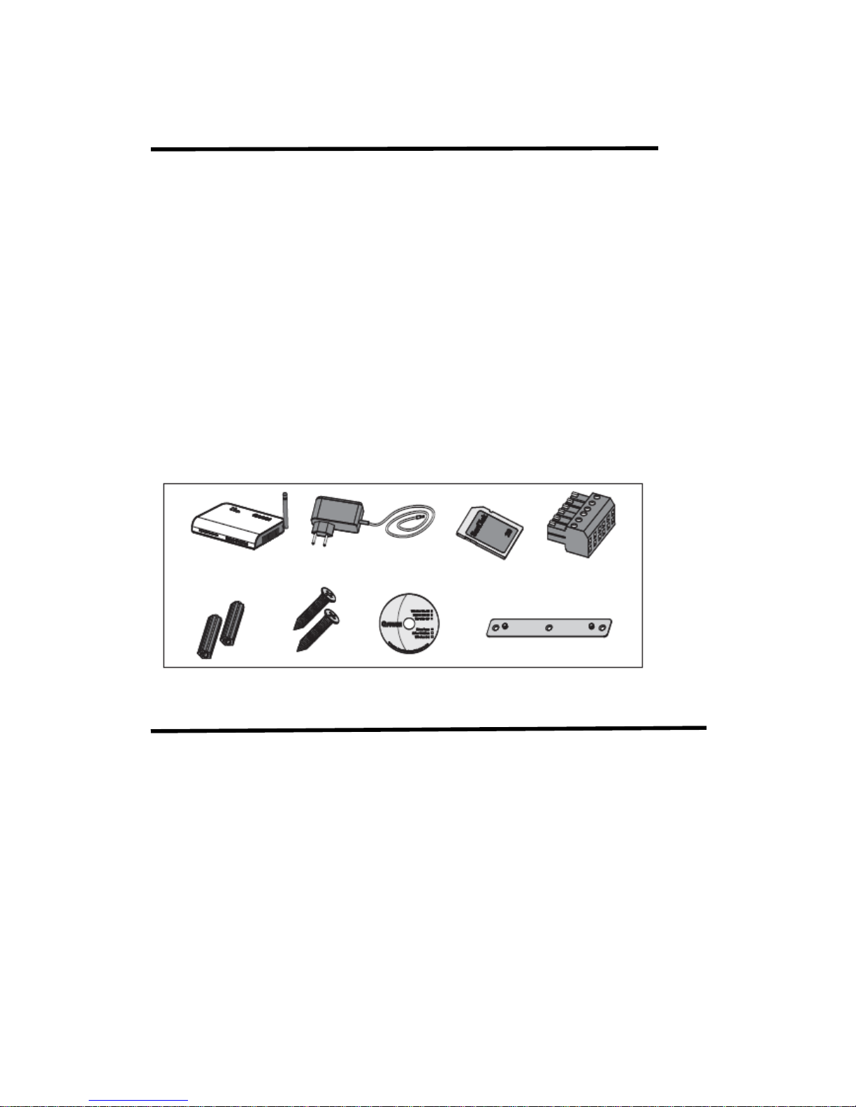
2.2.1 Packing List
The Shine WebBox and accessories can be found as below.
Label Name Amount
1 Shine WebBox 1pcs
2 5V Power Adapter 1pcs
3 2G SD Card 1pcs
4 Terminal (RS485 connection
and ripple control receiver) 1pcs
5 Plastic Column 2pcs
6 M3.5*20 Screw Spike 2pcs
7 Shine WebBox Instruction CD 1pcs
8 Bracket 1pc
Page 9

2.2.2 Serial Number and Check Code
The serial number(S/N) and check code (C / C) is marked on the WebBox’s packaging
box and WebBox’s body, serial number consist of 10 digits with letters and numbers,
the check code (C / C) consist of 5 digits with letters and numbers. All the serial number and
check code are unique, to identify each WebBox. If you want upload inverter data
from WebBox to ShineServer, you need add WebBox to your plant with the unique
serial number and check code, the “check code” is “validate code” in the shine
server.
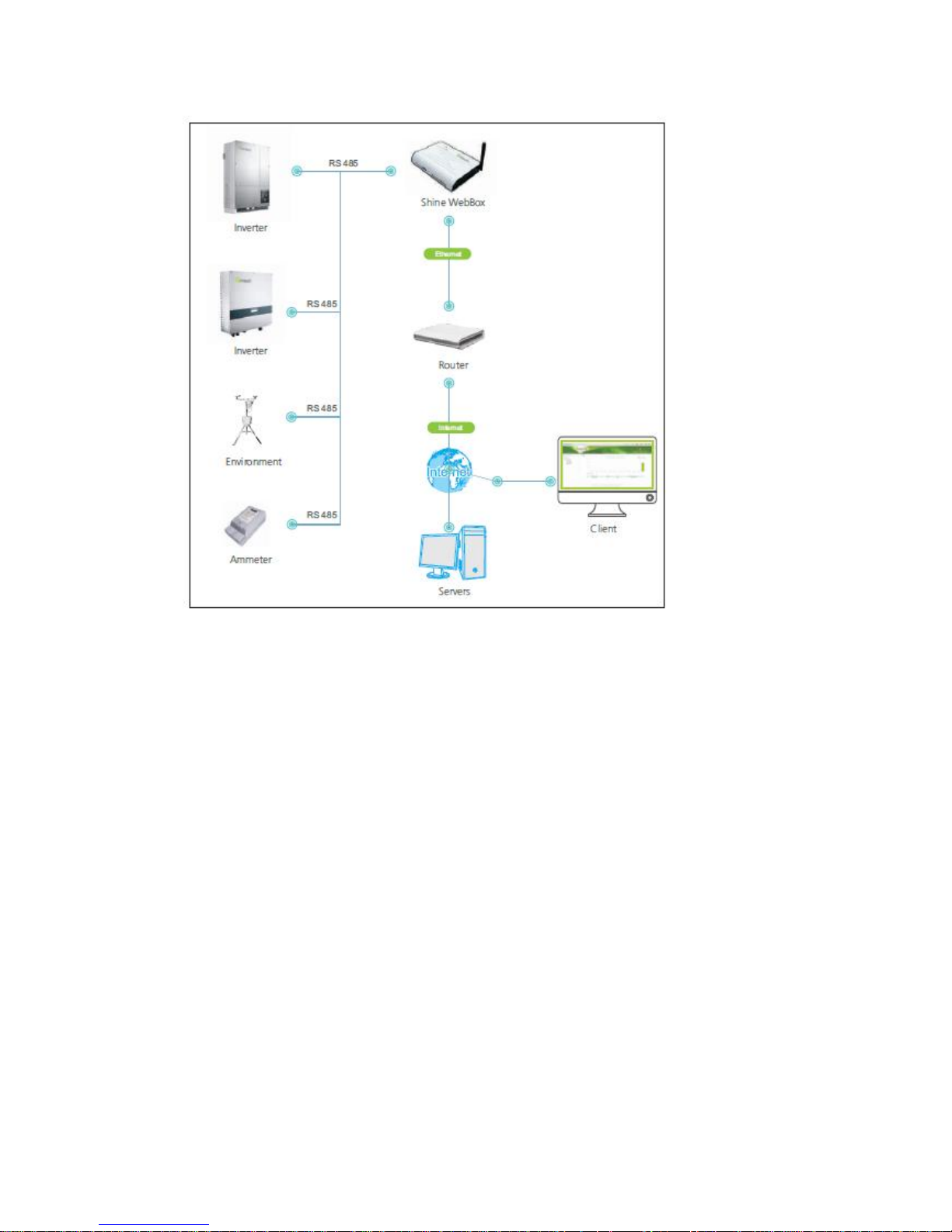
2.3 Shine WebBox Function Introduction
Shine WebBox can monitor the PV devices via RS485 cable, see below picture of the
monitoring system.
Shine WebBox can connect to a local area network via router or switch machine. You
can access to WebBox web server with WebBox IP address to check monitoring data,
or configurate WebBox network information, then WebBox can upload the inverter
data to Growatt ShineServer, you can visit your ShineServser account and check
plant real time data in anywhere with ShinePhone APP or ShineServer website. Shine
WebBox can communicate with inverters by RS485, and keep the data into the
internal RAM or SD card.
Page 10
3 Installation and Connection
3.1 Requirements for Installation Location
The installation and operation environment need consider below tips:
Indoor installation
Temperature: from 0 – 45 degree (℃)
Avoid humid environment
Avoid being exposed to directly sun radiation
The maximum cable length of RS485 communication bus is 1200m
The maximum length of network cable used to connect switch or router is not
more than 100m.
Page 11
3.2 Shine WebBox Installation
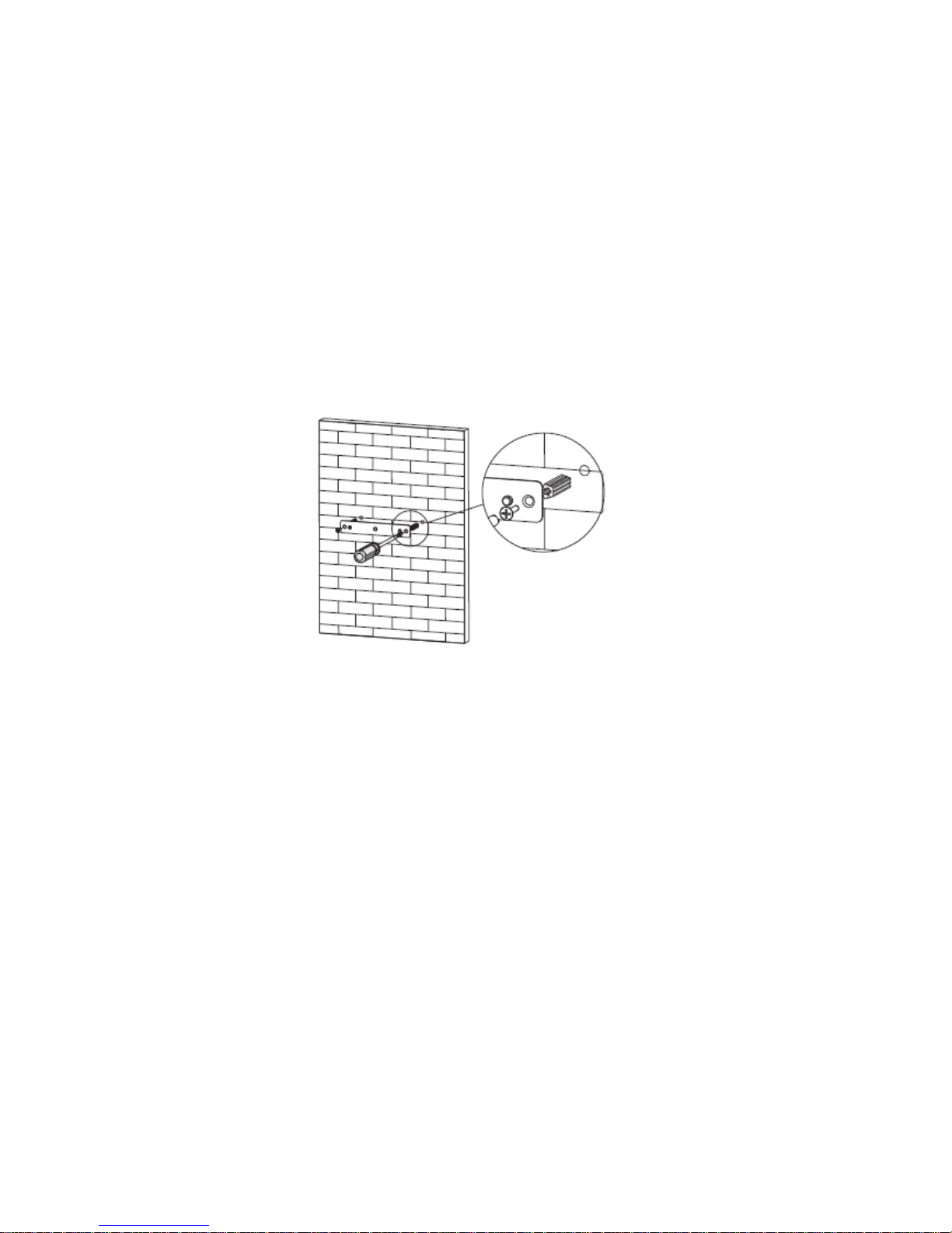
3.2.1 Wall-mounted Installation
Installation Procedure:
1. Install the bracket on the vertical plane of the wall. Dig two holes according to the
dimension of the bracket, there are two screw holes. Use hammer or suitable tools
to hit the plastic columns into the two hold on the wall. Use Philips screwdrivers to
screw the screws into the columns to install the bracket firmly onto the wall.
Page 12
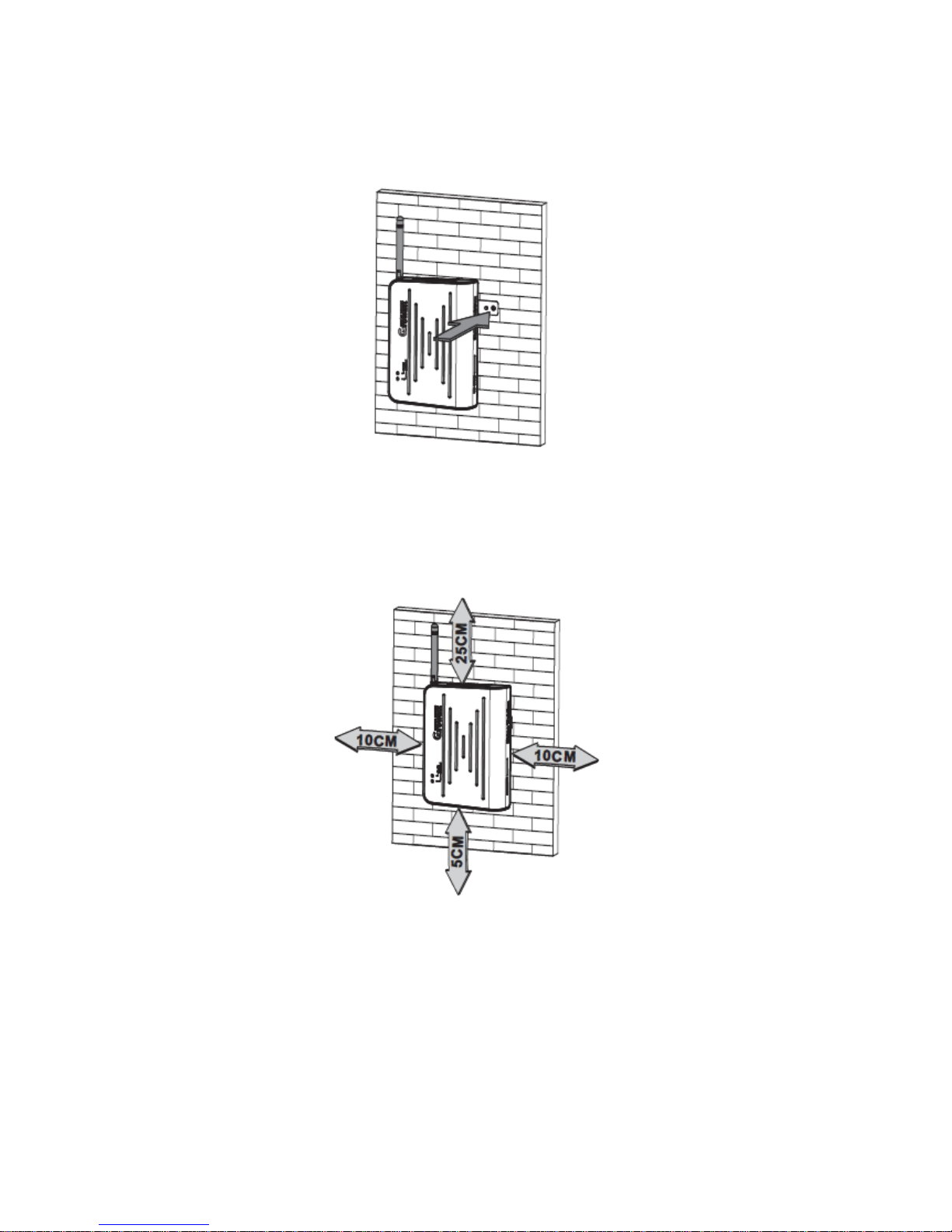
2. Hang Shine WebBox onto the bracket through the calabash ports in the back of
Shine WebBox.
3. Finish the mounting of Shine WebBox, notice the clearance of mounting.
4. Connect all inverter’s RS485 in parallel with RS485 cables, then connect to the
WeBox RS48 connector of WebBox.
5. Connect the network cable: insert the network connector to the LAN port on Shine
WebBox.
6. Insert the SD card: Insert the SD card into the SD card port on Shine WebBox,
Page 13

Note: The SD card must be inserted before powering on Shine WebBox, otherwise
the SD card would not be recognized.
7. Connect the power line: connect the power line to the power port on Shine
WebBox.
8. Turn on the power switch to power on Shine WebBox.
3.2.2 Horizontally Installation
Installation Procedure:
1. Set Shine WebBox on a horizontal plane.
2. As to the rest steps, please refer to aforementioned step 4-8 in chapter 3.2.1.
3.3 Network Connection
3.3.1 Setting IP Address of PC
The default network configuration of WebBox is listed as below.
IP address: 192.168.1.230
Subnet mask: 255.255.255.0
Default gateway: 192.168.1.1
Note: Before connect to the WebBox internal web page, please make sure your
laptop /PC’s IP address are in the same network segment with the WebBox.
Page 14

1. Window XP OS
Open the program “Network” → open “Local Connection” → Choose “Internet
Protocol version 4 (TCP/IPv4)” → double click to open “Internet Protocol
TCP/IP Properties” → “Use the following IP address”, make sure the IP address of the
PC and Shine WebBox are in the same network segment. You can set the IP address
referring below pictures:
Page 15

2. Windows 7 OS
Click to open “Network” → “Connection to a network” → “Local Connection” →
“Internet Protocol version 4 (TCP/IPv4)”, change the IP address of the PC, make sure
the IP address of the PC and Shine WebBox are in the same network segment. You
can set the IP address referring below pictures:
Page 16

3.3.2 Connect WebBox to the PC
1. Power on the Shine WebBox, and connect WebBox to the PC with network cables
via the RJ45 ports.
2. Set the IP address of CP or laptop to be in the same network segment, refer to
section 3.4.1, if already set, go ahead.
Note: Before connect to the WebBox internal web server, please make sure your
laptop or PC IP address are in the same network segment with the WebBox.
3.3.3 Connection via Network Router
1. Set the gateway of the router to be 192.168.1.1, if don’t know how to configure
please contact your network manager.
2. Connect the PC and Shine WebBox through the network ports of router and make
sure they are work in the same local area network.
3. Check the IP address and gateway of the PC to confirm that the PC connected to
router, PC and Shine WebBox are in same network segment.
Page 17

3.3.4 Connection via Network Switch
1. Connect the PC and Shine WebBox to the network ports of network switch.
2. Set the IP address of the PC and Shine WebBox to be in the same segment.
3. Power on the PC, Shine WebBox and network switch then it’s available to get
access to Shine WebBox internal server on the PC.
3.4 Connection to PV System
Shine WebBox can monitor Growatt devices in PV system, such as the inverter,
weather station and smart meters via RS485 communication.
3.4.1 RS485 Connection
1. Please refer to below picture for the RS485 cable connection, the inverter RS485 T+
corresponding to the Shine WebBox COM port 2#. The inverter RS485 T- corresponding to the
Shine WebBox COM port 4#, it’s also similar connection with Smart meter, combiner box,
weather station, and anti-reflux box. RS485A corresponding to Shine WebBox COM port 2# ,
RS485B corresponding to Shine WebBox 4# , Ground corresponding to Shine WebBox 8#.
Note: RS485 shielded cable must be grounded to avoid interference with communication stability.
Page 18

3. Old version inverter with below connect interface, connection as follows:
2. While monitoring several inverters together, inverters are in parallel connected
and then connected to Shine WebBox. The maximum number of inverter can be
monitored by Shine WebBox is 32 units.
3. The monitoring of smart meter and environment monitor is similar to inverter,
smart meter or weather station and inverters in parallel and then connect to Shine
WebBox with RS485 cables.
Note: Shine WebBox can only monitor the inverter,weather station, smart meter
from Growatt.
4 Internal Server Setting
4.1 Access to WebBox Internal Server
Before access to WebBox internal server, please make sure all network cables are
connected well, and the IP of the PC are correct, then open PC browser, enter
ShineWebBox COM port
Page 19

192.168.1.230 in the address bar. To get access to WebBox internal server from PC,
please make sure the IP address of PC and WebBox are in the same segment.
Note: when WebBox connects to local network, please confirm the IP address
192.168.1.230 is not occupied by other device. Otherwise the IP addresses will be
conflict, you can’t get in to WebBox internal web service.
1. Below is the Home page of WebBox internal server.
2. Click “Record” to view the online data of inverters, smart meter, combiner box,
weather station and anti-flux device.
Page 20

3. Click “Back Home” to return to the home page, click “Parameter” to WebBox
parameter page, where you can check WebBox information and do some setting, see
below picture of “Parameter” page:
4. Shine WebBox will search inverters according to the inverter address range setting.
Any new inverter is detected, will display in the “Record” page, and will update
inverter data automatically.
5. Log out from the Shine WebBox internal server when you finish visiting, to do so,
just close the Web browser.
Page 21

4.2 Shine WebBox Settings via Internal Sever
Shine WebBox settings include: system setting, date and time setting, data upload frequency
setting.
4.2.1 System Settings
4.2.1.1 Shine WebBox Information
In the "Parameter" interface, you can view the Shine WebBox device information, including the
Shine WebBox serial number, check code, device model, hardware version, and software version.
As shown in Figure 4-4:
Figure 4-4
4.2.1. 2 Set Network Address of Shine WebBox
Shine WebBox address settings include: IP address, subnet mask, gateway and DNS settings. As
shown in Figure 4-5 below, if the network IP address of the Shine WebBox is the same as the
three digits in front of the gateway, you only need to set the IP address to Shine WebBox, no
need to set the subnet mask, gateway or DNS.
Figure 4-5
1. Log in to the Shine WebBox internal server page via local access and click "Parameter" to get
into the parameter settings page.
2. Find “local_ip”, enter the fixed IP address your plan for the WebBox, the default
address is 192.168.1.230, and you can change it to 192.168.1.240, default value is as
Page 22

following picture.
3. The subnet mask of the Shine WebBox and that of the network or router which
Shine WebBox accesses should be the same.
4. Set the default gateway of the Shine WebBox same as that of the router which
WebBox connects to. Please confirm the default gateway is compliant with the
network.
5. Normally DNS is equal to the default gateway. Also you can set the DNS same as
the network.
6. After configuration all parameter above, click “save” bottom. After setting the IP
address successfully, restart the Shine WebBox, then you can get access to the
WebBox with the new IP address via browser.
Figure 4-7
4.2.1.3 Set IP Address of the Server
Usually you don’t need set the IP address of this part, because WebBox will connect to server
with the default domain url.
If WebBox can’t connect to Shine Server with domain url, you can set the IP address as below
steps:
1. In the "Parameter" interface, "Server_ip" part, modify the ShineServer IP to 198.11.169.241
(oversea Shine Server IP address),as shown in Figure 4-8:
Figure 4-8.
2. Click "Save" to save the change, and after done, WebBox will upload data to the server.
Page 23

If WebBox is working in a local Network, and update monitoring data to a local
server database, then you need change the "Server_ip" to the IP address of the local server
database.
4.2.1.4 Set Domain Url of Shine Server
"Parameter" page, in the "Server_url" part, you can modify the ShineServer domain url.
International user server domain url is: server.growatt.com
Chinese user server domain url is: server-cn.growatt.com
The default domain name is "server.growatt.com", as shown in Figure 4-9. If you visit the Shine
WebBox internal server and found the domain url not correct, please change to
"server.growatt.com" (International User). Then make sure Shine WebBox uploads data to the
Shine Server.
Figure 4-9
4.2.1.5 Set Inverter COM port Address Range
1. "Parameter" interface, settings of inverter address range, " Address_start" and
"Address_end" is the range of inverter COM address, the default start from 1, and end with
32. As shown in Figure 4-10, the range of the start address can be modified, but the start
address must be less than the end address. All of the monitored device must be within the
range, otherwise the inverter beyond the range can’t be monitored.
2. Click “save” button, wait the feedback of configuration has been carried out
successfully.
4.2.2 Set Polling Interval Time
1. In "Parameter" page, the "Delay time (S)" is the polling interval time setting, in the
drop-down list, you can choose "1.5s, 2s, 2.5s, 3s,", the default is 2S no need to change, as
shown in Figure 4-11.
Page 24

Figure 4-11
2. Click "Save" to complete, if you change the time
4.2.3 Set Date and time
Change the time on the Shine WebBox internal server page
1. Check "Enable_write" after "System_time". Figure 4-12 Set the system time.
2. Enter the time and date to be changed, click "Save", save successfully, and become time for the
WebBox.
4.2.5 Set Weather Station and Smart Meter
When the Shine WebBox is connected to weather station or a smart meter, you need to enable
this feature through the Shine WebBox internal server settings.
1. If there is a weather station in the system need monitored, please enable it first, in
"Environment: address" under the "Parameter" interface, select on in the drop-down list, click
"Save" under the page. The Shine WebBox enables the weatherstation monitor.
Note: The weather station COM address default is 36, you don’t need to change it on WebBox
internal page, also no need to change the COM address of weather station.
3. If there is a smart meter, similar, only need enable it, "Ammeter: address" right side, in the
drop-down list select "ON", and click "Save" button.
Note:
1. Only the smart meters and weather stations buy from Growatt can be monitored by
WebBox.
2. Only after enabled these function, then you can see monitoring data on Growatt and
Growatt Server, and for rated function, such as anti-reflux function via WebBox.
4.2.6 Set Power Adjustment, Master and Slave
In the "Parameter" interface under the "Power Adjust" after the drop-down list, select "ON", in
Page 25

the back of the drop-down list, select "Host", and click "Save" to open the Shine WebBox power
adjustment. As shown in Figure 4-15 to open the power adjustment, in the same local network,
only one "host", all other settings for the "slave".
Note: Only after enabled these function, then it will work, otherwise, system may not work
correctly.
Figure 4-15
4.2.7 Set Anti-reflux Meter and Anti-reflux Switch
In the "Parameter" interface, "Anti_reflux_device" is to enable the anti-reflux function, the
default address is 38, you don’t need to change it, if your system with an anti-reflux device,
please switch it on by select “ON” in “Ammeter –OFF/ON” drop list. Note: There is no
corresponding function device, prohibit the opening of this switch, otherwise it may cause the
equipment is not working properly.
Figure 4-16
4.2.8 Set Anti- reflux Power
In the "Parameter" interface "Anti reflux power" is for setting anti-reflux power
Note: Positive number means that can take power from the grid, can not appear countercurrent.
A negative number indicates that a power can be transmitted to the grid, allowed a certain
countercurrent.
For example:
1. Set the value to 0.2KW, means allow use 0.2KW from grid.
2. Set to -0.2KW, means allow deliver 0.2KW to grid.
Figure 4-17
Page 26

4.2.9 Set Combiner Box Address and Switch
In the "Parameter" interface, "Combiner Box: address start" after the text box to set the start
address, the default value is "41", you don’t need to change it.
In the "address end" after the text box set the end address, the default value is 50, followed by
the check box for the fuse box switch.
Note: There is no corresponding function device, prohibit the opening of this switch, otherwise it
may cause the equipment is not working properly.
Figure 4-18
4.2.10 Inverter Model Selection
In the "Parameter" interface under the "Inverter type" after the drop-down list is now the
inverter model, temporarily only support Growatt inverter.
Figure 4-19
4.2.11 Inverter Fault Indication
There are two ways to indicate the inverter fault:
1. The status LED of the Shine WebBox will turn to red, accompanying with beeping
for 1 min.
2. In the integrated server interface of the Shine WebBox, the data about the
inverters are shown in red.
Page 27

5 Uploading Data to Shine Server
5.1 Registration and Login
On Shine WebBox internal server, you can only check the real-time data. But you can check your
plant data at anytime in everywhere from Shine server account, Shine WebBox can upload all
your system information to Shine Server database every 5 minutes, you can check real-time data
and history data on Shine server. First, you need register an Shine server account.
(1) Login Growatt Shine server
The international user server domain url is: http: //server.growatt.com
The Chinese user server domain url is: http: //server-cn.growatt.com
Figure 5-1
(2) Click ”New User”, and fill in the rated information, click on "Register".
Note: "Datelog SN" and "datalog valicode " you can get from ShineWebBox internal server, it’s
"serial number" "Check_code" in "paramerer" page, see Figure 4-3.
Page 28

Figure 5-2
5.2 View the Monitoring Data
(1) After register, it will automatically jump to the Shine Server main interface. Click on the
"power plant" → "plant data", as shown in Figure 5-3, the information displayed for the daily
power chart of the plant. In drop-down list "select Datalog", you can choose to see inverter data
and chart.
Figure 5-3
Page 29

(2) Click "Power plant" → "Device list" to view real-time data such as " Datalog,
"Inverter",”Storage”, "Environmental Monitor", " Electric-meter " and " Convergence box "
6 Power Management
Shine WebBox power management is composed of active power reduction and
reactive power control components. To enable power management, a ripple control
receiver is required. This function is available when user activates it. The COM ports
of the Shine WebBox are shown as below. Pin 1,3,5,7,9,11 are used to connect the
ripple control receiver.
Page 30

6.1 Active Power Reduction
There are 4 power levels, 100%, 60%, 30% and 0%. The connection between ripple
control receiver and Shine WebBox is shown as below.
The output power of inverter depends on the operating relay. The detail information
is shown as below. Pin 1 is connected to 3.3V dc source.
Pin Status Explanation
1 3.3V DC source Powering relays
3 100% output power When the relay corresponding to pin 3
actions, the inverter outputs 100% of
nominal power.
5 60% output power When the relay corresponding to pin 5
actions, the inverter outputs 60% of
nominal power.
7 30% output power When the relay corresponding to pin 7
actions, the inverter outputs 30% of
nominal power.
9 0% output power When the relay corresponding to pin 3
actions, the inverter outputs 0% of
nominal power.
Page 31

6.2 Reactive Power Control
There are 4 power factor levels, 0.99, 0.98, 0.97, and 0.95. The connection between
ripple control receiver and Shine WebBox is shown as below.
The output reactive power of inverter depends on the operating relay. The detail
information is shown as below. Pin 11 is connected to 3.3V dc source.
Pin Status Explanation
9 0.99 PF When the relay corresponding to pin 9 actions,
the power factor of the output power is 0.99
7 0.98 PF When the relay corresponding to pin 9 actions,
the power factor of the output power is 0.98
5 0.97 PF When the relay corresponding to pin 7 actions,
the power factor of the output power is 0.97
3 0.95 PF When the relay corresponding to pin 9 actions,
the power factor of the output power is 0.95
Page 32

6.3 Manage Active and Reactive Power Together
If active power and reactive power need to be managed at the same time, connect
the Shine WebBox with two ripple control receivers as below.
7 Device Maintenance
7.1 Firmware Update
There are 2 ways to update WebBox firmware:
1. You can update WebBox firmware by using a USB flash disk, please contact Growatt service
department for the latest firmware version and update guide.
2. If your WebBox is well monitored by Growatt Shine Server, Growatt engineer can help update
your WebBox firmware remotely, just make sure your WebBox online.
7.2 Restart WebBox
1. You can turn off Webbox via the power switch, and turn on it again.
2. Restart from the WebBox internal server page as below picture, and click “Save”.
Page 33

7.3 Reset the Shine WebBox
Before rest the Shine WebBox, please login Shine WebBox internal server, and in bottom of
“Parameter” page:
1. Select “Enable_Reset” as below picture.
Figure 7-1
2. Click on “save”, then Shine WebBox would restore factory settings after restarts.
Note: After reset to factory setting, you can login WebBox internal server with the
default IP address, refer to 3.4 Network Connection.
7.4 Clearing up the Record
1. In bottom of “parameter” page, select “Enable_Clear_record”.
Figure 7-1
2. Click on “save”, all the devices information records would be wiped out after the
Shine WebBox restarts.
Page 34

7.5 Troubleshooting
Problem
Cause
Solution
No inverter was found
Inverter address was not
correctly
Reset inverter address, make
sure every inverter address is
unique and in the allowed
range
Can't access to WebBox
internal server via PC /
laptop
WebBox and the
PC/laptop are not in the
same network segment
Make sure the WebBox and
PC/laptop, router in the same
segement, or contact your
network administrator for help.
Can't access to Growatt
Shine Sever
PC or laptop not connect
to internet correctly
Make sure PC or laptop connect
to internet, and make sure visit
the right website
www.growatt.com
WebBox can't deliver
data to Growatt Shine
Sever
WebBox IP address is
occupied by other
equipment in the same
network.
Change WebBox IP address or
contact network administrator for
help.
7.6 Maintenance and Care
1. Regularly check if webbox working normally, and if there is any damage or dirt on
WebBox.
2. WebBox can only be used indoor, protect WebBox from wet conditions and
direct sunlight.
Page 35

8 Technical Data
8.1 Shine WebBox
Mechanical data
Width*height*depth 185mm* 125mm * 30mm
Net weight 420g
Environmental conditions
Ambient temperature 0 ℃… 45℃
Degree of protection IP 20
Mounting location Indoor
Communication
Rs485 communication Maximum 30 inverters
Wireless communication ZigBee ,maximum 15 inverters
Rs485 communication range 1200m,STP
ZigBee communication range 300m,obstruction free
8.2 Plug-in Power Supply
Power supply
Input 100~240V 50/60Hz
Output 5Vdc,2000mA
Page 36

8.3 Accessories
8.3.1 SD Card
There is a SD card of Shine WebBox with 2G memory, and valid for 5 years. The SD
card storages WebBox system files and monitoring data, when WebBox is not
connect to Shine Server correct, and upload to Shine Server when on-line again.
8.3.2 RS485 Cables
To ensure the stable communication between the Shine WebBox and inverters, we
suggest use RS485 cable that consists of STP (shielded twisted pair) . The maximum
length of RS485 communication is 1200m. Below is suggestion for the RS485 cable:
Cable length Specification
< 200m 2*0.3mm2, twisted-pair, bushing
200-500m 2*0.5mm2, twisted-pair, bushing
500-1200m 2*0.75mm2, shielded twisted pair, bushing
Page 37

9 Contact
If you have technical problems concerning our products, please contact the Growatt
serviceline.
GROWATT NEW ENERGY
Building B, Jiayu Industrial Zone, #28 Guanghui Road, Longteng Community, Shiyan,
Baoan District, Shenzhen, P.R.China.
Service hotline: +86 755 27471942
E-mail: service@ginverter.com
Website: www.ginverter.com
GR - UM - 010 - 01
 Loading...