

Page 1
GROWATT NEW ENERGY CO., LTD
No.12 Building, Xicheng Industrial
Zone, Bao’an District, Shenzhen, P. R.China
+ 86 755 2747 1900
+ 86 755 2749 1460
service@ginverter.com
www.ginverter.com
T
F
E
W
Operation Manual
ShineVision
GR - UM - 0 07 - 01
Page 2

Product Overview
Basic Operations and Display of Functio ns
Contact
Table of Contents
1
2
3
2.1 Che ck of softwa re version a nd clear
2.2 Cod e-matchi ng operati on
2.3.1 Cu rre ncy symbo l set ting
2.3.2 In com e coeffic ient sett ing
2.3 Bas ic Setting
2.3.3 CO 2 coe ffic ien t setting
2.3.4 Da te se tting
2.3.5 Time set tin g
2.3.6 Tem peratur e uni t setting
2.3.7 Bu zze r setting
2.5 Def ault inter face switc hing enqui ry
2.6 Def ault inter face displ ay
2.7 Rea ding of Data o f Emitter No .1 to 6
2.4 Dat a storage
Page 3
1 Product Overview
ShineV isi on, whic h c ons ists of a p owe r m oni tor and a n umb er of tra nsmitte rs, can
achiev e 1 to 6 m oni toring modes . The tran smi tters transm it th e pow er da ta co lle cted
fro m a pho tovolta ic inv erter to the moni tor and disp lay the dat a o nto the moni tor
screen , a s alon g as dat a o f gene rat ed ene rgy, the gross gen erat ed ener gy and the
genera tio n i ncome obtaine d f rom the abov e-menti one d d ata thro ugh some simple
calcul ati ons. We ca n als o see 3-phas e AC v oltage, two-wa y PV v oltage, indoor
temper atu re, da te an d time, as we ll as C O2 emissi ons .
2Basic Operations and Display of Functions
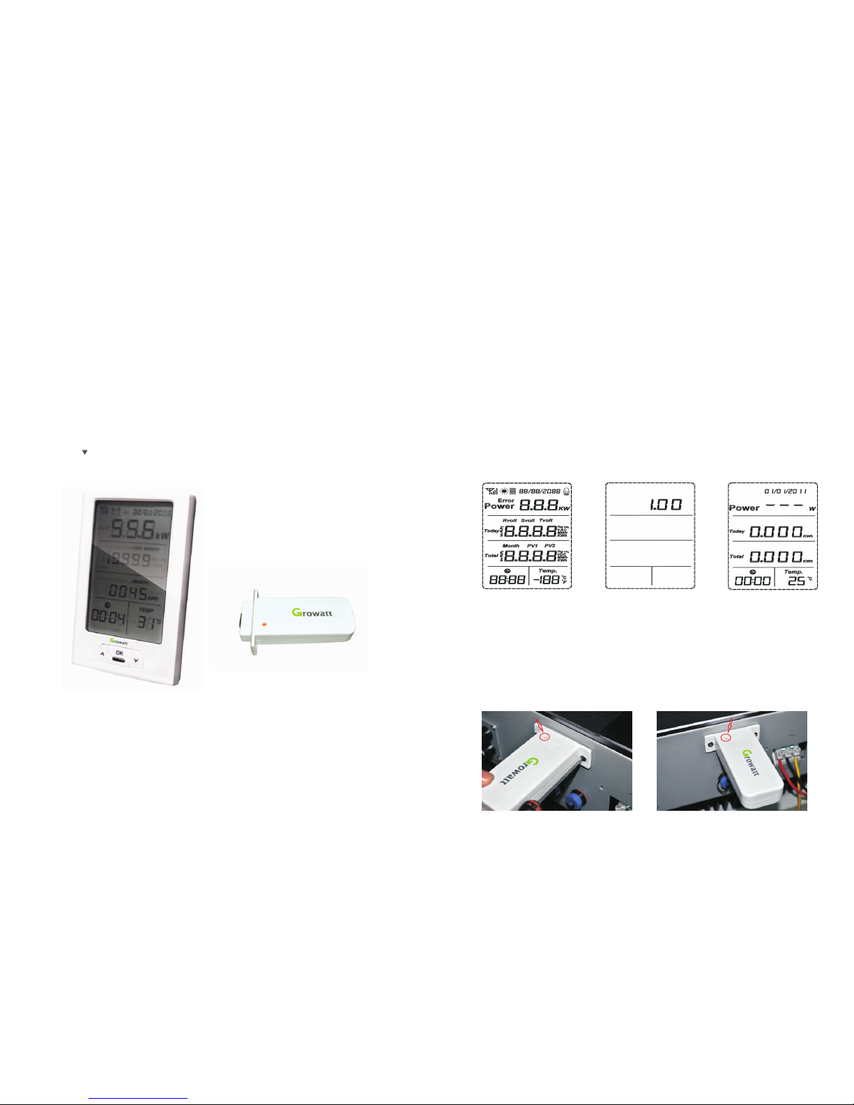
2.1 Che ck of softwa re version a nd clear
Insert p owe r sup ply ( or batter ies ) aft er pre ssi ng “u p” and “down” ke ys co ncu rren tly,
LCD will display 3 seconds in full screen as shown in Figu re 2. The red LED light
flashe s qui ckly twic e 3 sec onds late r (0. 5 second pe r tim e), then re lease the “ up” a nd
“down” keys, LE D li ght will be on f or a long tim e, L CD w ill sho w th e ve rsi on N o. o f
the so ftw are as s hown in Fi gur e 3. LED ligh t w ill turn off 3 se cond s l ate r, an d L CD
res ets to the defa ult int erfa ce as sho wn in Figu re 4. The rele van t info rma tion h as
been cle ared.
Note: Fa cto ry defaul t dat e: 01/01/ 201 1 (dd/ mm/ yy) , defa ult t ime : 00:0 0.
Figure 2 Figure 3 Figure 4
Notes : Po wer up t he mon ito r via th e pow er ada pte r, whic h is del ivered in the
packag e box . But for con ven ience, so met imes i t’s ava ila ble to u se ba tte ries .
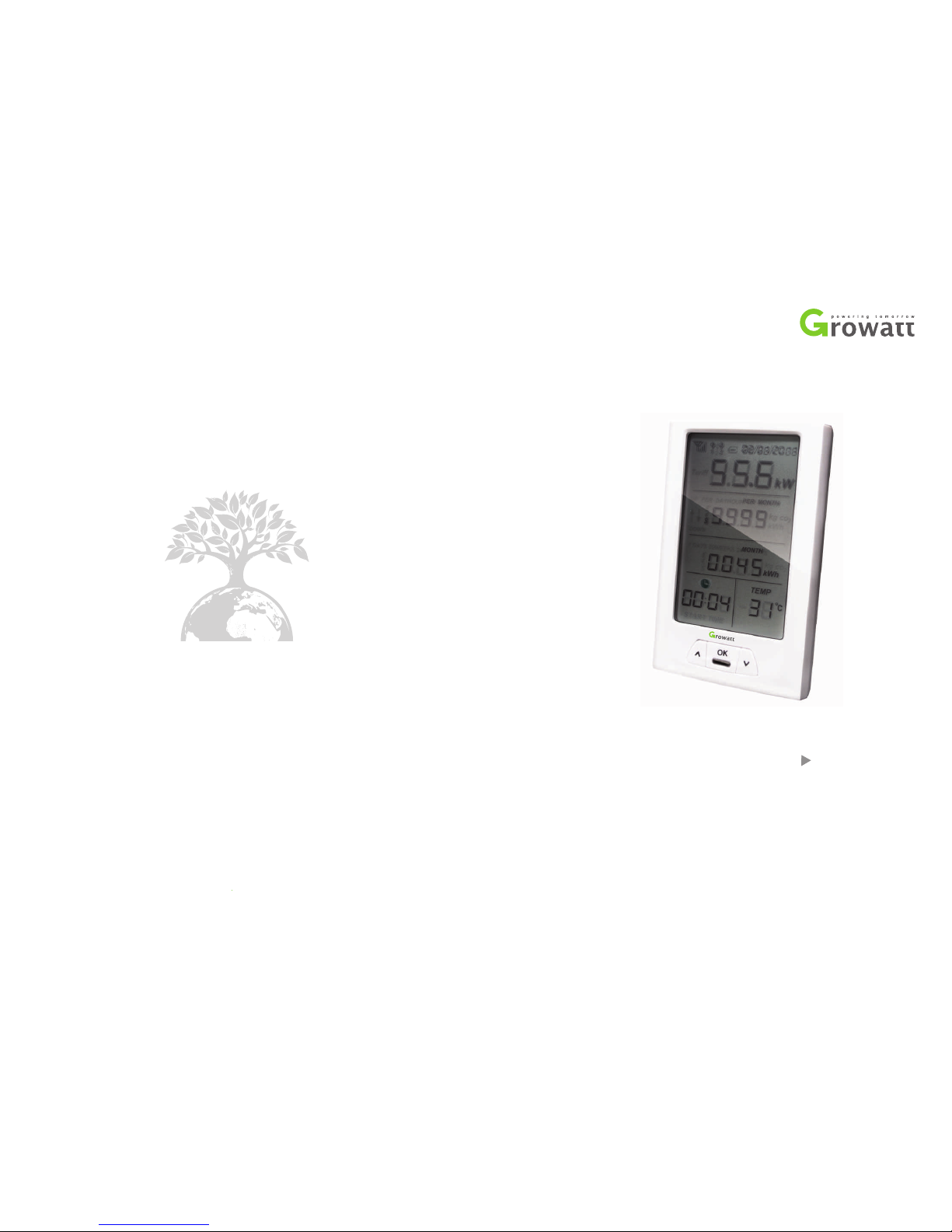
Figure 1 P ower Moni tor a nd Tran smitter
Overvi ew
2.2 Cod e-matchi ng operati on
Before code -mat chi ng oper ati on plea se connect the transmi tte rs firm ly to i nve rters
via the RS 232 p ort (figu re5). Det ail ed inform ati on ref ers t o the ne xt pa rag raph .
Figure 5 C onnect th e tra nsmitte r to in vert er
Page 4

Figure 9
Figure 1 0
Note: When pres sing ”Ok” afte r a ll ite ms are set, the LED lig ht wil l f lash t wice to
indica te th e setting a re verifi ed va lid
2.3.1 C urrency sy mbol setti ng
Pre ss “O K” ke y to en ter t he mo dul e of cu rrency symbo l set tin g as sh own i n Fig ure 1 0
when the c urrency s ymb ol flashe s. No w symbol fl ash es.
Pre ss “dow n” k ey, s ymb ol flashes, press th e “d own ” ke y again , $ flash es. The n
pre ss “u p” ke y to co nvert the orde r. When a curr ency symbol fl ash es, p ress “ OK” k ey
to s ele ct the cu rren cy s ymbol. T hen , the cur renc y sy mbol sto ps fl ash ing , mea nwh ile,
you ente r the m odule of in com e coeffic ient sett ing , and “0 ” in 0. 163 f lash es.
If sett ing for cur renc y sy mbo l is not necessa ril y req uir ed, pres s “d own” key to ente r
the modu le of i ncome coe fficien t set ting.
Notes: sup pose t hat $ i s selecte d as the cur renc y symb ol, the dis play o f curr ency
symbol wil l ch ange to the cur ren cy symbo l se lec ted at th is s tep .the default c urrency
symbol o f the s ystem is $.
2.3.2 I ncome coeffic ient setti ng
After the cu rrency sym bol is se lected, pr ess “O K” for a short whil e to ente r the
module of i ncome c oeffici ent setting, as s how n in Figu re 10. At the tim e wh en the
“0” of 0. 163 flas hes , pre ss “U p” or “Do wn” t o adjust its v alu e, ra ngi ng fr om 0 t o 9,
and pre ss “ OK” to c onf irm afte r ad jus tment, then the “ 1” o f 0. 163 will flash; press
“Up” or “Dow n” t o adj ust its v alu e, ra ngi ng fr om 0 t o 9, a nd p ress “OK” to c onfirm
Notes: A nte nna symbo l is no t disp lay ed if c odes a re no t matc hed , vic e vers a, di spl ay
once the c ode s are su cce ssfully m atc hed.
Figure 6 Figur e 7 Figu re 8
2.3 Bas ic Setting
In the def aul t int erface, p res s “OK” key for qui te a wh ile , 3 sec onds later, the red LED
flashe s qu ickly tw ice and then rel ease the key to ent er b asi c settin g, L CD d isplays as
shown in F igu re 9, at this time , the currency sym bol will fla sh, swit ch ove r a mon g
variou s func tio n m odu les thro ugh “down” key. Set ting sho uld follow the order of
curren cy sy mbo l (sy ste m defaul t as ), inc ome c oeffici ent (sys tem defa ult as 0. 163 ,
emissi on c oeffici ent (sy stem defaul t as 0.99 7), date , time, temperat ure unit (syste m
defaul t a s ℃ ) , buzz er switch (sy stem de fau lt as st atus ), pres s “ up” key to
conver t th e ord er. Re sto re to the defau lt i nterfac e as sho wn in Fig ure 6 if ther e is no
key operati on within 1 minu te in the int erface of bas ic sett ing s, or rest ore as all
option s are set.
)
After t he power is energ ize d, the de fault in ter face dis pla ys, p ress “do wn” and “ up”
keys sh ort ly a nd selec t th e ch anne l No . (o ptional fro m channe l No .1 t o 6), and press
the “do wn” k ey f or ab out 3 sec ond s unt il the re d LED light qu ick ly fl ash twic e , then
rel eas e it. After qu ite a while, s imu ltan eou sly p res s the red b utton on tran smi tter for
a whil e u ntil th e r ed LED lig ht quickly flas h t wic e , you will automat ica lly enter th e
code-m atc hing of the chan nel as s how n i n Figur e 6 . An ten na sym bol flashes once
per sec ond, LCD disp lay s as s hown in Figur e 7 . A fter rele asi ng th e red but ton o n the
transm itt er L CD w ill dis pla y as sho wn i n Figur e 8. Upo n th e succe ssf ul m atc hing of
codes, LCD will dis pla ys as sho wn in Figure 8, i n case of code-mat chi ng fai ls in 1
minute , LCD w ill displ ay th e defa ult i nte rfac e as Fi gure 4 .
.
Page 5

fro m 0 to 9, and pr ess “ OK” to co nfi rm af ter adju stm ent, the n the fou rth f igu re “1 ”
of the Year “ 2011” wil l fla sh; press “ Up” o r “Down” to adju st it s val ue,
rangin g f rom 0 t o 9 , a nd pres s “ OK” to c onf irm after ad jus tme nt, then the Month
01” wi ll fl ash ; pres s “Up ” or “D own” to adj ust i ts va lue, rang ing f rom 1
to 12, and p ress “OK” t o con firm afte r adj ustment , the n the Da y “01 ”
will fl ash; pre ss “U p” or “Do wn” to ad just its value, r ang ing f rom 1 to 31, an d pre ss
“OK” to c onf irm a fte r adj ust ment , then th e dat e wil l stop fl ash. Now t he in ter fac e is
res tored to th e sta tus as show n in Fi gure 9 a nd th e time star ts to f lash.
If there i s no need to se t dat a, pre ss “D own” to ent er th e time sett ing m odul e.
When the time s ymbol flashes , pres s "OK” for a shor t while to enter t he time
settin g mo dul e, a s sh own in Figu re 13, t hen the Hou r “0 0:” of w ill fla sh;
pre ss “Up” o r “Down” to ad jus t its val ue, rang ing from 00 to 23, a nd p ress “OK” to
confir m afte r adju stm ent, the Minute “:00” of will fla sh; pr ess “U p” or
“Down” to a dju st its va lue , ra nging fr om 0 0 to 59, and pres s “O K” to con fir m af ter
adjust men t, th en t he time s top s flashi ng. Now the i nte rfac e is rest ore d to t he s tatus
as shown i n Fig ure 9 an d “Temp .” flashe s.
2.3.5 Time sett ing
If there i s no need to se t tim e, pre ss “D own” to ent er th e tempera ture unit s ett ing
module .
Note: Wh en en tering ti me se ttin g, th e blo ck ind ica tes t he cur ren t syst em ti me.
Figure 1 4
Figure 1 5 Figure 1 6
after adju stm ent, then t he “ 6” o f 0. 163 wil l fl ash; pre ss “ Up” or “D own” to adj ust
its val ue, rang ing from 0 to 9 , and pre ss “O K” t o con fir m aft er a djustme nt, then the
“3” of 0 .16 3 wil l fl ash; pre ss “Up” o r “D own” to a dju st it s va lue, ran gin g fro m 0 t o
9, and press “OK” to c onfi rm after a djustme nt. At the m oment, “3” sto ps flas hin g
and the i nter fac e is re stored to the statu s as shown i n Fig ure 9 , the n “Kg C O2” s tar ts
to flash .
Figure 1 1
Figure 1 2 Fi gure 1 3
2.3.3 C O2 coefficien t setting
Pre ss “OK” f or a s hort whi le wh en Kg CO2 flas hes , the n yo u wil l enter t he se tti ng of
CO2 emi ssi on fa cto r, as s hown in F igure 11 . The def aul t val ue o f system is 0.997 . At
the tim e whe n the first fi gure “0” f las hes, press “U p” or “Dow n” to adj ust i ts value ,
rangin g from 0 t o 9, and pres s “O K” t o confir m af ter adjustm ent , then th e fi rst “9”
will flash ; pr ess “Up ” or “Down” to ad just its va lue, rang ing from 0 to 9, a nd p ress
“OK” to conf irm aft er adju stm ent, then the seco nd “9” will fla sh; pre ss “Up” or
“Down” to adj ust its valu e, ran ging f rom 0 to 9 , a nd pre ss “OK” t o c onf irm afte r
adjust men t, th en th e fig ure “ 7” wi ll flash ; pre ss “U p” or “Do wn” t o adj ust i ts value ,
rangin g fro m 0 to 9 , and p res s “OK ” to co nfi rm af ter adju stm ent. Now t he in ter face
is re sto red to t he st atus as sho wn in F igure 9 and t he date fla she s.
2.3.4 D ate settin g
When the dat e flas hes , pres s “OK” for a sho rt while t o enter the mod ule of date
s sett ing, as shown i n F igu re 12 , t hen the thi rd figu re “1” of t he Year
“2011” w ill f lash; pre ss “Up” or “D own ” to adjust i ts va lue, r ang ing
Page 6

Figure 1 7 Fi gure 1 8
Figure 1 9
Figure 2 0 Fi gure 2 1 Fi gur e 22
2.5 Def ault inter face switc hing enqui ry
1) See Fig ure 8 for def aul t interfa ce.
The f irs t line indi cat es, in defa ult, the tota l ins tantane ous pow er of eac h inverte r
connec ted . Whe n the p owe r is not le ss th an 10 00W, t he un it “k W/W” will be sh ift ed
to kW auto mat ically.
The se cond li ne i ndi cat es t he genera ted energ y, ge neratio n re ven ue and C O2
emissi ons o n the d ay. The t hree d ata a re dis pla yed o nce every 5 s in cy cle . The
sequen ce o f displ ay in c ycle is gener ate d en erg y, gen era tion revenu e an d then CO2
emissi ons , as shown in F igu re 17 to 1 9.
not be rese t u nti l t he begi nni ng of the next mont h o r e xecutio n o f r eset . T he tot al
genera ted e nerg y, tota l gen eration r evenue an d tot al CO2 e mis sions are a lways
stored a nd will not b e reset unt il da ta res ett ing is perf orm ed.
2.3.6 Tempe rature uni t setting
When “ Temp. ” flash es, press “O K” for a sh ort whi le to ente r t he temp era ture unit
settin g modul e, as s how n in Fi gure 14, the n ℃ ( def aul t sy ste m tempe rat ure uni t)
will flas h. Press “Dow n”, “℉ ” will fla sh; pre ss “Up ”, “℃ ” wil l flas h. When the
temper atu re u nit flashes , press “OK ” fo r a sho rt w hil e an d co nfi rm t he s ele ction o f
the cu rren t t emperat ure sy mbo l. A nd no w th e s ymbol s tops fl ash ing an d t he
interf ace i s rest ored to the s tat us as shown i n Fig ure 9, t hen f lashes.
If there i s no need to se t tem peratur e unit, pre ss “Down” t o ent er the buzz er se ttin g
module .
Note: Wh en en tering te mpe rature se tting, th e pla ce sho win g tem pera tur e indi cat es
the curr ent ambie nt te mperatu re in the cur rent unit .
2.3.7 B uzzer sett ing
When f las hes, pres s “OK” for a sho rt while to ente r the bu zzer se tti ng
module , as shown in Fig ure 15. Then will flas h. Pres s “U p” o r “D own” fo r a
short while , and you c an ma ke a s hift between and . A fter the s tat us of
the buz zer is se t well, p ress “OK ” to conf irm and t hen LCD w ill retu rn t o th e def aul t
interf ace .
If there i s no need to se t the b uzzer, pres s “Do wn” and the n LCD w ill re tur n to th e
defaul t int erface.
Notes: When choo sin g and p ressing “OK” , the buzz er will be opened a nd th e
sign of ri ng at t he up per right c orn er of L CD wi ll di spla y, as shown in F igu re 16. Whil e
choosi ng a nd p ressing “OK”, the buzzer wil l be clo sed and the sign of ring
will not d isp lay. Th e system de fau lt status o f the b uzze r is cl ose d.
2.4 Dat a storage
The gen era ted ener gy, gener ati on re ven ue a nd CO2 emiss ion s on the day a re s tore d
and will not be res et u nti l 0: 00 o f th e ne xt d ay o r ex ecu tion of re set. The genera ted
energy, g ene rat ion r evenue a nd C O2 em iss ions in t he m onth are also sto red a nd will
Page 7

LCD will a uto matical ly refres h its displ ay in t he defaul t int erfa ce.
2.6 Def ault inter face displ ay
The f irst l ine disp lay s i n default the total real -ti me power o f a ll phot ovol tai c
invert ers .
The second line display s th e ac tua l ge nerated energy, ge neratio n re venue and
CO2 em issions by all p hotovol tai c in ver ters on the day and the three data are
displa yed o nce every 5 s and i n cycle.
There are two modes in the third l ine. The first is to show the a ctu al
accumu lat ed g ene rat ed e ner gy, g enerati on reve nue and CO2 emi ssi ons by all
photov olt aic i nve rters in the m onth, as show n in F igu re 20 to 22 ; the sec ond i s
to sho w th e a ctua l a ccumula ted electric ener gy, g ener ati on reve nue and CO2
emissi ons by al l phot ovo ltaic inverte rs. Th e two mod es are di vid ed int o six
interf ace s and eac h in terf ace is displ aye d once ev ery 5s and in cyc le, a s sh own
in Figur e 17 to 22. The s equ ence of cyc le is f rom Tota l to Mo nth.
The four th li ne shows th e tim e and te mpe rat ure.
1.
2.
3.
4.
Notes: Whe n t he monitor receives error informa tio n o f phot ovo ltaic inverte rs, the
first li ne will d isplay “E rror” a nd its releva nt wrong co de (suppo sin g 00 0).
Meanwh ile , the b uzz er wi ll al arm t wice every five minut es (i f the buz zer i s set
opened ), as s hown in Figu re 2 6 an d t he L EC lamp will flas h on ce ever y s econ d. The
displa y re sults o f th e se con d an d th ird lines must be c orre spo nding t o ea ch o the r. It
means wh en th e second li ne di splays ge ner ated ener gy on t he day, the third li ne must
displa y the tota l gene rat ed energy or generate d energy of the mont h at the sam e
time. The dat a must be dis pla yed cor resp ond ing ly and in cycl e and the mea ns of
displa y in cy cle is Toda y-Tot al an d Tod ay-M ont h, as s hown i n Fig ure 17 t o 22.
Figure 2 6
There are two m odes in the thir d lin e, one showing t he ge ner ated ener gy, genera tio n
rev enu e and CO2 e mis sions in the m onth and the o the r sho win g the total ge nerated
energy, tota l gene rat ion reve nue and tota l C O2 emis sions. Two mode s are divided
into six i nte rfaces an d eac h interfa ce is d ispl aye d aft er eve ry 5s i n cyc le, as s how n in
Figure 17 to 22. Th e mea ns of disp lay in cycle is Today -Total-Toda y-M onth . Press
“OK” f or a s hor t w hile in the defa ult interfac e, you will ente r t he enq uiry of daily,
monthl y and tota l data. W hen e ntering the e nquiry inter fac e, th e his tor ical dai ly an d
total data wi ll b e displ aye d, a s shown in Figur e 17 . T hen, pres s “D own ” fo r a sho rt
while f or e nqu iry of g enerate d en erg y, gen era tion rev enu e an d CO2 emissi ons from
Today to Total in sequen ce, a s sho wn in F igure 17 to 19, an d for enqu iry o f gen erated
energy, g enerati on re ven ue an d CO2 emis sio ns fr om Toda y to M onth in se que nce, as
shown in Figu re 20 to 22. Or press “Up” for a short whol e, and you wil l see the
enquir y re sul ts i n the o pposite d irec tio n. T he d efa ult in ter face wi ll a ppe ar b y
pre ssi ng “OK” for a sho rt whi le in any in terface of en qui ry or whe n there is no
operat ion o f enquiry a t all i n 30s.
The four th li ne indica tes t ime and tem per atur e.
2) Press "Up" or “Dow n” for a sh ort while in the def aul t inter fac e (Figu re 8), then
you will en ter the en quir y of pha se volt age and tw o-circu it PV volt age for threephase A C of each cha nnel, as sho wn in Fig ure 2 3 (s howing t he e nquiry r esult of CH:
01 cha nne l; the enq uir y for other cha nne ls are sim ilar to it ). Afte r ente ring such
enquir y, pre ss “OK” for a shor t wh ile, an d th en y ou w ill enq uir y in seq uen ce a nd i n
cycle “Rvol t-- - PV1 ”, “S vol t--- PV2” and “ Tvo lt-- - PV1”, as sho wn in F igu re 23 t o 25.
If t here i s no press ing o n any e nqu iry i nterfac e wit hin 3 0s, t he in ter face will retu rn to
its defa ult s tatus in 30 s.
Figure 2 3 Figure 2 4 Figure 2 5
Page 8

Figure 3 0
3 Contact
If you hav e som e require men ts or probl ems c once rni ng Sh ineV isi on, pl eas e
contac t us an d provide r ela ted infor mat ion.
2.7 Rea ding of Data o f Emitter No .1 to 6
Pre ss “Up ” o r “ Dow n” for a s hort w hile in t he def ault int erface, the n “ CH:01” or
“CH:06 ” wi ll be dis pla yed i n th e clock a rea, the clo ck symbo l wil l disapp ear and
LCD will sho w the data of th e cur rent cha nnel (Th e fol lowing f igures sh ow re lel evant
displa y und er re levant codes by switch ing 6 sens or ch ann els i n the defa ult i nte rface).
In the defa ult int erfa ce, the tot al d ata for Chan nel 1 to 6 ar e displa yed , as shown in
Figure 27. The LCD dis play is show n as Figu re 28 to 30 after en ter ing all channels
(The f igu res sho w the d ata of C H:0 1 chann el; the data of othe r c han nels are muc h
simila r a nd the only diffe rence i s t hat cloc k a reas show rele van t chann el numbers ).
The expl ana tions on LC D dis play a re as f ollo ws:
The first line sh ows th e real -ti me pow er of pho tov olt aic in verters for eac h
channe l.
The seco nd li ne shows ph ase v olta ge fo r thre e-p has e AC of ea ch ch ann el.
The thir d line show s two -circui t PV voltag e for e ach chann el.
The fourth li ne s how s ti me a nd r eal-tim e te mpe rature u nde r th e cu rren t
enviro nment.
1.
2.
3.
4.
Notes: When choo sin g CH: 01 to CH:0 6, pr ess “ OK” f or a s hort while for the e nqu iry
of “Rvo lt- -- PV1 ”, “Svolt-- - PV2” a nd “Tvolt-- - PV1” for rel evan t channel and the
clock ar ea will dis pla y rele van t channel n umb er.
Figure 2 7 Figure 2 8 Figur e 29
 Loading...