

Page 1

Shine Pano
Page 2
User Manual Information
1.1 Copyright Statement
1.2 About Manual
1.3 Target Group
1.4 Guideline
Description
Product Installation
and Connection
System Setting
3.1 Installation Environmental
Conditions
3.2 Installation Methods of Shine Pano
3.3 Connection with PV Devices
3.4 Connection with Network Device
4.1 Shine Pano Setting as a Terminal
Display
4.2 Shine Pano Setting as an
Intermediate Device
4.3 Environment Monitor, Smart Meter,
Power Reducer Setting
1
2
3
4
2.1 Device Overview
2.2 Unpacking
2.3 Introduction of Product Function
CONTENT
1
Page 3
Network Access
6.1 Access via Integrated Web Server
6.2 Access via the Shine Server
6.3 Access via the Shine Station
Power Management
Maintenance
7.1 Active Power Reduction
7.2 Reactive Power Control
7.3 Manage Active and Reactive
Power Simultaneously
7.4 PV Power Station Solution
8.1 Shine Pano firmware upgrade
8.2 Factory Default
8.3 Troubleshooting
Shine Pano datasheet
6
7
8
9
Contact Us
10
2
Guideline on LCD Display
5
5.1 LCD Touch Screen
5.2 ShinePano Main Interface
5.3 Record Interface
5.4 Setting Interface
5.5 About Interface
5.6 Operation Introduction to Inverter
List
Page 4

1 User Manual Information
1.1 Copyright Statement
Copyright © 2012 Shenzhen Growatt New Energy Co,.Ltd, hereinafter referred to as
‘Growatt’. All right reserved. No part of this document may be reproduced, stored in
a retrieval system, or transmitted, in any form or by any means, electronic,
mechanical, photographic, magnetic or otherwise, without the prior written
permission of Growatt New Energy. All infringement reserved.
Copyright No. is G1.0. Growatt reserved the final right of interpretation of this
manual. The product parameters, appearances and packages are subject to change
without notice. Readers are cautioned, however, that Growatt reserves the right to
make changes without notice and shall not be responsible for any damages,
including indirect, incidental or consequential damages, caused by reliance on the
material presented.
Distinguished users, thank you very much for your trust in our Shine Pano product,
which is developed and manufactured by our R&D department. We sincerely hope it
can satisfy your need, also, we’re glad to receive your suggestions on improving our
product. The target of the manual is to provide the detailed product information,
installation, operation and maintenance.
1.2 About Manual
The user manual is applied for technicians and common users to install, debug and
maintain the Shine Pano. The readers should be acquainted with some electrical
knowledge, electrical schematic and characters of electrical components. The
manual is not including the content of inverter, environment monitor, smart meter
and anti-flux device. If needed, please refer to other user materials of our company.
1.3 Target Group
1
Page 5

Before using the Shine Pano, please read the manual carefully. In the meantime,
please keep it well, lest maintenance staff may couldn’t find it later. All the content,
pictures, logos, symbols are reserved. No part of this document may be transmitted in
any form without the prior written permission of our internal staff. The content of
manual could be changed. Every attempt has been made to make this document
complete, accurate and up-to-date. If there are any differences between the
contents of the instruction and the product, please regard the actual one as the
truth. You can download the newest version from our website www.growatt.com .
1.4 Guideline
2
Page 6
2 Description
3
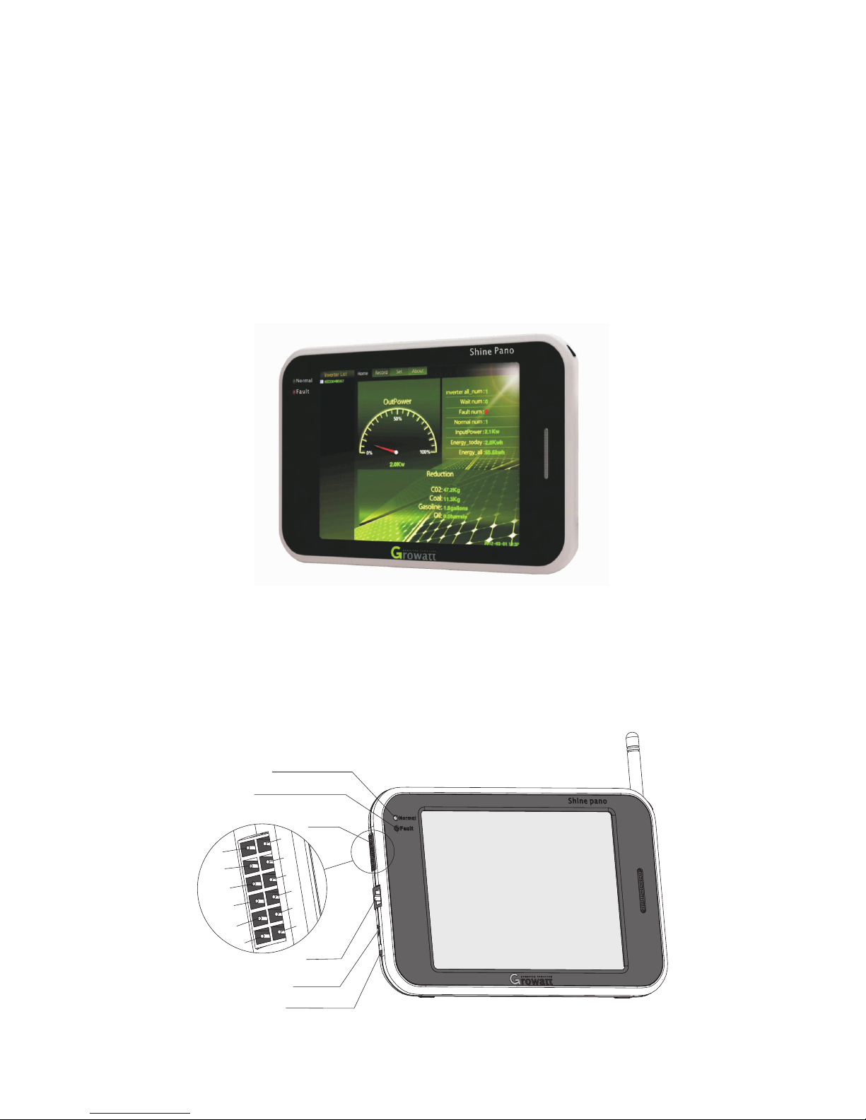
The appearance of Shine Pano is shown below. Friendly user interface are provided
with ture color touch screen containing 800x600 pixels.
1. SW ITCH
4. COM
2. PO WER
1
12
10
6
4
2
11
9
7
5
3
3. LA N
8
8. Fa ult-LED
9. No rmal- LE D
2.1 Device Overview
Page 7
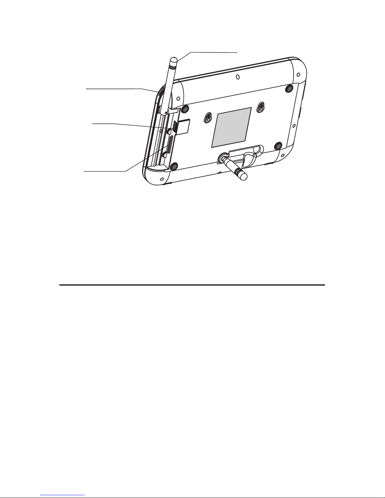
7.A NTENNA
5.USB
10.Touch Pen
6.SD - CARD
2.1.1 Indicator Led
Indicator led can be divided into fault led and normal led.
Fault led indicates fault state, normal led indicates normal state.
There are five different led color combinations which stand for different situations.
Red led
Description
Long lighting
Go out
Go out
Go out
Long lighting
Long lighting
Flashes slowly
Flashed quickly
Long lighting
Go out
Green led
System starting
Searching inverters
Some inverter is standing by
Inverters work normally
Inverters report error or No SD card inserted
4
Page 8
2.2.2 Interface
The description of Shine Pano Interface is listed below.
Label
Function
1
2
3
4
5
6
7
10
Switch
Power
Lan
COM
USB
Sd-Card
Antenna
Touch Pen
Name
Power Switch:Tur n On/Off Shine Pano
Power Line:Connect the power line to charge
RJ45 port:Connect Shine Pano to the local
network or Ether net
As the Figure shows, port 2 and port4 are used
for RS485;Others for active and reactive power
adjustment
Auto-update via USB flash disk
Data storage via SD-CARD
Receive wireless signal
Used for operation on touch screen
5
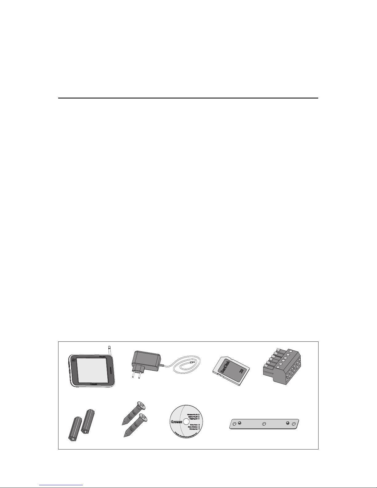
2.2 Unpacking
Shine Pano and accessories can be found as below.
2.2.1 Shine Pano packing list
Page 9
Label
Amount
1
2
3
4
5
6
7
8
Shine Pano
5V Power Adapter
2G SD Card
Terminal Rs485
Plastic Column
M3.5*20 Screw Spike
Shine Pano Instruction Disc
Bracket
Name
1pc
1pc
1pc
1pc
2pcs
2pcs
1pc
1pc
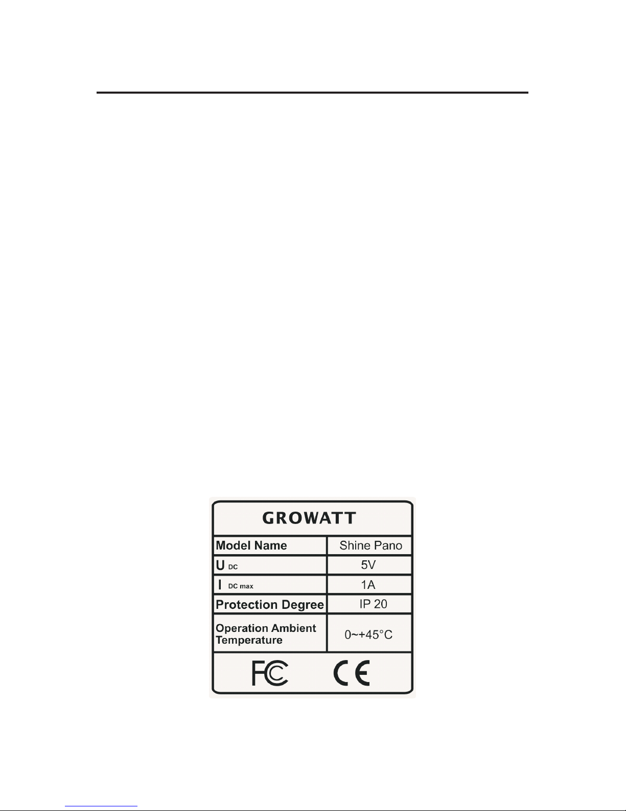
The label is sticked on the back side of the Pano, indicating the type of product, the
voltage and current of the power supply, IP grade, ambient temperature and
certificate informations.
6
2.2.2 Label
Page 10
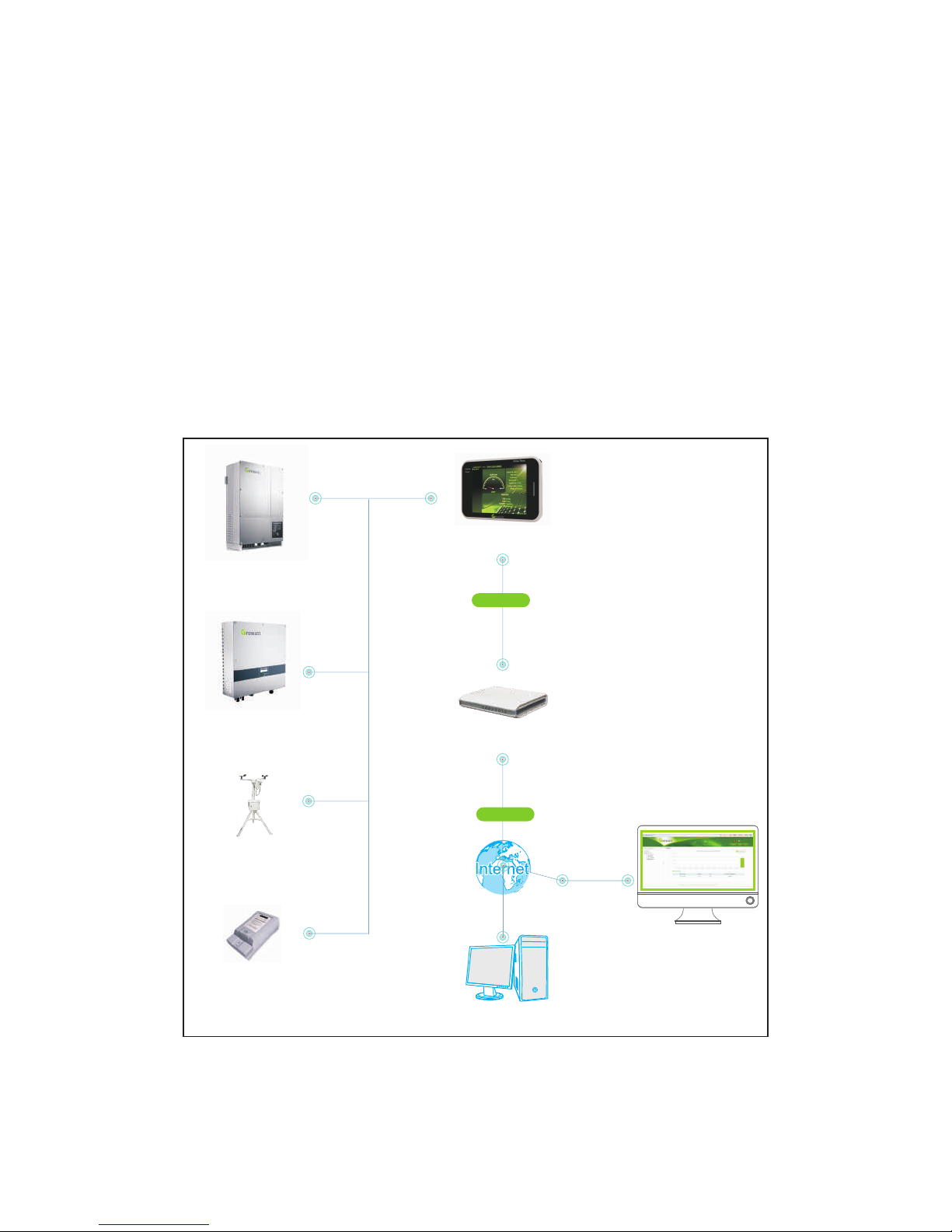
2.3 Introduction of Product Function
Shine Pano is a monitoring device designed and manufactured by Growatt. Shine
Pano could monitor inverters via RS485 and ZigBee wireless module. Besides
inverters, it can also monitor other devices like environment monitor and smart
meter. Pano can correlate with anti-flux device to guarantee there’s no power
sending from PV system to grid. Pano has a touch screen, which can match Shine
Server to set up an Ethernet network system. Schematic diagram is shown as
following figure.
7
Client
Router
Shine Pano
Internet
Ammeter
Environment
Inverter
Inverter
RS 485
RS 485
RS 485
RS 485
Ethernet
Servers
Page 11
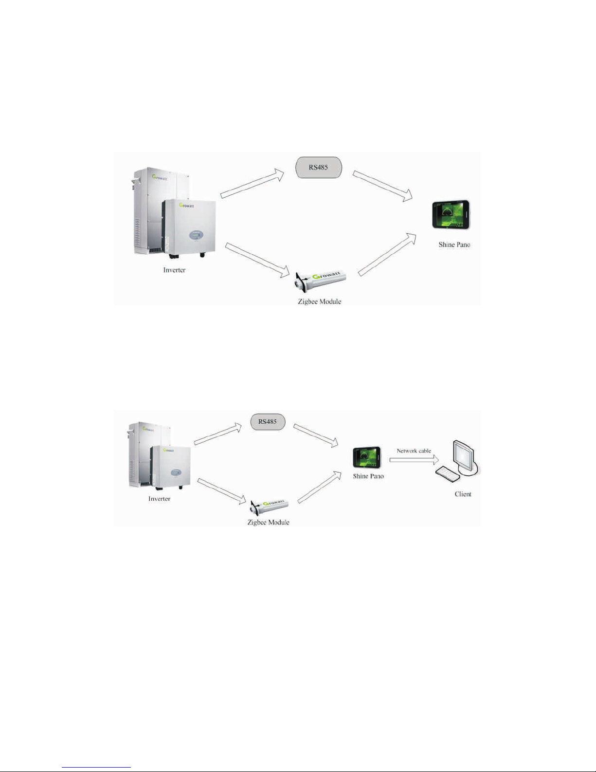
As a terminal display device to show customers about the operation status, Shine
Pano can storage history data in internal memory and SD card. If the total amount of
inverters monitored by Pano is more than 1 piece, the connection mode between
inverters is RS485.
As an intermediate device, Shine Pano collects the data of PV system and sends it to
an upper computer or dedicated server.
For convenience of custom-tailored communication solution and cost control, Shine
Pano provides customers with different kinds of portals.
8
Page 12

The monitoring data of Shine Pano contain two aspects:
1.Operation Data of PV plant
· The total volume of inverters
· The total volume of standing-by inverters
· The total volume of error inverters
· The total volume of normal inverters
· Capacity per day
· Total capacity
· Emission of Co2
2.Data of every inverter
· Operation status
· ID of inverters
· Current power
· Capacity per day
· Total capacity
· Total uptime
· Error message on LCD of each inverter
· Voltage/current/power on DC side
· Voltage/current/power on AC side
· AC frequency
· Communication address of inverters
· Temperature
· Power curve
9
Page 13
3 Product Installation and Connection
3.1 Installation Environmental Conditions
The installation environmental conditions of Shine Pano and requirements
communicating with other devices:
(1) Indoor, temperature 0~45℃ ,humility0~95%,avoiding moisture and direct
sunlight.
(2) Communication distance is 1200m by Rs485.
(3) Communication distance in open space is 300m by Zigbee Module.
(4) The length of cable between router and switchboard should be within 100m.
3.2 Installation Methods of Shine Pano
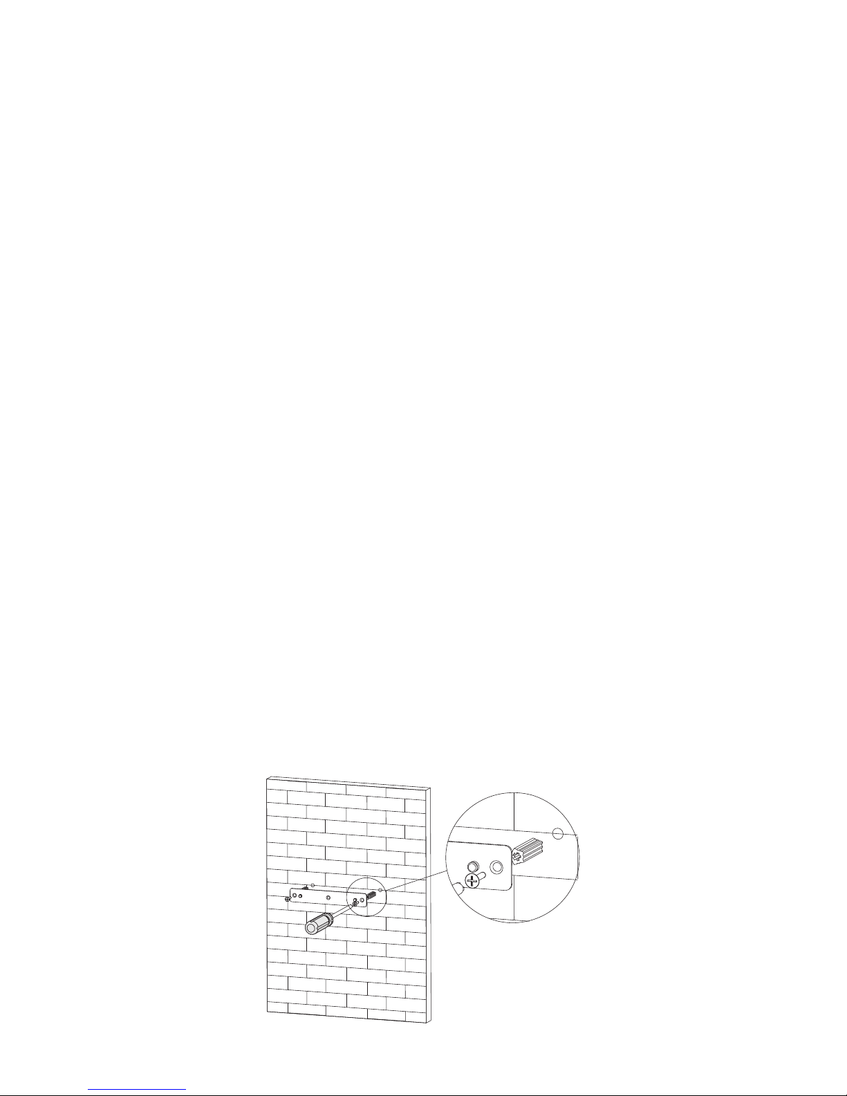
3.2.1 Wall Mounting Method
Installation steps:
(1) Put the mounting rack on vertical plane. There are two screw holes on the rack,
using electric drill (6mm drill) to drill two holes corresponding with the holes on the
rack. Knock the plastic mold sticks into the holes by hammer. Then screw the rack on
the wall.
10
Page 14

(3) Well-installed Shine Pano is shown as following figure.
(4) Connect the portal RS485 of Pano with portal RS485 of inverter (details refer to
chapter 3.3.1 hereinafter) or put ZigBee module into portal RS232 of our inverter
(5) Cable connection (put web cable into LAN portal of Shine Pano)
11
(2) Mount the Shine Pano on the rack.
Page 15
(6) Insert SD card ( Start up the Shine Pano after the action of putting SD card inside,
otherwise SD card cannot be identified)
(7) Connect the Power supply line
(8) Switch on Shine Pano
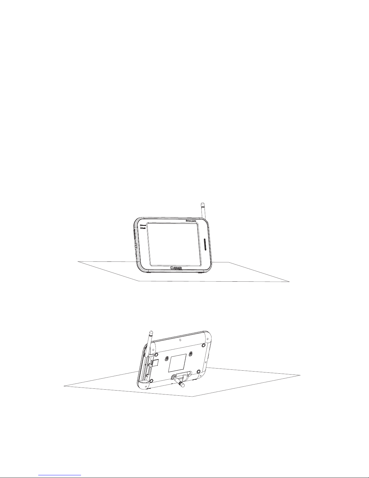
Installation steps:
(1)Take out the rod from the back of Pano, supporting the Pano, and then put it on a level.
3.2.2 Horizontal Placement Method
12
(2) Other steps please refer to steps (4)-(8) of wall mounting method.
Page 16
13
3.3 Connection with PV Devices
Shine Pano can communicate with devices like inverters, environment monitors,
smart meters etc.
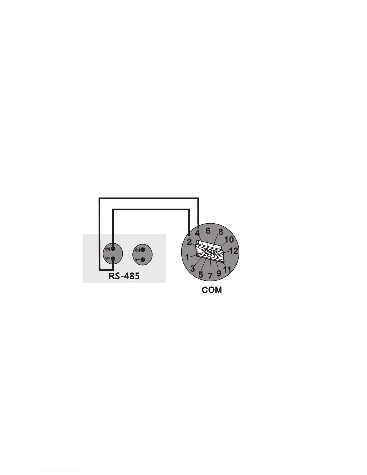
3.3.1 RS485 Wire Connection
1. To set up RS485 wire communication, please notice the identification number of
portal RS485 of inverters. 2# of RS485 corresponds with 2# of Pano COM, 1# of
RS485 corresponds with 4# of Pano COM as following figure.
2. Inverters can connect one by one in series by RS485, and then connect the last
inverter to the Shine Pano.
3. The connection with smart meters and environment monitors is similar with the
way with inverters. To monitor the environment monitors, you can just connect the
environment monitor to the inverter. With regard to the smart meter, you can
connect the communication cable to the COM portal of Pano.
Notice:
ones designated by Growatt. Otherwise, connection could possibly fail.
The manufacturers of environment monitors and smart meters must be the
Shine Pano C OM port
Inverter R S485 port
Note: the position of the nume ral marks may be reversed, please refer to the actual product, and
connect th e Pano and inver ter according to the num eral marks.
Page 17

14
ZigBee connection is a communication method between inverters and Pano by which
we insert the ZigBee Module into inverters. Before setting up the connection, we
need to set the ZigBee ID and Channel. Details please refer to the ZigBee Module
User Manual which attached to the product when purchased.
3.3.2 ZigBee Wireless Conection
3.4 Connection with Network Device
We use network cables to set up the connection between Pano and upper computer.
To get access to Ethernet, please connect the network portal of Pano to the router
and switchboard.
Page 18

4 System Setting
4.1 Shine Pano Setting as a Terminal Display
The system setting interface is below:
15
1. When communicating with RS 485, please set the “Address Range” in “System
Set”, all the inverter address monitored should be within the address range. After
setting the inverter address range, click “OK” on the left and click “Yes” to confirm
the setting.
Page 19

16
If the dialog box below appears, the address setting is successfully finished.
2. When communicating with wireless ZigBee, you have to do the inverter address
setting as before. After address setting, you should set the wireless ID and channel in
“Extra” and finish the related setting. Please reset the wireless module after all the
setting. For more details, please refer to ZigBee Module User Manual.
4.2 Shine Pano Setting as an Intermediate Device
1. When communicating with RS485, please set the Address Range in System Set and
set the inverter address within the address range. Then set the IP address of Shine
Pano, including the Local IP and Server IP or domain name. When the server has both
IP and domain name, the IP access would be prior.
Page 20

17
2. When communicating with wireless ZigBee, please set the Address Range as
before, at the same time, you should set the wireless module ID and channel. After all
the setting, reset the wireless module. Then you can set the IP Address of Shine Pano,
including the Local IP and Server IP or domain name. When the server has both IP and
domain name, the IP access would be prior. Details please refer to ZigBee Module
User Manual.
4.3 Environment Monitor, Smart Meter, Power Reducer Setting
1. Environment monitor setting. Fill in the address of environment monitor in
and choose “ON” in the drop-down menu.
2. Smart meter setting. Fill in the address of smart meter in Addren and choose “ON”
in the drop-down menu.
3. Power reducer setting. You can set “ON” and “OFF” in the drop-down menu of
Power Adjust. When it is “ON”, it means the power reducer is operating, when it is
“OFF”, it means the power reducer is closed. And there is a “Host” and “Slave” in
the second drop-down menu. When it is “Host”, it means Shine Pano is master
machine, when it is “Slave”, it means Shine Pano is slave machine.
After finishing all the settings, click “OK” on the right lower. Then click “Yes” and
get access to the new interface.
Addren
Page 21

5 Guideline on LCD Display
5.1 LCD Touch Screen
The touch screen of Shine Pano is Resistive Touch Screen (RTS), as one of the latest
technologies for HMI; it’s an apparent input system and absolute positioning system.
The touch screen makes it available to operate Shine Pano by touching icons or words
displayed in the screen and get away from mouse and keyboard.
18
5.2 ShinePano Main Interface
Open the main interface of Shine Pano, on left side of the interface it’s the monitored
inverter list, on right side is corresponding monitoring information and data of these
inverters including number of monitored inverter, timely power generation data,
daily power generation data, total power generation data and the reducing of Co2.
Page 22

5.3 Record Interface
1. Click or touch the “Record” on main interface using finger or the stylus to get
access into the “Record” interface.
19
2. Click or touch the word “E_Histogram” shown in above figure then it will prompt
out the drop-down menu. This menu contains submenu shown in following chart.
No.
Description
1
2
3
4
Detail Data
Power Wave
E_Histogram
Error
Options
Detailed data
Power curve
Histogram of Power
Error information
Page 23

20
3. Click or touch the box that shows the word “Daily in Month” and a drop-down
menu will prompt out. Display following information:
· Daily in Month
· Monthly in Year
· Yearly Life time
As shown in following figure, click or touch any option of this drop-down menu can
select the option. You can also select the date by clicking box that shows the word
“2012/10/23”.
As shown in following figure, select Power Wave in the first box, inverter in second
box and T ime of day in third box, and select an appropriate date in fourth box. After
finishing selecting, click “OK” button and then click “Yes” button in the prompt
window and finish the setting. It will display the daily power generation curve.
Page 24

21
Note:
·Detailed power data can only be daily viewed.
·Power and energy curve can be daily, monthly and yearly viewed.
·Error information of inverter can only be monthly viewed.
5.4 Setting Interface
5.4.1 System Set Interface
System setting interface is shown as following figure.
Page 25

22
Normal Set
Remark
Language
Update Time
Protocol
Delay time (s)
Address Range
System Time
Internet_Set
English by default
5 minutes by default
Modbus by default
2 second by default
Address range of inverter
Time of inverter location
Internet setting options
Description
Only English now
Users don’t need to set it
Internet Set
Remark
Local_IP
Local_MAC
Server_IP
Server_URL
IP address of devices
MAC address of devices
IP address of the server
Domain name of the server
Description
Users don’t need to set it
Page 26

5.4.2 Inverter Set Interface
Inverter setting interface is shown as following figure.
In the box after Inverter is inverter serial number that to be set. Information of
inverter setting is shown in following chart.
No.
Description
1
2
3
4
5
6
PV_OnOff
PF_CMD
Active_P_Rate
Reactive_P_Rate
Power_factor
PFModel
Parameter Name
Startup/Shut
down inverter
PF commends
Active power
Reactive power
Power factor
Enable reactive
power function
Remark
To start up or shut down
inverter
Command about power factor
For active power control setting
For reactive power control
setting
For power factor setting
3 options, refer to following
figure
23
Page 27

To set active or reactive power control function, firstly corresponding enable option
must be open.
Introduction to PF Model setting:
· PF_by_Set: Enable power factor settings.
· Inda_Reactive: Enable inductive reactive power control function.
· Capa_Reactive: Enable capable reactive power control function.
5.4.3 Extra Set Interface
Extra setting interface is shown as following figure.
1. Local_ZigBee_set
Local_ZigBee_net_ID: Set the ID of ZigBee, default 6688, range 1000~999
ZigBee_radio_channel: Set the channel of ZigBee, default 18, range 11~25
24
Page 28

2. Environmental monitor
Addren: Set the communication address of ambient sensors, range 1~255
Click “36” using finger or the stylus to select the communication address of ambient
sensor, 36 is default value. Select “ON” or “OFF” to open or close the communication
address of ambient sensors.
3. Ammeter
Addren: Set the communication address of ammeter, range 1~255.
Click “37” using finger or the stylus to select the communication address of ammeter,
37 is default value. Select “ON” or “OFF” to open or close the communication address
of ammeter.
4. Power adjust
Select “ON” or “OFF” to open or close the function of power adjustment.
Select Host or Slave to specify Shine Pano as host or slave devices during power
adjustment.
Once finished all the setting of ammeter, ambient sensor and power adjust, click “OK”
button at bottom and click “Yes” in prompt window then finish setting.
5.5 About Interface
About interface is shown as following figure.
25
Page 29

This interface will display following devices
· Serial number of Shine Pano.
· Model of Shine Pano.
· Software version of Shine Pano.
· Hardware version of Shine Pano
5.6 Operation Introduction to Inverter List
Click any inverter shown in inverter list will turn to interface.
This interface will display following information:
· Running status, ID, software version, communication address and temperature.
· DC voltage, current and power.
· AC voltage, current, power and frequency.
· Timely, daily, total power and power generation time of inverter.
· Error information of inverter.
26
Page 30

6 Network Access
6.1 Access via Integrated Web Server
1. Connect Shine Pano to local network via network cable.
2. Start the web browser, enter 192.169.1.230 in the address bar and press the
ENTER key.
27
3. Click on “Record”, this page is about inverters which are monitored by the Shine
Pano.
Page 31

28
4. Click on “Back home”, return to the main interface. To go to the configuration
page, click on the “Parameter”.
5. Setting parameter
A. Set the address of the Shine Pano
The address setting includes IP address, subnet mask, default gateway. If the first 3
figures of IP address and default gateway are the same, you could only set the IP
address rather than the subnet mask, default gateway or DNS.
Page 32

29
1) You are able to operate the Shine Pano by using integrated web browser in the
local network. Click on “parameter” to go to the setting page.
2) Select “local_ip”, enter the fixed IP number if you want to change the IP address,
for example the default address is 192.168.1.230, and you can change it to
192.168.1.240 referring to following picture.
3) The subnet mask of the Shine Pano and that of the network which Shine Pano
accesses should be same.
4) Set the default gateway of the Shine Pano same as that of the router which Pano
connects to. Please confirm the default gateway is compliant with the network.
5) Set the DNS same as the network that you access.
6) After configuration, click on “save” at the bottom. After setting the IP address
successfully, restart the Shine Pano, then you can get access to the Pano using web
browser by entering the new IP address.
B.
The IP address of the server could be regarded as the IP address of Shine Server which
is one of the products of Growatt. Normally Shine Pano gets access to server
according to the IP address; otherwise it will detect the server according to the
domain name. The default IP address of integrated server in Shine Pano is
192.168.1.74
1) In “parameter” field, select “server_ip”, enter the IP address of Shine Server. For
example change the IP address of server from 192.168.1.74 to 223.4.29.219.
Set the IP address of the server.
Page 33

2) Click on “save”, the configuration has been carried out successfully; Shine Pano
could upload the data to specified server.
C.
according to the specified server IP, when this fails, it will try to connect the Server by
the domain name). The default domain name is “server.growatt.com”, if user
doesn’t want to connect the Shine Pano to the default server, please change the
domain name.
Set the domain name of the server (Shine Pano will try to connect the server
D .
“Addren_start:1,Addren_end: 32”.
S e t t h e i n i t i a l a n d f i n a l a d d re s s . T h e d e f a u l t a d d r e s s v a l u e i s
E. Set the data updating frequency from the drop-down list. The default setting is 2s.
30
Page 34

F. Set system time, select “enable_write”, enter the data and time.
H.
selecting “ON” or “OFF”.
Set environmental monitor, the address is 36. Open or shut down this function by
G.
ZigBee_channel is 11~25.
Set ZigBee parameter, the range of ZigBee_ID is 1000~9999, the range of
I.
or “OFF”.
Set smart meter, the address is 37. Open or shut down this function by selecting “ON”
J.
facto r y s etting , s e lect “Ena b le_Re s et”. Clea r u p t h e re c ord b y s e lecti n g
“Enable_Clear_record”.
System setting. To restart the Shine Pano, select “Enable_Reboot”. To restore
K. After finish the configuration, click on “Save”.
31
Page 35

6.2 Access via the Shine Server
1. Start web browser and enter http://server.growatt.com . If you are the first time to
login, please register in advance.
2. After registration, and fill in the login information.
32
Page 36

3. The main interface is shown below.
4. Regarding to the operation about the Shine Server, please refer to the
corresponding user manual.
6.3 Access via the Shine Station
The monitoring data in the Shine Pano could be viewed via the Shine Station.
6.3.1 Installing the Shine Station
The installation procedure is brief. Just double click the installer, and carry out the
operation according to the prompt.
6.3.2 Logging In
After installation, a shortcut icon of the Shine Station will be set up on the desktop.
Double click the shortcut icon, a new small icon of the Shine Station will appear in
the bottom right corner of the desktop.
33
Page 37

Right click the small icon, select the “Start server”, then the prompt information will
pop up.
Start web browser (Google Chrome is recommended), enter the native IP address and
port number 5678, e.g. the native IP address of the server or computer installed with
Shine Station is 192.168.1.74, then enter 192.168.1.74:5678 or 127.0.0.1:5678 in
the web browser.
The operation of the Shine Station could be carried out after log in. The user name
defaults to admin. And password is 123456.
6.3.3 Starting the Shine Station Monitoring
Click on “Search Device” → select “TCP Setting” from the drop-down list.
34
Page 38

Click on “Start Server”, enable the monitoring service. When the Shine Pano is
connected to the Shine station successfully, the setting status will display as below.
35
Page 39

6.3.4 Checking Up the Data
When Shine Pano connects to the Shine Station well, the plant status could be
viewed by the Shine Station.
36
Page 40

7 Power Management
Shine Pano power management is composed of active power reduction and reactive
power control components. To enable power management, a ripple control receive is
required. When this function is required, user should activate it. The COM ports of
the Shine Pano are shown as below. Pin 1,3,5,7,9,11 are used to connect the ripple
control receiver.
There are 4 power levels, 100%, 60%, 30% and 0%. The connection between ripple
control receiver and Pano is shown as below.
37
1. SWITC H
4. C O M
2. POWER
1
12
10
6
4
2
11
9
7
5
3
3. LAN
8
8. Fault-LED
9. Normal-LED
7.1 Active Power Reduction
Page 41

1
5
3
7
9
10 0%
60 %
30 %
0%
The output power level of inverter depends on the operating relay. The detailed
information is shown as below. Pin 1 is connected to 3.3V dc source.
Pin
Explanation
1
3
5
7
9
3.3V DC source
100% output power
60% output power
30% output power
0% output power
Status
Powering relays
When the relay corresponding to pin
3 actions, the inverter outputs 100%
of nominal power.
When the relay corresponding to pin
5 actions, the inverter outputs 60%
of nominal power.
When the relay corresponding to pin
7 actions, the inverter outputs 30%
of nominal power.
When the relay corresponding to pin
3 actions, the inverter outputs 0% of
nominal power.
7.2 Reactive Power Control
There are 4 power factor levels, 0.99, 0.98, 0.97, 0.95.The connection between
ripple control receiver and Pano is shown as below.
38
Page 42

7
9
11
3
5
0. 95
0. 97
0. 98 0. 99
39
The output reactive power level of inverter depends on the operating relay. The
detailed information is shown as below. Pin 11 is connected to 3.3V dc source.
Pin
Explanation
9
7
5
3
0.99 PF
0.98 PF
0.97 PF
0.95 PF
Status
When the relay corresponding to pin 9 actions,
the power factor of the output power is 0.99
When the relay corresponding to pin 9 actions,
the power factor of the output power is 0.98
When the relay corresponding to pin 7 actions,
the power factor of the output power is 0.97
When the relay corresponding to pin 9 actions,
the power factor of the output power is 0.95
Page 43

7.3 Manage Active and Reactive Power Simultaneously
If active power and reactive power need to be managed at the same time, connect
the Shine Pano with two ripple control receivers as below.
1
5
7
9
11
3
40
7.4 PV Power Station Solution
In PV power station, there are more than one Pano. You can choose one Pano as the
host connecting to the ripple control receiver. The host Pano could send commands
to other Panos (slave Pano) by the local network.
Normally, ripple control receiver would send commands to the host Pano if power
management is required. The host Pano would operate the inverters connected to
itself, meanwhile, it would send commands to salve Panos, which could operate
other inverters.
Page 44

41
Page 45

8 Maintenance
8.1 Shine Pano firmware upgrade
42
1. Get upgrade package from Growatt
2. Copy the RAR archive file to the root directory of USB flash disk.
Page 46

43
3. Select the RAR archive, right click and select Extract here.
Note: You need to have some compressing application like winzip, winRAR, zip7 or any.
Page 47

4. Plug the USB flash disk to the Pano when the Shine Pano is tur ned on. Then the
upgrade is carried out automatically.
5. If the Pano beeps twice, the upgrade is OK. If the Pano beeps 3 times rapidly, the
upgrade is unsuccessful. Plug out the USB flash disk, and try again after 1 mins.
6. The Pano will restart automatically after successful upgrade.
Note: If the Pano beeps 3 times after restarting, this is normal.
7. You can check up the firmware version from the touch screen.
8.2 Factory Default
Note:
1. Create a new folder named “datalogger_Factory_Reset” in the root directory of
USB flash disk.
2. Plug the USB flash disk to the Shine Pano.
3. The Shine Pano will twice, then plug out the USB flash disk.
4. The Pano will restart, and restore factory settings.
A USB flash disk is required.
beep
44
Page 48

8.3 Troubleshooting
Problem
Shine Pano cannot
communicate with
inverters via Rs485
Shine Pano cannot
communicate with
inverters via ZigBee
Shine Pano cannot
connect to the Shine
Server
1)Check the connection between inverter and Shine Pano
is OK, please refer to chapter 3.3.1. 2)Please confirm the
communication addresses don't repeat, and are in the
detecting range of the Shine Pano.
Please confirm the ID channel of ZigBee Module coincide
with that of the Shine Pano. If the communication is not OK
yet, please reconfigure the ZigBee Module referring to
corresponding user manual.
Note: ZigBee Module need to be purchased extra.
1)Make sure the Pano and router are in the same network
segment; 2)Confirm the parameter of the Pano about the
server coincides with the Shine Server, e.g. IP address,
domain name.
Rectification
45
Page 49

9 Technical Data
9.1 Shine Pano
Mechanical data
Width*height*depth
Net weight
240mm* 160mm * 25mm
820g
Environmental conditions
Ambient temperature
Degree of protection
0 ℃… 45℃
IP 20
Mounting location Indoor
Communication
Data displaying
Rs485 communication
Data updating frequency
Wireless communication
Data storage period
System data
Maximum 30 inverters
5min
ZigBee maximum 15 inverters,
More than 5-years-storage capacity
via 2G SD card
Inverter list, real-time power, daily energy
yield, historical record, power histogram etc.
RS 485 communication range
Single inverter data
ZigBee communication range
Grid data
1200m,STP
DC/AC voltage, DC/AC current, DC/AC
power, AC frequency, daily energy yield,
historical power, power graph, power
histogram
300m,obstruction free
Grid voltage, grid frequency
46
Page 50

47
Interface
Language
Display screen
LED indicator
English
800*600TFT, true color touch screen
System operation state indicator
Power supply
Input
Output
100~240V 50/60Hz
5Vdc/2A
Page 51

10 Contact Us
If you have technical problems concerning our products, please contact the Growatt
serviceline.
GROWATT NEW ENERGY
No.28 Guanghui Road, Longteng Community, Shiyan, Baoan District, Shenzhen,
P.R.China.
Growatt Serviceline
Tel: +86 755 27471942
E-mail: service@ginverter.com
Web:www growatt com. .
48
GR - UM - 017 - 00
 Loading...