

Growatt ShineLimit User Manual
Growatt ShineLimit
User manual
For mo re info , pleas e downl oad fro m http: //ser ver.g rowat t.com
+86 75 5 2951 58 88
+86 75 5 2747 21 31
serv ice@g inver ter.c om
www. ginve rter. com
1) Before using the unit, please read this manual carefully.
Otherwise, if you don’t follow the steps described of the
instruction to use and cause any damaged,Growatt has the
right not to service you.
2) All the tasks described in this manual should be performed by
qualified personnel.
3) During installation, please don’t touch any inside part of this
unit besides terminals.
4) All wires connection of unit should be abided by the local
electric safety criterions.
5) If necessary, please contact specified installer
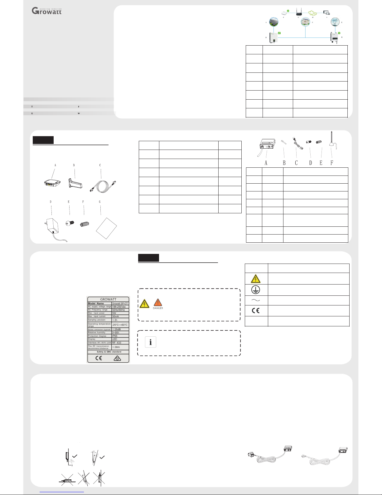
Ite m
Nam e
Des cript ion
A
PV pa nel
Inv erter P V panel
B
Inv erter
PV In verte r with Sh ineRF Stick
C
Loa ds
Use r loads
D
SP- CT
Shi neLim it dete cting m eter
E
Gri d
220 V publi c grid
F
Shi neLan Box
Shi neLim it cont rolle r
G
Rou ter
Unpacking
1.1 Unpacking ShineLink, and check the package
device list:
·Safety precaution
·Product Description
Growatt ShineLimit0 is the zero output control system for
pv plant. It use RF wireless devices to communicate, like
ShineRFStick and SP-CT, control the pv inverter active power
by the power of loads to enable zero output to Grid, and can be
monitored from the net server by RJ45. The System Diagram
as bellow:
Sys tem Dia gram:
Step1 .
Ite m
Nam e
Qua ntity
A
Shi neLan Box
1
B
Shi neRFSt ick
1CNet work
1DPowe r adapt er
1
E
Fix ing scr ews
4
F
Wall p lasti c posts
2
G
Use r manua l
1
1.2 Unpacking SP-CT, and check the package device
list:
Ite m
A
B
C
D
E
F
--
--
Des cript ion
Gro wat t SP-CT
Ant enna
Sen sor (wa ter-pr oof t ermin al)
M5* 30 pan he ad scre w
Exp ansio n screw
W
Suc ker ant enna th is is for S P
(St orage m achin e)
arr anty ca rd
Man ual
Qua ntity
1
1
1
2
2
1
1
1
1.3 SP-CT SE
1.3.1 Nameplate description
The re is som e essen tial in forma tion su ch as pro duct mo del,
spe cific ation s and app rova
l on th e Namep late in t he
rea r of SP-C T:
Installation
Step2 .
2.1 General precautions
A. Sa fety me asure s
·Qua lifie d perso nnel ca n opera te only
·The kid s, t he di sable , non- pro fes siona l are
not all owe d to clo se.
SP- CT Hig h vol tage d ang er!
SP- CT Grou nd wire con nec tion
Ens ure th e SP- CT gro und wi re is pro perly
ear thed
Sym bo l
Des cr ipt ion
Ris k of elec tric sh ock!
Gro und p oint
Alt erna tin g cur rent
CE Ma rk, whi ch mean s it sati sfies C E crite rion
RCM M ark, wh ich mea ns it sat isfie s RCM cri terio n.
B. Sy mbol us ed of SP- CT
C. Devi ce inst all pla ce plea se refe r to the sy stem Di agram
abo ve.Ab out the d istan ce betw een the S hineL anBox w ith the
Shi neRFS tick an d SP-CT , the max imum li near di stanc e is
200 m if ther e is no obs truct ions be tween t hen; th e maxim um
dis tance i s 50m if th ere is on e wall be tween t hen;
the m aximu m dista nce is 20 m if ther e are two w alls be tween
the n.
2.2 Install SP-CT
2.2.1 Basic requirements of mounting
A
tim e. ( refe r to the ch apter 3 .3 to kno w the pre cise we ight)
B Mou nt on whe re has en ough sp ace for S P-CT ( re fer to th e chapt er 3.3) .
C Do no t mount o n flamm able co nstru ction m ateri als .
D Des igned w ith IP6 5 degre e for ind oor or ou tdoor a pplic ation s .
E Amb ient hu midit y range : 0~95% .
F Amb ient te mpera ture ra nge: -2 5℃~60 ℃.
G Ve rtica lly in stall ation or til t angl e 15-d gress insta llati on is o k, as the
cha rt 5.1 .
Mou nt on soli d sur face and ca n acc ommod ate w eight of S P-CT long
.
H To m ake sur e opera te and m ainta in avai lable the uni t, plea se lea ve
eno ugh spa ce for S P-CT.
2.3 Installation guide
2.3 Installation layout.1
2.3 Mounting.2
1). M ark loc ation s of the ho le of SP- CT.
2). I nsert 2 e xpans ion scr ews in th e holes .
3). S crew 2 sc rews( M 5) firm ly.
4). P lace th e SP-CT o n the 2 scr ews .
Ins talla tion la yout of s torag e energ y syste m with SP -CT sho uld
be as f ollow ing fea ture sh ows .
Not e: The re comme nd dist ance be tween s tored -ener gy mach ine
and S P-CT is l ess tha n 50 m.
I
fun ction .
Do n ot inst all whe re is ne ar to Ra dio or ma chine which h as wire less
J Do n ot inst all the place w here th e chil dren ca n reach .
2.4 Wires connection
2.4 AC auxiliary power wires connection.1
Pre parat ion:
(1) E nsure t he grid v oltag e is 230V AC or 240 VAC, fr equen cy
is 50 /60Hz s ingle p hase.
(2) C onnec tion mo de:
a) Ty pe I:Co nnect t he AC ter minal o f SP-CT t o the AC br eaker
of po wer dis tribu tion ca binet .
b) Ty pe II:P ress th e AC term inal (B ritis h stand ard) of S P-CT
on th e nearb y socke t. Beca use of in stall ation o utsid e,
the s ocket s hould b e water -proo f.
Cau tion: Ensur e the uti lity ph ase of SP -CT pos ition i s same
wit h store d-ene rgy mac hine an d PV inve rter ph ase pos ition .
Typ e I
Typ I I
Not e: Type I I insta llati on is mai nly sui table f or Brit ish
sta ndard a rea.
Gre en indi cator s olid on
Gre en indi cator f lash
Red i ndica tor sol id on
Wor king no rmal
In pa ir stat us
Fau lt e.g L an d N conne cted
rev ersel y or GND wi re unco nnect ed
2.4 Installation of sensor.2
1) Pr ess one s ide of se nsor te rmina l on the “S ensor i nput
ter minal ” and mak e sure fi xed fir mly.
Ref er to Cha rt 5.6
2) Pl ease st rictl y follo w the ins truct ion ste ps to ins tall th e other
sid e of sens or, Ref er to bel ow char t.
As pi cture d above , uncov er the se nsor. P lease p lace th e L line
on th e posit ion wit h arrow a nd then f asten i t.
Not e:
a Thi s arrow i ndica tes dir ectio n of sens or.
b The d irect ion of th e arrow ( from K to L ) denot es to the
dir ectio n from th e Load to t he grid .
2.4 Install antenna of SP-CT.3
Scr ew the An tenna t ightl y to ante nna ter minal o f SP-CT a s
sho wn belo w.
SP- CT shou ld be gro unded r eliab ly. The g round w ire of SP -CT
is co nnect ed to its s hell so m ake sur e the AC te rmina l
(L /N / GND) co nnect ed firm ly ( L/N/ GND).
Ref er to cha rt 5.9.
2.4 Ground .4
2.5 Install ShineRFStick
A If the RS-232 port of the inverter likes the
specification A as below, please turn on pin 1 of the
DIP switch, then plug the Growatt ShineRFStick to
the inverter directly via the RS-232 port and lock the
screws;
B If the RS-232 port of the inverter likes the
specification B as below, please poke the rubber plug
in the waterproof cushion of the Growatt
ShineRFStick, then plug the ShineRFStick to the
inverter via the RS-232 port and lock the screws.
Take the waterproof plate down from RS-232 port of
the inverter
ShineRFStick Electrical Connection
C Power on the inverter, observe the blue led in the
ShineRFStick, if the led on and then turn to flash, it
means ok, otherwise means you should check the
installation.
Blue LED status:
Solid on: device is initializing
Solid off: no device found on RS232 port
Flashing fast (change every 0.2s): Found device on
RS232 port
Flashing slow (change every 1s): network
communication normally
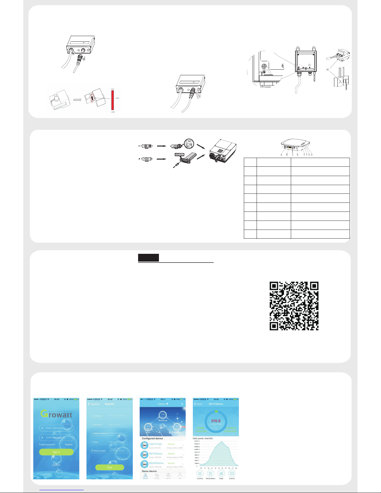
2.6 Install ShineLanBox
Ite m
Nam e
Des cript ion
A
Powe r input
Con nect to t he powe r adapt er
B
RS 48 5
Res erv ed
C
RJ 4 5
Con nect to t he netw ork
D
Key
Fun ction k ey
E
Con figur ation L ED
Con figur ation t he devi ce
F
Dev ice LED
Dev ice num ber con necte d
G
Net work LE D
Con necti ng the ne twork
H
Powe r LED
Con necti ng the po wer
Connect the RJ45 interface of the ShineLanBox to the
router ,then plug in the power adapter to power on the
ShineLanBox,please open the DHCP of Youter.
After power on, the Power LED on, Network LED
flashing, then the ShineLanBox start to search the RF
device and connect to the server. Network LED on
means connect to the server ok, device LED flashing
means devices connect ok. If there are more than one
RF device, please note the device LED continuous
flashing times, it means the connected devices number.
Aft er inst all and p ower on t he Shin eLimi t, it wil l start s ystem
zer o expor t funct ion. If w ant to te st the fu nctio n, plea se
inc rease o r decre ase you h ome loa ds powe r, chec k the inv erter
out put pow er and th e grid po wer on th e serve r web or ph one app .
Use ShineLimit
Step3 .
Note:
1.Power LED : connecting the power
2.Network LED : connecting the network
3.Device LED the number of the LED continuous
flashing means the device number connected to the
ShineLanBox
4.Configuration LED flashing when
configuration , if successful , the LED will be off.
:
:
NOT E: 1.Be s ure to in stall t he late st vers ion of th e softw are;
2.F or more d etail s, plea se refe r to the co ntent o n
htt p://s erver .grow att.c om .
【And roid& 】iOS
3.1 Use the zero export function
3.2 Use ShineLink monitoring
Sea rch “Sh inePh one” in g oogle p lay or ap p store , or scan t he
pic ture be low, do wnloa d and ins tall th e app.
1.R un Shin ePhon e, plea se regi ster a ne w user if i s the fir st time .
Whe n enter ing SN ,P lease e nter th e Shine LanBo x SN , not
the S hineR FStic k SN.
2.I nput th e user na me and pa sswor d to log in .
3.I nto the d evice p age, ch eck the d evice n umber c onfig ured
and t he stat us.
4.P ut the de vice li st to the d etail p age, ch eck the d evice
par amete rs.
A.Pressing the button of the ShineLanBox for more
than 6 seconds until the four LED flash will clear
the configuration information .
B.if clear the configuration information or change the
device, should add and configure the device, short
press the button of and ShineLanBox, then short
press the button of the the ShineRFStick or SP-CT ,
the devices entering the configuration mode, if
successful, the configuration LED of the
ShineLanBox will be off ,and the blue LED of the
ShineRFStick will flash slowly.
Append information
 Loading...