

Page 1

Growatt PCS500
Bidirectional batte ry Inverter User Manual
GR- UM-05 3-A-0 1
GROWATT NEW ENERGY TECHNOLOGY Co.,LTD
+ 86 755 2747 1900
+ 86 755 2747 2131
info@ginverter.com
www.ginverter.com
T
F
E
W
No. 28 Gu angmi ng Road , Shiya n, Baoa n Distr ict,
She nzhen , P.R. Ch ina
Page 2

About this Manual
Safety instructions
Product Description
Contents
1
2
3
1.1 C onten ts
1.2 Tar get rea ders
1.3 H ow to use t his Man ual
1.4 S ymbol s expla natio n
2.1 I nstal latio n
2.2 O perat or
2.3 I nspec tion an d stora ge
2.4 Tr ansp orta tion
2.5 I nstal latio n
2.6 R epair a nd main tenan ce
2.7 I nvert er EMC an d noise l evel
2.8 I mport ant not e
3.1 E nergy S torag e syste m
3.2 C ircui t diag ram of the in vert er
3.3 T he layo ut of the m ain com ponen ts
3.4 O perat ion mod e
3.5 B atter y setti ng
3.6 P rotec tion
3.7 S torag e
3.8 D imens ion
3.9 P ackag ing inf ormat ion
GUI instruction
6
Pilot operation
5.2 I nspec tion
5.4 P ilot op erati on comp letio n
5.3 P ower on s teps
5.1 R eleva nt requ irem ents
5
5.5 P ower of f step s
6.1 L CD disp lay scr een in trod ucti on
6.2 L CD oper ation
6.3 L CD disp lay inf ormat ion sch edu le
Routine maintenance
7
7.1 R eplac ing the d ust scr een
7.2 R egula r maint enanc e
Products installation
4
4.2 Too ls and sp are par ts req uire d for
who le mach ine ins talla tion
4.4 E lectr ical in stall ation
4.3 M echan ical in stall ation
4.1 I nstal latio n condi tion re quir emen ts
4.5 C ommun icati on
4.6 I nstal latio n inspe ction
7.3 W aste d ispo sal
Appendix
8
8.1 S pecif icati on
8.2 G rowat t Fact ory warra nty
8.3 C ontac t
Page 3
1 About this Manual
Thi s chapter de scri bes th e con tent s of thi s man ual, t arge t read er, and s afet y symbols ,
can h elp use rs to hav e a bette r under stand ing of th e man ual.
1.1. Contents
Thi s m anua l appl ies to Grow att PCS500 Bidi rect iona l batt ery inv erte r, t he manu al
con tains :
saf ety in stru ctio n
Pro duct desc ript ion
The rol e inver ter play s in th e energ y st orag e sy stem and str uctu re, prin cipl e,
pro tect ion, oper atio n mode , stor age and p ackag e size of t he Grow att PC S500.
Ins talla tion
Inv erter i nstalla tion c ondi tion s, tools, a nd the i nver ter me chan ical and electr ical
ins talla tion, t he comm unica tion co nnect ion and i nsp ecti on.
Com missi oning
GUI (Grap hic Us er Int erface) i nstr uction
Rou tine m aint enan ce
Dai ly m aint enance of the inve rter, the replacem ent of s ome spar e p arts and wast e
dis posal i nstru ction .
App endix
2
Att entio n that n eeds to be paid wh en op erat ing and mai ntai ning Grow att PC S50 0.
Ins pecti on bef ore co mmis sioning a nd pro cedure to t urn o n/of f inverte r.
Inf ormat ion di spla yed on the inver ter LC D tou ch-s cree n and s etti ng in stru ctio n.
Techn ical d ata, w arranty p olic y and c ontact in form ation.
1.2. Target reade rs
1) O nly pr ofes sional el ectr icians or p rofes sion ally qual ifie d per sonn el ca n
tra nspor t or ins tall this p rodu ct.
2)T he ope rato r should be full y fami liar with t he str uctu re and work ing pr incip le of
the enti re Ene rgy S tora ge system ;
3)T he ope rato r should be full y fami liar with t his ma nual ;
4)T he ope rato r should be full y fami liar with t he loc al sta ndards of t he pro ject.
Qua lific ation
1.3. How to use this Manual
Rea d this manua l befo re ins tall atio n of th e Growatt PC S500 . Stor e this m anual whe re
acc essib le at all t imes.
The c onte nts of th is manu al wil l be per iodi cally upda ted or re vised if nec essa ry.
How ever d iscre panc ies cann ot be excl uded. Pl ease refe r to t he pr oduc t or down load
the l atest v ersio n of this m anual o n www.gr owat t.com.
1.4. Symbols explanation
In o rder to ensure t he pe rson al an d propert y saf ety of the u ser d urin g ins tall ation, or
opt imall y eff icient use of this prod uct, symb ols are used high ligh t t he i nfor mation.
The foll owin g symbol s may be us ed in thi s ma nual , please read care fully, in order to
mak e bette r use of th is manu al.
DANGER
Cautio n, ris k of danger
DAN GER i ndic ates a h azar d wi th a high level o f ri sk w hich , if not avoi ded, will
res ult in d eath or ser ious i njur y.
CAUTIO N
CAU TION indi cate s th ere i s po tent ial risk , if not avoi ded, could
res ult in e quipmen t malf unct ion an d prope rty da mage.
1
Page 4
4
WAR NING
Cautio n,ri sk of elect ric shock
WAR NING
Cautio n, ris k of fire haz ard
PE TERMINAL
Protec tive c onducto r termina l
WAR NING
Risk of el ectr ic shock, E nergy sto rage t imed disc harg e.
3
Whe n ba tter y ba nk conn ecti ng poin t ar e ex posed, ther e wi ll be D C volta ge i n
the equipme nt DC side ; and when outp ut breake r is o n, th ere is a pot ential risk
of el ectri c shock .
Sui table for mountin g on concrete or other non-co mbus tibl e
sur face on ly.
The inver ter has to be fi rmly gr ound ed to ensu re the saf ety of
per sonne l.
Ele ctric al shock dang er e xist s in th e ca paci tor; th e co ver shall be
mov ed at lea st 5 minu tes lat er afte r all pow ers are d isco nnected .
Safety instructions 2
Inv erter i nsta llat ion an d serv ice per sonne l must be trained an d fami liar w ith the
gen eral safety requi reme nt w hen working on e lect rica l e quip ment . In stall ation and
ser vice per sonn el shou ld also be famili ar with the l ocal law s and reg ulat ions an d
saf ety req uire ment s.
> Read this ma nual ca reful ly befo re oper ation. The eq uipm ent will not be und er
war ranty i f faili ng to ope rate ac cordi ng to th is manual .
> Ope ratio n on the in verte r must be f or qual ified e lectr ica l tech nici an onl y.
> When inv erte r o pera ting , don’ t t ouch any ele ctri cal part s exce pt for the tou chscr een.
> All e lectr ical op erati on must c omply w ith loc al el ectr ical o pera tion stan dard s.
> War rant y serv ice fo r the inv erter d oes not c ontai n modul e maint enanc e.
> Perm issi on f rom the loca l ut ilit y c ompa ny i s re quire d before install ing the Energy
Sto rage sy stem an d only pr ofes sional pe rson nel ar e qual ifie d for the ope rati on.
2.1. Installation
Pro per insta llat ion re quires fo llow ing al l the i nstr uctio ns in th e user manu al involv ing
tra nspor tatio n, m ount ing, wi ring and commis sion ing. Gro watt do es not co ver
war ranty f or the in verte r damag e due to fa iling t o use it pr oper ly.
2.2. Operator
Inv erter i nsta llat ion an d serv ice per sonne l must be trained an d fami liar with the
gen eral safety requi reme nt w hen working on e lect rica l e quip ment . Insta llat ion and
ser vice per sonn el shou ld also be fa mili ar with the l ocal law s and reg ulat ions an d
saf ety req uire ment s.
2.3. Inspection and storage
The i nverter shoul d be care fully checked b efore signing th e docu ment f rom the
tra nspor tatio n comp any. Ch eck t he re ceiv ed it ems a gain st de live ry no te, a nd if there
is an y de fect o r damage , im medi atel y no tify t he t rans port ation compa ny. If
nec essar y, you c an see k help from Gr owat t Custome r Serv ice de part ment.
Page 5

5
6
CAUTIO N
Gro watt PCS5 00 can only be s tore d wh en i t is st oppe d an d all
the do ors a re cl osed in a dry roo m to p rote ct th e int ern al
cir cuit s against d ust an d mois ture .
2.4 . Transportat ion
Tran spor tati on s houl d follow th e transp orta tion me thods d escr ibed in the us er
man ual. The inv erte r's weig ht and cent er of grav ity shou ld be take n i nto account
dur ing tra nspor tatio n. The ce nter of g ravit y is mark ed on the b ox.
DANGER
Dur ing tra nsporta tion , lift ing eq uipm ent and p erso nnel mu st be
qu ali fie d. Th e i nve rte r s hou ld b e p lace d ve rti cal ly an d t he
inc linat ion cann ot be more tha n 10 degr ees. It is not al lowe d to
pla ce the i nver ter u psid e down or transp ort in a hori zont al po siti on.
Inc orrec t l ifti ng an d t rans port ation c an l ead t o s erio us in jury,
pro pert y loss and da mage t o the in vert er.
Cautio n, ris k of danger
2.5 . Installation
The prote ctio n le vel o f the inve rter is IP 20, w hich is desig ned f or in door ins tall atio n.
Ple ase ref er to ch apter 4 for i nsta llat ion in struc tion.
The in stal lati on lo cati on mus t be dr y, includi ng no e xpec ted c onde nsation . The
inv erter i s only fo r use in a cl osed el ectri cal ope ratin g area .
Cautio n, ris k of fire haz ard
WAR NING
Sui table f or m ount ing on co ncret e or other no n-combu stib le
sur face on ly.
Rep air a nd m aint enan ce c an o nly be ca rried ou t af ter disc onne cting th e DC and A C
for a t least 5 m inute s.
Onl y profe ssio nal techn ical p erso nnel a re qual ifie d for the ope rati on.
Mai ntena nce an d modi ficatio n
Onl y perso nnel wit h Growatt auth oriz atio n are qual ifie d for the main tena nce and
mod ifica tion. And t o ens ure perso nal safet y, use o rigi nal a cces sori es pr ovid ed by the
man ufact urer only. Othe rwis e, e lect rica l sa fety and E MC m ight not c ompl y wi th the
req uire d stan dard .
Fun ction and sa fety para mete rs
Don 't cha nge th e par amet ers o f the i nver ter wi thout auth oriz ation fro m the l ocal
uti lity a nd Gro watt New En ergy Co., L td. O ther wise , it mi ght l ead to inju ry or
equ ipmen t dama ge and the wa rranty of t he inv erte r will be voided .
Risk of el ectr ic shock, E nergy sto rage t imed disc harg e.
WAR NING
Ele ctric al shoc k dang er exi sts in the cap acitor; t he cov er
sha ll be move d at leas t 5 minutes late r af ter all powe rs are
dis conne cted.
2.7 . Inverter EMC and noise level
Ele ctrom agne tic c ompa tibilit y (EMC ) is the req uire ment for el ectrica l equi pment that
it ca n oper ate no rmal ly in the e lect roma gnet ic env iron ment a nd doe s not cau se
una ccept able en viron ment al impact i tsel f.
Dis conne cting swit ches
Dis conne ct DC sw itch an d AC sw itch , an d mak e su re th e inv erter wi ll not be
con necte d acci dent ally. E nsur e the inver ter is tota lly di sconnec ted wi th no v olta ge by
tes ting with a mul ti-m eter. A ltho ugh the DC an d AC switc h has been dis connect ed,
the re is still vo ltage in some compo nents , for example c apacito rs. Henc e, t he re pair
or mainte nanc e ope ratio n can on ly be pr ocee ded at le ast 5 mi nutes af ter t he
dis conne ction .
2.6 Repair and maintenance
Page 6
8
7
Ant i-int erfer ence property f rom in ter nal compo nent s.
Ant i-int erfer ence property f rom ou tside.
Ele ctrom agne tic e miss ion i mpac t on th e envi ronme nt
Inv erter may gene rate some no ise and elec trom agne tic radi atio n du ring op erat ion.
Acc ordin g to EMC emi ssio n and nois e level , i nverter sh ould be used in industri al
env ironm ents . Hence, al l pers onne l shou ld not st ay long n ear the i nvert er.
2.8 . Important note
Inform atio n
Ite m 1: Sta tic e lect rici ty ca n caus e dam age to the in verter
Ele ctros tati c dis char ge ma y caus e unrecov erab le damage t o inv erte r interna l
com ponen ts!
Whe n oper atin g the i nver ter, op erat or mu st com ply wi th ant i-stati c prot ecti on
nor ms!
Ite m 2: Res tric tion
The inve rter cann ot be d irectly us ed to c onne ct th e life supp ort e quip ment
and medi cal equip ment !
Ite m 3: Pre caut ions
Mak e sure i nsta llat ion t ools o r oth er unnece ssar y items are n ot le ft ins ide t he
inv erter befo re sta rting up.
Ite m 4: Mai nten ance noti ce
Mai ntena nce ca n only be car ried out af ter th e inve rter tota lly d isch arge d.
Product description 3
Gro watt PCS5 00 bidirec tional ba tter y inv erte r is de sign ed fo r energy st orag e sys tem,
it c onve rts DC curr ent ge nerated b y bat tery b ank i nto AC curr ent an d fee d it in to the
loa d/gri d, als o it ca n take powe r from s olar i nver ter or grid to cha rge b atte ry.
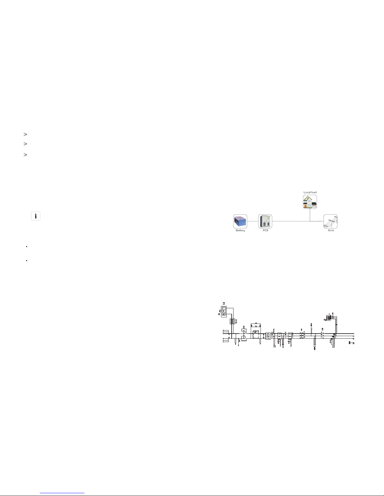
3.1 Energy Storage system
Str uctur e of a ty pical ene rgy s tora ge system i s sho wn as below
Fig ure 3- 1 Gri d-co nnec ted e nerg y sto rage s yste m
Gro watt P CS50 0 bidi rect iona l batt ery in vert er con verts DC cur rent g ener ated b y
bat tery i nto A C cur rent . The n the AC cu rren t is f ilte red i nto s ine w ave e lect rici ty an d
fed i nto th e gr id t hrou gh a m ediu m-volta ge i sola ting t rans form er. I t ca n al so
con verts g rid pow er to DC to c harge b atter y. The c ircu it dia gram i s as below:
3.2 Circuit diagram of the inverter
Fig ure 3-2-1 Gr owat t PCS500 ci rcui t diagram
AC output
Load Connect
DC Input
3继电器
2电阻
Page 7
9
10
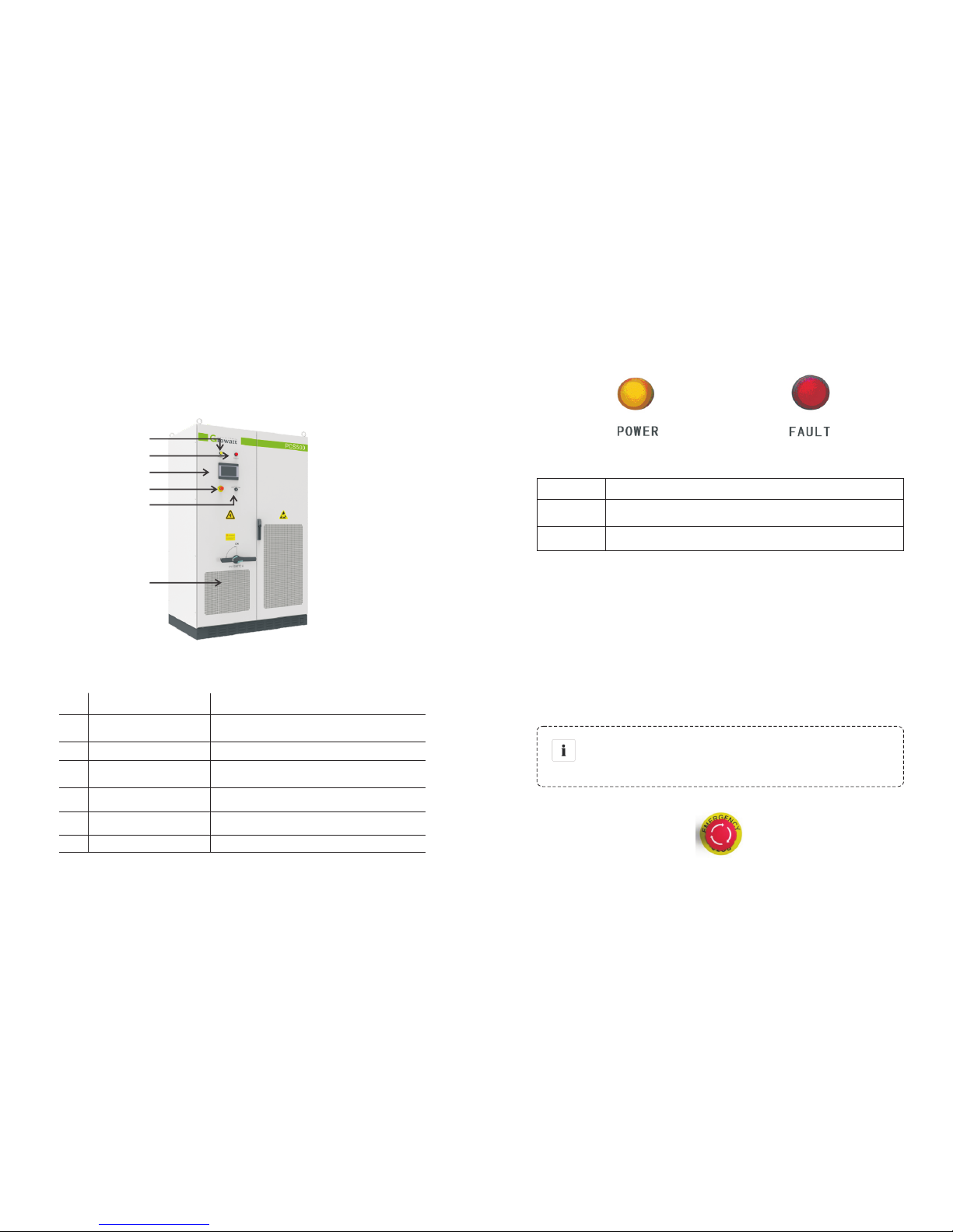
3.3 The layout of the main components
3.3.1 Externa l com pon ent s
Ext erna l main comp onents include : LED i ndic ator, LCD touc h s creen an d s tart -sto p
kno b, emer gency s top but ton.
Fig ure 3-3-1- 1 Inve rter appe aran ce
No. Nam e Des cripi tion
1
Pow er ind icato r Whe n powe r supp ly is no rmal, t he ind icato r disp lays
yel low.
2
Inv erter malfu nctio n indi cator Wh en inve rter i s faul ty, the in dicat or dis plays red.
3
tou ch Scre en LCD
Ope ratio n info rmati on dis play, re ceive contr ol
com mand a nd par amete rs set ting
4
Off -on kn ob
onl y cont rol the grid- side s witch , and do es not
con trol th e DC-s ide sw itch
5
Eme rgenc y STOP
Shu t down t he inve rter w hen pre ssed d own
6
Dus t scree n pre vent d ust fro m enter ing in to the i nvert er
Fig ure 3-3-1 Pa rt descri ptio n
The re are two LED ind icat ors on the inv erte r whic h is used to dis play the cu rren t
sta tus of th e inver ter.
Fig ure 3-3-1- 2 LED indic ator s
LED Des cript ion
POW ER
The indi cato r lig hts wh en po wer suppl y to th e inve rter is nor mal.
FAULT
The indi cato r lig hts wh en po wer suppl y to th e inve rter is nor mal.
Fig ure 3-3-2 LE D status
Ind icato r
AC swit ch is used to c onne ct or dis conn ect the i nver ter a nd u tili ty gr id. DC sw itch is
use d to conne ct or disc onnect t he in vert er a nd DC modu les. If the AC s witc h is u sed
in the case of l oad, the i nverter componen ts w ill be expos ed t o co nsid erab le s tres s.
Fre quen t use of the AC s witc h will l ead to d amage o f the inv erter.
CAUTIO N
The em ergency st op butt on is only us ed in case of emerge ncy,
suc h as: ser ious fa ilure i n the gr id, fire, et c.
Fig ure 3-3-1- 3 Emer gency STO P
AC/ DC mai n swit ch
Eme rgenc y STOP
6
3
1
2
4
5
Page 8

11
12
The emer gency stop but ton i mmediat ely d isco nnec ts th e inv erte r fro m bot h grid and
bat tery, whi ch ensu re the safety of th e inverter. By pre ssin g the eme rgen cy sto p
but ton, the device will be l ocke d in the "off " po siti on. Only rele ase the emergenc y
sto p b utto n b y rota ting it clockwi se and clo sing AC, DC breaker, can the inv erte r
res ume wo rking nor mall y.
Fig ure 3-3-1- 4 Off- on knob
It displa ys th e in vert er’s opera ting pa rame ters, po wer gen eration , a nd f ault y
inf ormat ion rec ord. P leas e refe r to Sec tion 6, for d etai ls.
Off -on k nob
It i s used to sta rt or s top t he inv erter.
Touc h scr een
3.4.1 ON-grid charge and discharge mode
3.4. Operation mode
The re are sever al ope ration mo des o f the inver ter.
CAUTIO N
Whe n the a mbie nt te mper atur e is t oo high, it is no rmal the i nver ter
red uces t he output p ower. Ho wever, if thi s freq uent ly happen s,
che ck the coo ling surfac e of the inv erte r or plac e the inverte r in
bet ter ve ntil atio n con diti ons pl ace. I f the inver ter fa n is di rty, pl ease
cle an th e fan , i f there i s p roble m wi th th e in vert er i nter nal
ele ctric al, ple ase see k help fr om pro fess iona l servi ces.
3.4.3 Fault mode
Whe n th e DC p ower sys tem fail s, the inverter wil l i mmed iate ly disc onne ct the AC
con tacto r and en ters into the fault m ode, so a s t o en sure the safe ty of t he s ystem.
Inv erter cont inuousl y mo nito rs f ault st atus and will not ente r ch arge and di scha rge
mod e until t he faul t is elim inate d.
3.4.4 Permanent fault mode
Whe n the DC po wer s yste m is in se riou s fai lure , the inv erte r will im medi atel y
dis conne ct the AC contact or and ente rs into th e Perm anen t faul t mode , so as to
ens ure the safety of t he syst em. For exam ple: inv erte r m odul e f ailu re e tc. please
con tact your loca l d eale r or Gr owat t directly when inv erte r enter s pe rmanent faul t
mod e, repa irme n on site is no t allo wed wi thou t autho rizat ion of Gr owat t.
Wor king p roce dure o f PCS5 00 at on-gr id cha rge an d dischar ge mod e:
1) PC S500 co nnect ed to bat tery on t he DC sid e, and gr id on the A C sid e;
2) Cl ose the a c/dc ci rcuit b reak er and s tart -stop k nob, PC S500 en ter wai ting st atus;
3) Start PCS 500 via th e lcd, ma chin e enter self -che ckin g, after the mee t on-grid
con ditio ns, the e nergy s torag e contr olle r will run in " on-g rid ch arge “mode .
4) C lick the "s witc h" but ton on the screen. You ca n com plet e the b atte ry ch arge and
dis charg e state tran siti ons. Charge curr ent and disc harge power c an b e se t(defau lt
20A c harge , full po wer dis charg e).
3.4.2 Off-grid c har ge an d dis cha rge m ode
At off- grid mod e, PCS5 00 can work aut omat ical ly, the inverter will sense the load
pow er and ad just it s outpu t autom atica lly :
1) P CS50 0 con nected to battery on the DC si de, a nd lo ad eq uipm ent o n the AC si de,
mak e sure gr id is no t connect ed;
2) Cl ose the A C/DC ci rcuit b reak er and s tart -stop k nob, PC S500 en ter wai ting st atus;
3) S tart PCS5 00 vi a the LCD, inver ter start s sel f-ch eck, when sel f-ch eck f inished and
mee t worki ng requ irem ent, i nver ter con nects t o local l oad.
4) in verte r sense s load po wer and a djust i ts ou tput t o supp ly loc al load equ ipme nt.
Page 9

13
14
3.5 Battery setting
Bat tery is a n import ant part of en ergy stor age syst em, stri ct p rotectio n is need ed in
the w hole o pera tion process. Pro tect ion th resh old need to be set o n PCS500 to
ens ure safe op erat ion of bat tery, par amet ers incl uding: battery quanti ty and unit
qua ntity, c apac ity, ch arge curr ent, disc harg e current, over volt age pr otec tion , unde rvol tage pr otec tion an d so o n. B attery pa rame ter se ttin g need to b e do ne b y
pro fess ional per sonn el. Im prop er set ting of bat tery w ill af fect t he nor mal opera tion .
3.7 Storage
If t here i s a long time b efor e install atio n or operat ion, t he Gro watt PCS5 00 should b e
sto red app ropr iate ly.
> The p ackag ing sho uld be re stor ed to it s orig inal st ate;
> Ret ain the d esicc ant in th e packa ging.
> The Grow att PCS500 can only be s tore d wh en it i s stopp ed a nd all the doors are
clo sed in a dr y room to p rote ct the i nter nal ci rcui ts aga inst d ust an d moisture.
> Sto rage te mpera ture ra nge: - 40~55 ℃
> Sto rage re lati ve humidi ty ran ge: 5 %~ 95 %
> Ope ratin g tempe ratur e rang e: -25~55 ℃
> Ope ratin g relat ive hu midity ra nge: 5 %~95 %
> Max . altit ude:2 000 m
3.6 Protection
Ant i-isl andin g
Whe n th e lo cal p ower gri d s hutd own due t o m alfu ncti on or m aint enance of
equ ipmen t, the inve rter wil l be physi call y cut off t he co nnec tion to th e gri d, in orde r
to prot ect operati ng p erso nnel work ing in t he el ectrici ty g rid, and the inve rter is i n
com plian ce with t he rele vant s tandards .
Lig htnin g prote ctio n
Inv erter bu ilt- in lightnin g p rotec tion mo dule has th e D C / AC side li ghtn ing overvol tage pr otec tion to avo id inv erte r from b eing d amaged.
Mor e prot ecti on feature s, please refer t o the se ctio n 6.3.
CAUTIO N
Str ictly proh ibit ed storag e with out p acki ng!
Avo id st orag e in di rect s unli ght!
Kee p upri ght an d no st acking on t op of th e cra te.
3.8 Dimension
Mod el Gro watt PCS5 00
Siz e(W*H *D mm) 120 0*190 0*800
Dim ensio n 3-7 In vert er di mens ion
3.9 Packaging information
No. Nam e Uni t qua ntity des cript ion
1
2
3
inv erter main u nit
use r manu al
cer tific ate
pcs
pcs
pcs
1
1
1
Con tains cabi net keys
Table 3-8 Pa ckaging i nfor mation
Page 10

15
16
4 Products installation
4.1 Installation condition requirements
To en sure norm al opera tion of the ma chin e, t he in stal lation e nvir onme nt is req uire d
as fo llows :
> Th e ing ress p rotec tion of in vert er is IP20 . More over, a s thi s pro duct is an e lect roni c
equ ipmen t, it sha ll not be p laced i n humid e nviro nmen t;
> Ins tall in doors a nd avoi d sunli ght and r ain;
> Vent ilati on of the r oom sh all be good ;
> The i nstal latio n envir onme nt shall be c lean ;
> A s some no ise will be pr oduc ed i n operat ion, this equ ipment s hall be inst alle d fa r
fro m resi dent ial quart ers;
> The ins tall atio n grou nd shal l be even en ough , and fir m enou gh to supp ort the
wei ght of in verte r;
> The i nstal latio n posit ion sha ll be con venie nt for ma int enan ce;
> Amb ient te mpera ture ra nge: – 25°C~55°C ;
> Appropriate sp ace sha ll be res erve d for th e mach ine to en sure ve ntil ation and
coo ling.
We sugg est inver ter is inst alle d i n t he dist ribu tion room . T he floo r, wa ll clea ranc e,
Vent ilati on equ ipment and pre caution shou ld be desi gned by pr ofes sion al pe rsonn el
and s atisf y the fol lowin g requi reme nts.
[Fo undat ion req uirem ent]
Inv erter i s required to insta ll on eve n grou nd with fire -ret arda nt mat eria l as the
sur face or c hannel stee l su ppor t st ructure, and sag or t ilt grou nd i s pr ohib ited. The
fou ndati on shall be so lid, s afe an d reli able . The founda tion s hall b e capable o f
bea ring the lo ad of th e invert er. Its lo ad beari ng ab ilit y shall b e c once rned
thr ough out the ins tall atio n plac e selec tion.
[Cl earan ce spac e]
Dur ing in stal lation of the i nver ter, ap prop riat e spa ce sh all be left to th e wall or ot her
equ ipmen t, in orde r to sati sfy t he re quirements o n narrowe st m aint enan ce c hann el,
eme rgenc y acces s and ven tilat ion.
[Ca ble tre nch]
The cable co nnec tion o f inv erte r adop ts bottom i nlet a nd bottom o utle t. Cab le
tre nche s are re comm ende d.
The c able t renc hes are o ften d esig ned an d cons truc ted by th e cons truc tion si de
bas ed on relev ant stand ards , with the e quip ment weight an d dime nsio ns re quir ed to
be c onsidere d. Go od e lectric al co nnec tion is needed betwee n d iffe rent c able
tre nche s and GND ter mina ls.
[Wi ring sp ecifi catio n]
Cab les in th e inver ter can b e class ified i nto eit her p ower c able s or dat a cables.
In c abli ng, th e pow er cab le sh all be kept f ar away fro m, and the ca ble shall b e kept in
rig ht angl e at cross. The cable sha ll be as sh ort as po ssib le, and an app ropr iate
dis tance s hall be k ept to th e power c able.
The power ca ble a nd d ata ac cess s hall be pla ced i n d ifferent c able t renc hes
res pect ively to avoi d le ngth y ro utin g be twee n th e po wer cabl e an d ot her cabl es, so
as t o redu ce th e electrom agnet ic int erru ptio n cau sed by sudd en ch ange of t he
out put v olta ge. The dist ance amon g th e pow er ca ble and data acces s sha ll b e more
tha n 0.2 m. W hen the cabl es a re c ross ed, the cros s angle shal l be 90 de gree s, w hile
the d istan ce can be r educ ed appropr iatel y.
[Ve ntil atio n requ ireme nt]
In oper atio n, inve rter will prod uce a lo t of he at. When ambi ent tempera ture is t oo
hig h, th e el ectr ical prop erty of th e eq uipm ent may be a ffec ted, the equi pmen t ma y
eve n be dama ged. There fore , th e heat re leas e sh all be fully conside red i n de sign ing
the c ontro l room t o ensu re ope rati on of the equ ipme nt in hi gh eff icie ncy.
In front o f the in stallat ion pl ace of inve rter, a s pace o f 1.5m or mor e shal l be en sure d,
the back 0 .6m o r more , the t op 0.6m or more to e nsur e easy inst alla tion, coo ling and
mai ntena nce.
[Ve ntil atio n envi ronme nt]
To sat isfy t he ve ntil atio n requirement o f inv erte r, its in stal lation en viro nmen t sha ll
mee t the fo llow ing c ondi tion s:
※ I nver ter shall b e prev ented fro m bein g ins tall ed in t he pl ace of poor v enti lation
con ditio n and in suff icie nt ai r flow ;
※ Th e air i nlet shal l hav e enou gh ai r supp lemen tatio n.
Page 11

17 18
[Ve ntil atio n equi pment ]
To ensu re safe and rel iable oper atio n of the equipme nt, the ambi ent temperat ure
must be w ith in th e p ermi ssi on ra nge – 25°C~ 55°C, theref ore, approp riat e
ven tilat ion dev ices m ust be eq uipp ed wit h to rele ase th e heat ge nera ted by the
equ ipmen t. We sug gest t he ventil atio n rate i s more t han 36 65m³/h.
·Th ere mu st be v enti lati on eq uipm ent in side t he dis trib ution room t o ensu re rele ase
of th e wast e heat generat ed by the inver ter fro m the equ ipment, an d allo w for
max imum ambient envi ronm ent temperat ure. This can be realized from inst alla tion
of ex haust d evice s;
·A noth er f an ca n be adde d at t he a ir du ct ou tlet to e xhau st t he ai r out and ensu re
bal anced p ressu re;
·T he direction of t he air ou tlet shal l be sele cted acc ordi ng t o the loca l actual wind
dir ecti on;
· Pa y atte ntion to th e dus tproof mea sure s and water proo f desi gn at t he air i nlet and
out let;
· If more air duct s are required, it s dime nsio ns shall be d esig ned by t he prof essi onals
acc ordin g to the a ir output a moun t.
[Ot her pro tecti ons]
Wi th IP20 o f pro tection leve l, in vert er i s app ropr iate to be installe d in dry a nd c lean
env ironm ent. Mean while, wate r le akage of the hous e sh all be p reve nted , as it m ay
dam age the inv erte r. A ccor ding to EMC re quir emen t and noise lev el, the inv erte r
sha ll be ins talle d in indu stria l envir onme nt.
4.2 Tools and spare parts required for whole machine installa tion
Tools and sp are par ts requ ired fo r inst allat ion is a s follo ws:
· Hois ting cra ne, fork lift or fork li ft truc k ( with the cap acity fo r b eari ng the weig ht of the
inv erter )
· Torqu e wrenc h
· Scr ewdr iver
· Wi re stri pper
· Termi nal cri mping m achin e
· Hea t dryer
· Meg ger and m ultim eter
Bef ore the in vert er is mo ved to th e de sign ated p lace , we
sug gest to l ay t he DC i nput ca ble and AC m ain power su pply
cab le. A s the se ca bles are r elat ivel y th ick, they are h ard to b e
cab led aft er the in verte r is inst alled .
4.3 Mechanical installation
【NOT E】
Thi s inv erte r is tran spor ted as a n in tegr ated unit , an d th e us er c an h oist it fr om t he
bot tom wit h a forkl ift, or m ove it wi th a hois ting cr ane or cr ane.
Not e 1: T he in vert er is inte grat ed a nd ca nnot be dissem bled either i n tra nsporta tion
or install atio n. A ny f ault attribu ted to m odif icati on un authori zed by t he G rowa tt is
bey ond the q ualit y assur ance.
Not e 2: In m ovem ent, tilt, v iole nt shak e or sudd en force upon the inve rter sh all be
pre vent ed, such as s udde n down o f lift ing.
Not e 3: Pl ease r ead ca refu lly th e la bele d param eter s to s elec t an a ppro pria te
tra nspor tatio n means a nd stor age pla ce.
CAUTIO N!
To keep the eq uipm ent in a bett er pro tect ive s tatu s, ple ase adopt t rans port ati on wit h
pac kage as m uch as p ossi ble, and comp ly with t he la bels prin ted on t he packa ge i n
tra nspor tatio n:
4.3 .1 Transporta tion of packaged whole machine
We su gges t the user ma ke use o f fork lift t o move th e inver ter if po ssibl e.
Sig n
Ind icati on
The g ravit y centr e
Lif ting lo go
Page 12

2019
Inv erter s wh ose pack ages are not demo lish ed can be move d w ith fork lift , h oist ing
cra ne or cran e. In mov ing, at tention sh all be pa id to the we ight paint ed on the
pac kage to ensure eno ugh load capacity of t he devic es. As th e gr avit y ce nter of th e
equ ipmen t l ocat es at the lower place symmetri cal in fron t and bac k and left an d
rig ht, th e s uppo rt po int o r h oist ing p oint sh all be arran ged re asonabl y i n
tra nspor tatio n.
The forklif t tr ansport atio n is the stan dard one. The grav ity cent er o f t he c abin et in
tra nspor tatio n sho uld l ocate betw een t wo f orks of th e forkli ft. T he bi g-si ze i nver ter
may blo ck driver 's s ight , a nd i t sh all be tr eate d wi th cooper atio n of t he aid
per sonne l.
Sig n
Ind icati on
Fac e up to pro hibi t the inver ter ho rizo ntal ly,
til ted or up side do wn
Han dle wit h care, t o avoi d the trans port e nvir onme nt
too i ntens e colli sion fr ictio n damag e to the in verte r
Kee p away fr om moi sture
4.3 .2 Move ment an d insta llati on of bar e machi ne
[De molis h the pac kage of i nvert er]
Ple ase d emol ish t he p acka ged cabinet of th e eq uipment according to the followi ng
pro cedu res:
Pro cedu re 1: De molish th e wood s ide an d roof o f the pa ckaged ca bine t
Pro cedu re 2: De molish th e out- set pa ckag e materia l on the m achi ne
Pro cedu re 3: De molish th e fast enin g scre ws bet ween the ma chin e and th e pall et
① Dem olish t he fron t and ba ck cover li ds of th e pede stal ;
② Scr ew off t he hol d-down nu ts at th e bott om of th e wood pall et;
③ Rem ove the s crews , and th e inverte r will d epar t from t he woo d pallet.
The inve rter mu st b e in stal led on t he foun dati on o r fo unda tion plate, therefore, all
fas tenin g poin ts (wal l anchor and bol t) must be at thei r corre ct pos itio ns befo re
ins talla tion. M ounti ng dime nsion o f foot ma rgin on f oun dati on is sh own in F igure.
[Mo vemen t and ins talla tion of b ear mac hine]
The invert er with dem olish ed pack age can be moved with for klif t, hois ting cra ne,
sli de rail o r crane .
If the pa ckag e demo lished place is far fro m the fin al inst alla tion pl ace, it ca n be
tra nspor ted wit h forkl ift con taini ng wood p allet . It is s hown i n Figu re.
NOTICE
Cautio n, ris k of danger
We must act slowly a nd g entl y when tran spor ting th e in vert er with
for klift t o avoid viol ent vi brat ion of th e inve rter o r collisi on with
oth er obje cts.
Fig ure 4-3 -2-1
Fig ure 4-3 -2-2
Page 13

21 22
4.4 Electrical installation
4.4 .1 Input and output requirement s
NOTICE
Cau tion, risk of danger
·Th ere i s a da nger of elect rica l sho ck of high voltage in in vert er’s
ope ratio n; only e lectr ician s of prof essi onal skil ls can o pera te.
· All conn ecti ons with thi s e quip ment sha ll be done under n onvol tage st ate.
· The inv erte r may be d amag ed if in put or o utpu t term inal is
inc orrec tly pl ugged.
Failure o f a ctin g upon this i nfor mation m ay ca use s erio us
per sonne l injur y or sign ifica nt prop erty l oss even to d eath .
1) Ba ttery
The po siti ve and neg ative highest voltage of the ba tter y shall not exce ed 1000 V,
oth erwis e, th e eq uipm ent will be in over- volt age prot ecti on s tate , an d ca nnot work
nor mally. R ecom mend ed bat tery ca pacit y is 125k Wh
Mod el Gro watt P CS50 0
Rec ommen ded ba tter y capacit y 125 kW
Bat tery Vo ltag e Limit 100 0V
2) Th ree-p hase g rid
Inv erter wil l c onti nuou sly in spect w heth er the gri d satis fy t he grid c onne cted
con ditio ns. The foll owin g is the grid lim it for sati sfac tion o f loca l Grid con nect ed
Con ditio ns (re quir emen ts in diff erent countri es ma y var y, th e val ue ca n be s etup and
ple ase refer to loca l grid con nect ed regul atio ns for deta ils) , a nd the grid is threepha se grid. Mea nwhi le, it sha ll be pe rmit ted by l ocal powe r supp ly depart ment
bef ore ins tall G rid-con nect ed inv erte d power.
Mod el Gro watt PCS5 00
Gri d Volta ge Lim it
Gri d Frequenc y Limi t
310 Vac~45 0Vac
45H z-55H z/55H z-65H z
Cab le (Cu ) Cab le Dia mete r Requirement s (mm² )
Mod el
Gro watt PCS5 00
3) C able r equi reme nts
Ape rture
DC+
Φ10 ,30N *m
2
4in put ca bles w ith e ach 95 mm ,or 3
2
in put ca bles with each a t lea st 120 mm
DC-
2
4in put ca bles w ith e ach 95 mm ,or 3
2
in put ca bles with each a t lea st 120 mm
Gri d Phas e A
2
3in put ca bles w ith e ach at leas t 95 mm
Com munic ation Wire
0.75mm², shielded Twisted pair is recommended
/
Ear th Wir e
Mor e tha n 16 mm².Green an d yel low is
rec omme nded
4.4 .2 Prep aration for elect rical wiring
Bef ore wiring , the users n eed t o open the fr ont door of i nvert er, and the spe cifi c
pro cedu res are as fo llow s:
Pro cedur e 1: Cut off th e circ uit breake r at DC& AC si des. A s sho wn in F igur e 4-4- 21, m ove th e Gri d switch an d the D C switch to the st ate o f "OFF ".
Fig ure 4-4 -2-1 D C&AC Main S witc h Stat us Schema
Gri d Phas e B
2
3 in put ca bles with each a t lea st 95 mm
2
3 in put ca bles with each a t lea st 95 mm
2
3 in put ca bles with each a t lea st 95m m
Φ10 ,30N *m
Φ10 ,30N *m
Φ10 ,30N *m
Φ10 ,30N *m
Φ10 ,30N *m
Φ10 ,30N *m
Gri d Phas e C
N Wi re
Page 14

23 24
Pro cedur e 2: Open t he fron t door. T he unl ock sc hema i s shown in Fi gure 4 -4-2 -2.
Fig ure 4-4 -2-2 O pen Machi ne's F ront D oor
4.4 .3 DC sid e wiring
CAUTIO N!
Cautio n, ris k of danger
The posi tive a nd negati ve of th e bat tery s hall not be c onne cted in
rev erse . A mult imet er sha ll be use d to determi ne the po lari ty
fir st, a nd then c onne ct i nto the c orre spon ding inp ut e nds of th e
Fig ure 4-4 -2-3 . Raise the d eten ts
Pro cedur e 3: Raise t he dete nts, an d then clo se the do ors. Th e schema is shown i n
Fig ure 4-4- 2-3.
Spe cific proc edures are a s fol lows :
1) C ut off t he di stri buti on ci rcui t brea ker a t the DC side , and e nsur e that no voltag e
on t he wir e at DC s ide.
2) D eter mine the po siti ve an d negativ e with a mult imeter.
3) C onne ct the posi tive of the batt ery to the "D C+" of DC inpu t
4) C onne ct the nega tive of the batt ery to the "D C-" of DC inpu t
5) P leas e be su re tha t all w irin gs are fast ened .
Fig ure 4-4 -3 DC In put W irin g
4.4 .4 AC sid e wiring
CAUTIO N!
Cautio n, ris k of danger
Whe n co nnec ting the AC g rid, cut off the circuit brea ker at the
AC side to e nsur e th at the AC w ire c onnecti ng t o termi nals has
no el ectri city.
Con nect AC g rid:
1) Cut off the circu it b reaker a t A C si de, to e nsur e th at t he A C w ire conn ecti ng t o
ter minal s has no el ectri city. Co nfir m it wit h a mult imete r.
2) Co nnect " A" of AC ou tput wi th "L1" o f the gri d.
3) Co nnect " B" of AC ou tput wi th "L2" o f the gri d.
4) Co nnect " C" of AC ou tput wi th "L3" o f the gri d.
Ens ure that the wir ing phase sequ ence a t AC side is in cons istent with the p hase
seq uence a t grid si de.
5) Pl ease co nfirm t hat the w iring i s faste ned.
Page 15

25
26
Fig ure 4-4 -4 AC Ou tput Wiri ng
4.4 .5 Earthing
Fig ure 4-4 -5 PE co pper in the i nver ter
Inv erter must b e ear thin g we ll fo r safety ; Ple ase m ake su re of th e con nect ion
bet ween PE in powe r distr ibut ion cabi net and PE copp er i n t he inve rter goo d; and
mak e su re the eart hing cab le more tha n 1 6mm2 and the ear thin g r esis tanc e m ust
sat isfy th e deman d of IEC st andar d.
All w irin g into th e chan nel at th e bott om of the in verter to be al l the wir ing is
com plete d, the conn ecti on port mus t b e seal ed with dus t c otto n, to prev ent dust
fro m ente ring the in side o f the in vert er.
4.5 Communication
The inv erte r of Grow att PCS seri es has vari ous comm unic atio n m etho ds. When th e
use r need s to moni tor th e operatin g status of DC po wer ge nera tion syste m, we
pro vide s ingl e-ma chine a nd mu lti- machine co ntro l p rogr ams, an d d iversif ied
com munic ation i nterf aces fo r custo mer's s elect ion.
4.5 .1 RS485 comm unication
The inv erte r, th roug h R S485 tan dem, is conn ected w ith the PC f or comm unicati on
thr ough RS48 5/RS 232 adap tor. Insid e th e PC, a m ulti-ma chin e mo nito ring soft ware
Shi neNet in dep ende ntly de velo ped by the Growatt is mon itor ing in rea l time th e
ope ratin g stat us of all i nverter s, as show n in F igure 4-5 -1. T he RS 485 w ire shoul d be
les s than 10 00m.
Fig ure 4-5 -1 RS4 85 Multi- mach ine Co mmunica tion
WAR NING
Cautio n, ris k of fire haz ard
The re is us uall y no ne ed to c onne ct DC i nput term inal w ith
ear th for S ilic on so lar cell;
But for th in-film s olar cell , if on e of DC i nput term inal need t o
be c onne cted to ear th, G FDI de vice must b e used f or sa fety.
4.5 .2 Internet communication
The re is an E ther net po rt on t he right si de of L CD. Pleas e conn ect t he LCD and
Rou ter wi th Net work cabl e; an d then router can make d ata inter acti on wi th ser ve,
and user s can c ommu nica te wi th the inve rter by int ern et.
Page 16

27 28
Fig ure 4-5 -2 Int ern et Com muni cation
4.6 Installation inspection
Bef ore the inverter is put into operati on, it s hall be ins pect ed for inst alla tion . Two
wor king men or more shal l i nspect to ensu re corr ect inst alla tion o f a ll install atio n
acc ordin g to the f ollowin g tabl e.
Inv erter 's bott om is fix ed, and t he supp ort is st able an d relia ble.
Eno ugh spa ce is lef t aroun d inve rter.
The a mbien t tempe ratur e, hum idity and v enti lati on satisf y requirements .
Smo oth flo w of cool ing air.
Com plete a nd reli able s ealing protec tion o f cabi net.
No de forma tion an d damag e to inve rter.
Ele ctric al Inst allat ion Ins pecti on
Com plete a nd firm g round ing of i nverter.
Gri d volta ge matc hing th e rated i nput vo ltage o f inver ter.
Cor rect ph ase se quence of g rid co nnec tion, and t ight enin g torq ue mee ting
req uire ment s.
Cor rect co nnec tion of DC in put an ode an d cathode , and ti ghte ning t orqu e
mee ting re quir emen ts.
Cor rect co nnec tion of com muni cati on lines, a nd mai ntai ning a c ertain
dis tance t o other c ables .
Mechanical Insta llati on Items I nspec tion
Oth er Insp ectio ns
All u seles s condu ctive p arts ti ed with i nsula ting ri bbon.
No to ols, sp are par ts, co nductiv e dust g ener ated from dr illing or o ther
mat ters le ft insi de the ca binet .
No co ndens ed humi dity or i cing in side th e cabin et.
Table 4 -6 Inst allat ion Ins pecti on List
Pilot operation 5
The chapte r will int roduc e the p roce dure o f pilo t ope rati on, in cluding c heck ing
bat tery vo ltage , input a nd outp ut conn ectin g, othe r prep aration w orki ng.
5.1 Relevant requirements
Bef ore pi lot ope ration, th e i nsta llation condit ions of th e e quipmen t s hall be
exa mined th orou ghly, i n parti cula r w heth er vo ltag es at D C a nd AC e nds ar e
con siste nt with inv erte r's requ irem ents , and whet her the pol arit y e tc. are correct.
Ins pect if t he s ystem conne ctio n me ets requ irem ents in re levant stan dards or codes
and i f the sys tem is gr ound ed well.
CAUTIO N!
Bef ore pi lot opera tion , all s witch es at A C side and D C sid e shall
ens ure to be c ut off .
5.2 Inspection
5.2.1 Inverter inspection
Bef ore power on th e in vert er, pl ease carry ou t inspec tion s as th e follow ing
pro cedu res:
Pro cedur e 1: Insp ect inv erter 's inst allat ion and w iring c ond itio ns bas ed on th e
Ins talla tion In spect ion Lis t in Table 4- 6;
Pro cedur e 2: Ensu re the AC &DC ci rcui t brea kers a re cut o ff;
Pro cedur e 3: Ensu re the em erge ncy butto n is ava ilab le and w oks nor mally.
5.2.2 Grid voltage inspection
Ins pect wheth er the t hree p hase s of th e inve rter i s cor rectivel y conn ecte d wit h the
thr ee pha se sequen ce of th e grid .
Ins pect whether the line volt age and frequ ency are wi thin the pres crib ed r ange,
and r ecor d the va lue.
If poss ible , measu re t he phas e TH D ( Tota l H armo nic Dist orti on), and insp ect the
cur ve. If di stort ion is se rious , the inv erter m ay fail t o opera te.
Page 17

29 30
5.2.3 DC side voltage inspection
The DC si de sh all b e conn ected to t he in verte r from the C ombi ner o r DC d istr ibut ion
cab inet.
Ens ure cor rect D C inpu t polarit y.
Mea sure and reco rd the DC volt age of each lin e. Volta ges of each line s hall be
sim ilar, an d less t han th e perm itted m aximu m DC volt age val ue.
5.3 Power on steps
Fir st pow er-on
Fir st swit ched on P CS500 s teps ar e as fol low:
Ste p 1: Turn AC c ircu it bre aker h andl e to "ON" pos itio n.
Ste p 2: Turn DC c ircu it bre aker h andl e to "ON" pos itio n.
Ste p 3: Afte r po wer on th e sy stem need t o wa it f or a bout 30 s econ ds, the LCD will
dis play pr oper ly;
Ste p 4: Choo se on-g rid or of f-gr id mode on LC D scre en
Ste p 5: At on- grid mo de, set t he outp ut powe r in th e rang e of -10 0kW to 1 00kW
Ste p 6: Invert er sta rts se lf-c heck, con nect t o grid o r loca l load w hen self- chec k
com plete d succe ssful ly.
Aut omati c powe r-on
Whe n the d c side and a c sid e mee t boot conditi ons, energy s torage co ntrol ler
aut omati cally s witch ed on.
Whe n t he inpu t d c or ac power grid after fau lt clea ranc e, stor age con trol ler wil l
aut omati cally b oot.
Man ual po wer-o ff
In o pera tion process of t he in vert er, it can be po were d off b y clickin g "OFF " but ton
on t he scr een. At thi s mom ent, t he in vert er st ops wo rking.
CAUTIO N!
Aft er m anua l po wer-off, the m achi ne must b e powere d o n
man ually, o ther wise t he inv erter i s unabl e to powe r on.
5.4 Pilot op erat ion completion
The follo wing pr oced ures sh all be ca rrie d out after th e inv erter is nor mall y in
ope ratio n.
Pro cedur e 1: Insp ect whe ther ab normi ty exists in the inv erte r, such as ex cess ive
noi se, exc essiv e heat, a bnorm al smel l or smok e.
Pro cedur e 2: Meas ure whe ther i nverter v olta ge, cu rren t and TH D are st able.
Pro cedur e 3: Ope rate LCD con trol pan el and insp ect whet her it disp lays norma lly
and a ccura tely.
By n ow, th e pilo t ope rat ion o f inv erte r is f ully comp leted, a nd we can e nter the d aily
ope ratio nal mai ntena nce.
5.5 Power off steps
CAUTIO N!
Aft er the in verter i s com plet ely powered of f, th e genera l DC
swi tch at batte ry sid e and th e Grid swit ch at gr id side sti ll mai ntai n
vol tage. If ope rations are nee ded, pl ease be sure t o cut off the
out er powe r compl etely, a nd wai t for no t less t han 5 min utes.
1. C lick t he OF F button on L CD;
2. C ut off D C SWI TCH;
3. C ut off G RID S WITC H;
4. C ut off t he sw itch of DC di strib ution cabi net or comb iner ;
5. C ut off t he sw itch of AC di strib ution cabi net.
Page 18

31 32
6 GUI instruction
6.1 LCD display screen introduction
Use r can view the i nformat ion o f the inv erte r ope ration o n the LCD touch scre en, a s
wel l as se ttin g the oper atin g par amet ers. In order to faci litate the ope ration, a menu
is pr ovid ed below.
Table 6 -1 Grow att PC S500 LCD Me nu
Aft er pow erin g on the LCD , it w ill initi aliz e its elf first , and t hen e nter the bo ot wh ich
dis plays the pr ogre ss bar o f sta rtin g up. T he mai n int erfa ce wil l dis play a fter fini shin g
the star tup (about 20S, if th e pr ogre ss b ar h as n ot b een fini shed after 60S, there is
com munic ation pro blem b etwe en LCD and control boa rd). The n y ou can begi n to
rea d the in formati on and s et the p aram eters .
Inv erter comm unic atio n state, st atio n number an d syst em time is di spla yed at the to p
of ea ch page o f the LCD .
Ea ch pa ge ha s fi ve co mmon ly us ed function k eys : " run da ta" “h ist ori cal
inf ormat ion” " system setti ngs" “H ome” at the be low o f t he pa ge. T he f ive
com monly use d k eys corre spondin g sub-m enu are unde r t he butt on, and it will be
mar ked gre en aft er select ed.
6.2 LCD operation
6.2.1 Initialization
Ini tiali zatio n inte rfac e: T he in itia liza tion interfa ce wi ll be d ivided in to two part s, th e
LCD i nitia lizat ion and i nvert er init ializ ation .
LCD i nitia lizat ion: it w ill be fi nishe d after p oweri ng up for 2 0S.
Inv erter in itia liza tion: After LCD ini tial ization com pleted, the in vert er boot scr een
wil l pop up. The init iali zati on p rogr ess will be displ ayed on the LCD. Afte r fi nish ing
ini tiali zatio n whic h tak es ab out 30S, it will auto mati call y swit ch to [ home p age] , and
ope ratio n on the LC D can be pr ocee ded.
Not e: The d efau lt la ngua ge is C hine se.
6.2 .2 Hom e page
Cli cking “ Home” b utton i n any int erfac e will en ter int o the H ome pa ge.
The oper atin g sta tus o f the i nver ter o utpu t pow er, saf ety s tand ard, mode l, inp ut and
out put vo ltag e, cur rent in formati on c an be v iewe d i n the p age. Pre ssin g t he
fol lowin g key can s witch t o other p ages.
Page 19

33 34
6.2 .3 ON/ OFF in terface
Cli cking “ ON/OF F” butt on in any i nterf ace wil l enter i nto t his in terf ace.
The re are “O N” and “OFF ” button wh ich is u sed to t urn o n and tu rn off t he inv erter.
Aft er sele cting , a sub-w indow w ill pop u p for con firma tion: Ye s/No .
6.2 .4 Sys tem se tting
Cli cking “ Syste m setti ng” but ton in an y inter face wi ll ente r int o this i nter face .
Sub menu: l angua ge sett ings, t ime set tings , inv erte r info rmat ion, main tena nce.
Pres sing the left but ton can ente r i nto the corre spon ding subm enu inte rfac e. The
def ault on e is lang uage se tting i nterf ace.
Lan guage Se ttin gs: Sel ect l angua ge, cu rren tly i t onl y sup ports Chines e, En glis h
(de fault l angua ge is Chi nese) .
Ti me sett ings : syst em time se ttin g (if the date and tim e disp layed on LCD is not
inc onsis tent wi th the ac tual da te and ti me, the y can b e modi fied h ere)
Dev ice I nfor mati on: Th is page s hows t he ma nuf actu rer, inver ter s eri al nu mber,
har dwar e and so ftware ver sion info rmat ion, a nd the date o f manu fact urin g.
Mai ntena nce: the inte rface requires a pas swor d to login. It is for elect rici an and
mai ntena nce per sonne l who are fu lly fa mili ar with t he s truc ture a nd workin g
pri ncipl e of th e DC gr id sy stem only, i n orde r to av oid damag e to pe rson al sa fety and
the i nvert er.
Page 20

35 36
6.2 .5 Historical information
Cli cking “ histori cal in form atio n” can e nter i nto th e sub- menu o f the "h isto rical
inf ormat ion".
The s ubmenu in clud es: Th e inve rter ON and OFF tim e record, his tory of fai lure,
ser ious hi stori cal fai lure.
The inve rter ON an d OFF t ime record: ON a nd OFF time reco rd can be fo und in a tot al
of 20 b y press ing th e flip butt on.
His tory of f ailu re: all the comm on h isto ry o f fa ilur e de tail s ca n be found by flip ping
the p age up an d down.
The c ommon f ault in forma tion, s ee tabl e 6.3.1 .
His tory o f seri ous f ailu re: a t otal o f 20 it ems o f hist orical se riou s fai lure i nformat ion
can be fou nd in d etails.
Ple ase refer to t able 6.3. 2.
6.2 .6 Operation data
Cli cking th e “Op erat ion d ata” in an y int erface will enter into the submenu of
“op erati on data ”.
The su b-me nu incl udes : real-tim e data , t he powe r curv e, and ener gy yiel d figu re.
Pre ssin g t he left but ton can enter in to t he corr espo ndin g s ub menu int erfa ce. The
def ault in terfa ce is the r eal- time data i nter face .
Ins ert USB Di sk on the back o f the LCD displ ay, and the real time operatio n dat a wil l
be stor ed in t he USB Disk in ever y mi nute . I nver ter will crea te a “CSV” form at file
eve ry mont h in the US B disk fo r data st orage .
Rea l-tim e d ata: curren t DC po wer g ener atio n pa rame ters a nd r eal- time da ta
inc ludin g the gr id vol tage , the g rid freque ncy, th e gri d curr ent, DC input vo ltage, DC
inp ut curre nt, the inter nal tem perature of the cha ssis as we ll as the to tal pow er
gen erati on time (upd ated i n real t ime). Whe n tota l power is mo re tha n 100, 000k W, it
wil l be me asured by M K; wh en to tal p ower is l ess t han 5 00,0 00kW, it w ill b e
mea sured b y kW.
Page 21

37 38
6.3 LCD disp lay information sched ule
6.3 .1 General hi story failure table
No. inf ormation
1
2
3
4
5
6
7
8
9
10
11
12
13
14
15
16
17
18
19
20
21
22
23
24
25
26
27
28
29
30
31
32
33
34
35
36
37
38
39
40
DC_ Inver se_Fa ilure
IGD C _Fai lure
EEP ROM_W rite _Failure
EEP ROM_R ead_F ailur e
AC_ MainC ontac tor_F ailur e
AC_ Slave Conta ctor_ Failu re
GFD I_Fai lure
GFC I_Fai lure
RIS O_Fai lure
DC1 _VoltH igh_F ault
DC2 _VoltH igh_F ault
DC1 _Curr High_ Fault
DC2 _Curr High_ Fault
DC1 _Insu latio n_Fau lt
DC2 _Insu latio n_Fau lt
DC1 _OPCS _Faul t
DC2 _OPCS _Faul t
INT _DC1_ OverVo lt_Fa ult
INT _DC2_ OverVo lt_Fa ult
INT _DC1_ OverC urr_F ault
INT _DC2_ OverC urr_F ault
IGD C _Mod ule1 _Fau lt
IGD C _Mod ule2 _Fau lt
L1_ OPCS_ Fault
L2_ OPCS_ Fault
INT _L1_O verCu rr_Fa ult
INT _L2_O verCu rr_Fa ult
AC_ NoUti lity_ Fault
AC_ GridP haseS eque_ Fault
AC_ PLL_F ault
AC_ Volt_U nbala nce_F ault
AC_ Curr_ Unbal ance_ Fault
AC_ WU_Ov erVolt _Faul t
AC_ WU_Un derVol t_Fau lt
AC_ VW_Ov erVolt _Faul t
AC_ VW_Un derVol t_Fau lt
AC_ UV_Ov erVolt _Faul t
AC_ UV_Un derVol t_Fau lt
AC_ OverF req_F ault
AC_ Under Freq_ Faul t
No. inf ormation
41
42
43
44
45
46
47
48
49
50
51
52
53
54
55
56
57
58
59
60
61
62
63
64
65
66
67
68
69
70
71
72
73
74
75
76
77
78
79
80
81
82
83
84
AC_ GridC urr_D cHigh _Faul t
AC_ L1Cur r_DcH igh_F ault
AC_ L2Cur r_DcH igh_F ault
AC_ GridC urr_H igh_F ault
AC_ L1Cur r_Hig h_Fau lt
AC_ L2Cur r_Hig h_Fau lt
AC_ Overl oad_F ault
AC_ Light load_ Fault
AC_ BackF eed_F ault
LVRT _Fau lt
Mod ule1_ OverTem p_Fau lt
Mod ule2_ OverTem p_Fau lt
Ind uctor 1_Ove rTemp_F ault
Ind uctor 2_Ove rTemp_F ault
Tran sfor mer_ Over Temp _Fau lt
Low Temp _Fau lt
EPO _Stop
Key Emerg encyS top
Lcd Emerg encyS top
Doo r_Ope n_Fau lt
AC_ MainC ontac tor1_ Fault
AC_ MainC ontac tor2_ Fault
AC_ MainC ontac tor3_ Fault
AC_ Slave Conta ctor_ Fault
GFD I_Gro und_ Fault
GFD I_Hal lSens e_Fau lt
GFD I_Air Switc h_Fau lt
DC1 _SPD_ Fault
AC_ SPD1_ Fault
DC2 _SPD_ Fault
Ind uctor 1_Rly _Faul t
Ind uctor 2_Rly _Faul t
GFD I1_Fa ult
GFD I2_Fa ult
RIS O1_Fa ult
RIS O2_Fa ult
GFC I1_Fa ult
GFC I2_Fa ult
AC_ Fuse1 _Faul t
AC_ Fuse2 _Faul t
Bat t_Ove rCurr _Faul t
Bat t_Ove rVolt_ Fault
Bat t_Und erVolt _Faul t
Bat t_Und erVolt _Warn ing
Page 22

39 40
No. inf ormation
85
86
87
88
89
Fau lt_Fe edbac k_War ning
Fan _1_Fa ult_W arni ng
Fan _2_Fa ult_W arni ng
Fan _3_Fa ult_W arni ng
Temp_ Derat ing_W arni ng
Table 6.3. 1 General h isto ry fa ilur e tabl e
6.3.2 Serious fault history
1
2
3
4
5
6
7
8
9
10
11
12
13
14
15
16
17
18
19
20
21
22
23
Gri d volt age to o high
Gri d volt age to o low
Gri d frequ ency t oo hig h
Gri d frequ ency t oo low
DC o ver-v olta ge pro tect ion
DC_ over-c urrur ent pr otec tion
AC c urren t unba lanc ed
Gri d volt age un bala nced
DC G round faul t prot ecti on
AC o ver-c urren t prote ction
LVRT p rote ctio n
inv erter inte rnal p roble m prot ecti on
DSP probl em prot ectio n
DC b reake r open c ircu it
inv erter temp erat ure wa rnin g
inv erter temp erat ure to o high
lig htnin g prote ction devi ces fa ilur e
Ove rheat ing pro tecti on
Ant i-dis charg e prote ction
Rev erse p olar ity
Nor mal sh utdo wn
Mal funct ion sh utdo wn
Ala rm
Fig ure 6.3.2 Se riou s his tori cal fault t able
No. inf ormation
No. inf ormation
0
1
2
3
4
5
wai ting
che cking
OnG rid
fau lt
Per manen t faul t
Off line Stat e
6.3.3 Inverter status
Fig ure 6.3.3 in vert er st atus t able
Routine maintenance 7
7.1. Replacing the dust screen
Whe n th e inve rter fai ls, the inve rter wil l au tomatic ally dis conn ect from the pow er
gri d, and di splay t he alar m infor matio n. When t here is p robl em wit h the utili ty gri d or
the in vert er is disconne cted manual ly, the inv erte r will shu t down im medi atel y to
avo id i slan ding. When the grid rest ored to be n orma l, inve rter ca n a utomati call y
sta rt. Normal ly t here is n o ma inte nance or cali brat ion requ ired , ho weve r, the dus t
scr een sh ould alwa ys kee p clea n. It ne eds to be r epla ced when it i s dirt y.
Pro cedu re of t he dust scr een re plac emen t:
1) T he fro nt and back cove r can b e seen afte r open ing t he fro nt an d back cove r of
the inve rter.
2) O pen fr ont and bac k dus t cove r from the botto m of th e dust cove r.
3) Tak e away the du st sc reen a nd in sert a clea n one.
4) P lace t he du st cover in t he ori gina l place and fix it .
Fig ure 7-1 D ustp roof d evice
Page 23

41
42
In order to ens ure the norm al oper atio n of th e i nver ter , du st
scr een is r equi red to c lean r egul arly.
7.2 Regular main tenance
In o rder t o ensure th e norm al ope rati on of t he invert er, regu lar m aint enan ce wo rk is
req uire d.
Rec ommen ded rou tine m aint enan ce cy cle an d wor k, as s hown in Table 7 -2.
Table 7 -2 Rout ine mai ntena nce wor k
mai ntena nce it em
Rea d data f rom da ta lo gger
cle an hea t sink of the powe r modu le
Che ck the d ust, mois ture o r con dens atio n ins ide th e cab inet
Che ck the c able conn ecti ons, and fi x the s crew if nec essa ry.
Che ck the w arn ing la bel, add or repl ace so me if n eces sary.
Man ual ch ecks A C and D C circuit b reak ers
Che ck tha t the e merg ency stop b utto n, an d the L CD sto p fun ctio n
Che ck if th ere is abno rmal soun d when inve rter is ope rati ng.
cyc le
eve ry mon th
eve ry mon th
eve ry mon th
eve ry mon th
eve ry mon th
eve ry mon th
eve ry mon th
eve ry wee k
Cautio n, ris k of danger
All main tena nce o pera tion s mus t be ca rrie d out i n the c ondi tion that D C sid e and A C
sid e of the inve rter, PV modu le an d AC di stri buti on ca bine t switch ar e all
dis conne cted.
Mai ntena nce mu st be p roceeded o nly a fter A C and D C dis conn ecte d for a t lea st 5
min utes, in ord er to a void elec tric s hock!
7.2 Regular main tenance
The inve rter will n ot ca use en viro nmen tal po llut ion, sinc e the a ll the comp onen ts
mee t the re quir emen ts of e nvir onme ntal prote ction . Acco rdin g to environmen tal
pro tect ion requi reme nts, u ser s hall d ispos e the in vert er in a ccordanc e wit h the
rel evan t law s and regul atio ns.
Appendix 8
VMAX DC (absolute maximum)
DC input operating voltage range
Maximum operating DC input current
ISC DC (absolute maximum)
8.1 Specification
Rat ing
Gro watt PC S500
Mod el
DC in put qua ntiti es
AC output quantities
Voltage (nominal or range)
Current (maximum continuous)
Frequency (nominal or range)
Power (maximum continuous)
Power factor range
Weight unit
Ingress Protection
Environmental category
Suitability for wet locations
Pollution degree
Elect.protection class
Overvoltage category
Mains connection
Transformer info
Insulation class
1000V
600-900V
910A
400Vac
722A
50Hz/60Hz
500kW
0.9lagging-0.9leading
900 kg
IP20
indoor
not
I
Class
Category I for AC output category Ⅱ
for DC input
Permanent connection
With isolating Transformer
Class H
I
I
910A
Value
8.2 Growat t Factory war rant y
war ranty for t he Gr owat t inv erter produc ts Po sses sion of th is ce rtifica te va lida tes
a sta ndard f acto ry warran ty fro m the da te of pu rcha se.
Page 24

43
44
Lim ited Pr oduct W arra nty
(Ap plica ble und er norm al appl icati on, ins talla tio n, use a nd ser vice c onditio ns)
Gro watt warrant s the abov e listed prod ucts to be free from defe cts and/ or fa ilur e
spe cifie d for a pe riod from the date of sale as shown in the Pro of o f Pu rcha se t o
the O rigin al purc hase r.
The wa rrant ies desc ribed in th ese “Lim ited War rant ies ” are exc lusi ve and are
exp ressl y in li eu of an d exc lude a ll other wa rran ties , whet her wr itte n, or al, ex pres s
or im plie d, inc ludi ng but not limi ted to , warr anti es of mer chan tabi lity an d of
fit ness for a pa rtic ular pu rpose, use ,or applicat ion, and all othe r oblig atio ns or
lia bilit ies on the pa rt of G ROWAT T , un less such other ob liga tion s or l iabil ities are
exp ressl y agree d to it in w riti ng s igne d and ap prov ed b y GR OWATT , GROWATT
sha ll hav e no respo nsib ilit y or l iabi lity what soever for damage or injury to person s
or p rope rty, or for o ther loss or in jury resu ltin g from any c ause what soever arisi ng
out of or rela ted t o the mod ules , includ ing, with out limi tati on, any d efec ts in the
mod ules or f rom use or inst alla tio n. U nder no circ umsta nces shal l GROWATT be
lia ble fo r inc iden tal , c onse quentia l or speci al da mage s how soev er ca used ; los s of
use , l oss of prod ucti on, los s of reven ues are the refo re spec ific ally an d with out
lim itati on excl uded to the exten t lega lly pe rmis sibl e, GROWATT ’s aggr egat e
lia bilit y, if an y, in dam ages o r otherwi se, sh all no t exceed th e invo ice as p aid by the
cus tomer.
T he “L imited P rodu ct Wa rran ties ” de scri bed above s hall not ap ply to , and
Gro watt sh all have no obli gati on of any kin d whatsoev er with re spec t to, any
inv erter w hich ha s been su bject ed to:
—Mis use, ab use, ne glect o r accid ent;
—Alt erati on, imp roper i nsta llation o r appl icat ion;
—Una uthor ized mo dific ation o r attem pted re pair s;
—Ins uffic ient v entilat ion of t he pro duct ;
—Tran spor t dama ge;
—Bre akin g of the orig inal m anuf actu rers se al;
—Non -obse rvanc e of Grow att in stallat ion an d main tena nce ins truct ion;
—Fai lure to o bser ve the appl icab le saf ety re gula tions
—Pow er fai lure s urge s, li ghti ng, fl ood, fire , expo sure to inc orre ct use, neg lige nce,
acc ident , for ce m ajeu re, expl osio n, t erro rist act, vand alis m or dama ge c ause d by
inc orrec t ins talla tion, mo dificat ion o r ext reme w eath er condit ions or ot her
cir cums tances no t reas onab ly att ribu table to Growat t.
The warr anty shal l als o cease to a pply i f the pr oduc t can not b e corr ectl y ide ntif ied
as the product o f Grow att. Warra nty cl aims w ill not be ho nore d if the t ype of seria l
num ber on th e inver ters ha ve been a ltere d, rem oved o r rend ered i lleg ible.
Lia bilit y
The liab ilit y of Growatt in re spect of a ny defect s in it s DC in vert ers s hall be limite d
to com pliance wi th the obl igat ions as st ated in thes e term s and conditi ons of
war ranty. M axim um lia bili ty sha ll be li mited to the sale price o f the pro duct.
Gro watt sha ll acce pt no liab ility for los s o f p rofi t, resu ltan t o f i ndir ect dama ge,
any loss of e lect rica l po wer and / or co mpensat ion o f en ergy supp lier s within the
exp ress me anin g of that ter m.
The warr anty r ights as mea nt he rein a re not t ransfer able o r ass igna ble to any th ird
par ty exce pting t he name d warra nty hol der.
8.3 Contact
If you have technic al pr oble ms c once rni ng ou r pr oduc ts, cont act your install er or
Gro watt . During in quir ing, p leas e provi de bel ow inform atio n:
·Inv erter t ype
·Mod ules in forma tion
·Com munic ation m ethod
·Ser ial num ber of In verte rs
·Err or cod e of Invert ers
·Dis play of i nvert ers
 Loading...