

Growatt MIN 2500TL-X, MIN 3600 TL-X, MIN 3000 TL-X, MIN 4600 TL-X, MIN 5000 TL-X Installation & Operation Manual
...Page 1
1
MIN 2500TL-X
MIN 3000 TL-X
MIN 3600 TL-X
MIN 4200 TL-X
MIN 4600 TL-X
MIN 5000 TL-X
MIN 6000 TL-X
Installation & Operation Manual
Page 2

2
Manual Introduce and Copyright
Copyright © 2018 Growatt New Energy Technology Co., Ltd All rights reserved.
No part of this document may be reproduced, stored in a retrieval system, or
transmitted, in any form or by any means, electronic, mechanical, photographic,
magnetic or otherwise, without the prior written permission of Growatt New Energy
Technology Co., Ltd.
Growatt New Energy Technology Co., Ltd makes no representations, express or
implied, with respect to this documentation or any of the equipment and/or software it
may describe, including (with no limitation) any implied warranties of utility,
merchantability, or fitness for any particular purpose. All such warranties are
expressly disclaimed. Neither Growatt New Energy Technology Co., Ltd nor its
distributors or dealers shall be liable for any indirect, incidental, or consequential
damages under any circumstances.
(The exclusion of implied warranties may not apply in all cases under some statutes,
and thus the above exclusion may not apply.)
Specifications are subject to change without notice. Every attempt has been made to
make this document complete, accurate and up-to-date. Readers are cautioned,
however, that Growatt reserves the right to make changes without notice and shall not
be responsible for any damages, including indirect, incidental or consequential
damages, caused by reliance on the material presented, including, but not limited to,
omissions, typographical errors, arithmetical errors or listing errors in the content
material.
All trademarks are recognized even if these are not marked separately. Missing
designations do not mean that a product or brand is not a registered trademark.
Growatt New Energy Technology CO.,LTD
1st East & 3rd Floor,Building 5,Jiayu Industrial Zone,Xibianling,Shangwu Village,Shiyan,
Baoan District,Shenzhen,P.R.China
Page 3

3
Index
Index ................................................................................................................................................. 3
1 Notes on this manual ...................................................................................................................... 5
1.1 Validity ................................................................................................................................ 5
1.2 Target Group ....................................................................................................................... 5
1.3 Additional information ........................................................................................................ 5
1.4 Symbols in this document ................................................................................................... 6
1.4.1 Warnings in this document ....................................................................................... 6
1.4.2 Markings on this product.......................................................................................... 6
1.5 Glossary .............................................................................................................................. 8
2 Safety ............................................................................................................................................. 9
2.1 Intended Use ....................................................................................................................... 9
2.2 Qualification of skilled person ............................................................................................ 9
2.3 Safety instruction .............................................................................................................. 10
2.4 Assembly Warnings ........................................................................................................... 10
2.5 Electrical Connection Warnings ........................................................................................ 11
2.6 Operation Warnings ........................................................................................................... 11
3 Product description ...................................................................................................................... 12
3.1 TL-X Overview ................................................................................................................. 12
3.2 Type label .......................................................................................................................... 13
3.3 Size and weight ................................................................................................................. 15
3.4 Storage of Inverter............................................................................................................. 15
3.5 The advantage of the unit .................................................................................................. 16
4 Unpacking and inspection ............................................................................................................ 16
5 Installation .................................................................................................................................... 18
5.1 Safety instructions ............................................................................................................. 18
5.2 Selecting the installation location ..................................................................................... 19
5.3 Mounting the Inverter ....................................................................................................... 22
5.3.1 Mounting the Inverter with bracket ........................................................................ 22
5.3.2 Fixed the inverter on the wall ................................................................................. 23
6 Electrical connection .................................................................................................................... 24
6.1 Safety ................................................................................................................................ 24
6.2 Wiring AC Output ............................................................................................................. 24
6.3 Connecting the second protective conductor..................................................................... 28
6.4 Connecting the PV Array (DC input) ................................................................................ 28
6.4.1 Conditions for DC Connection ............................................................................... 28
6.4.2 Connecting the PV Array (DC input) ..................................................................... 29
6.5 Connecting signal cable .................................................................................................... 30
6.6 Grounding the inverter ...................................................................................................... 32
6.7 Active power control with smart meter , CT or ripple control signal receiver .................. 32
6.8 Inverter demand response modes (DRMS) ....................................................................... 33
6.8.1 8Pin socket pin assignment .................................................................................... 33
Page 4

4
6.8.2 Method of asserting demand response modes ........................................................ 33
7 Commissioning ............................................................................................................................ 33
7.1 Start the inverter ................................................................................................................ 34
7.1.1 Touch control .......................................................................................................... 34
7.1.2 Country setting ....................................................................................................... 34
7.2 General setting .................................................................................................................. 35
7.2.1 Set inverter display language ................................................................................. 35
7.2.2 Set inverter COM address ...................................................................................... 35
7.2.3 Set inverter date & time ......................................................................................... 36
7.3 Advanced setting ............................................................................................................... 37
7.3.1 Reset Country ......................................................................................................... 37
7.3.2 Export limitation setting ......................................................................................... 37
7.3.3 Reset factory........................................................................................................... 37
7.3 Communications ....................................................................................................................... 38
7.4 RS485 ................................................................................................................................ 38
7.5 USB-A ............................................................................................................................... 38
8 Start-Up and shut down the inverter ............................................................................................ 39
8.1 Start-Up the inverter .......................................................................................................... 39
8.2 Turn-off the Inverter .......................................................................................................... 39
9 Maintenance and Cleaning ........................................................................................................... 39
9.1 Checking Heat Dissipation ................................................................................................ 39
9.2 Cleaning the Inverter ......................................................................................................... 40
9.3 Checking the DC Disconnect ............................................................................................ 40
10 Trouble shooting ..................................................................................................................... 40
10.1 Error Messages displayed on OLED ............................................................................... 40
10.2 System fault ..................................................................................................................... 41
10.3 Inverter warning .............................................................................................................. 43
10.4 Inverter fault .................................................................................................................... 43
11 Manufacturer Warranty .............................................................................................................. 45
12 Decommissioning ....................................................................................................................... 45
12.1 Dismantling the Inverter ................................................................................................. 45
12.2 Packing the Inverter ........................................................................................................ 45
12.3 Storing the Inverter ......................................................................................................... 45
12.4 Disposing of the Inverter ................................................................................................. 45
13 Technical Data ............................................................................................................................ 46
13.1 Specification .................................................................................................................... 46
13.2 DC &AC connector info .............................................................................................. 49
13.3 Torque ............................................................................................................................. 49
13.4 Accessories ...................................................................................................................... 49
14 Compliance Certificates ............................................................................................................. 50
15 Contact ....................................................................................................................................... 50
Page 5

5
1 Notes on this manual
1.1 Validity
This manual describes the assembly, installation, commissioning and maintenance of
the following Growatt Inverter model:
MIN 2500 TL-X
MIN 3000 TL-X
MIN 3600 TL-X
MIN 4200 TL-X
MIN 4600 TL-X
MIN 5000 TL-X
MIN 6000 TL-X
This manual does not cover any details concerning equipment connected to the MIN
TL-X( e.g. PV modules). Information concerning the connected equipment is
available from the manufacturer of the equipment.
1.2 Target Group
This manual is for qualified personnel. Qualified personnel have received training and have
demonstrated skills and knowledge in the construction and operation of this device. Qualified
Personnel are trained to deal with the dangers and hazards involved in installing electric devices.
1.3 Additional information
Find further information on special topics in the download area at www.ginverter.com
The manual and other documents must be stored in a convenient place and be
available at all times. We assume no liability for any damage caused by failure to
observe these instructions. For possible changes in this manual, GROWATT NEW
ENERGY TECHNOLOGY CO.,LTD accepts no responsibilities to inform the users.
Page 6
6
1.4 Symbols in this document
1.4.1 Warnings in this document
A warning describes a hazard to equipment or personnel. It calls attention to a
procedure or practice, which, if not correctly performed or adhered to, could result in
damage to or destruction of part or all of the Growatt equipment and/or other
equipment connected to the Growatt equipment or personal injury.
Symbol
description
DANGER
DANGER indicates a hazardous situation which, if not avoided, will
result in death or serious injury.
WARNING
WARNING indicates a hazardous situation which, if not avoided, could
result in death or serious injury.
CAUTION
CAUTION indicates a hazardous situation which, if not avoided, could
result in minor or moderate injury.
NOTICE
NOTICE is used to address practices not related to personal injury.
Information
Information that you must read and know to ensure optimal operation of
the system.
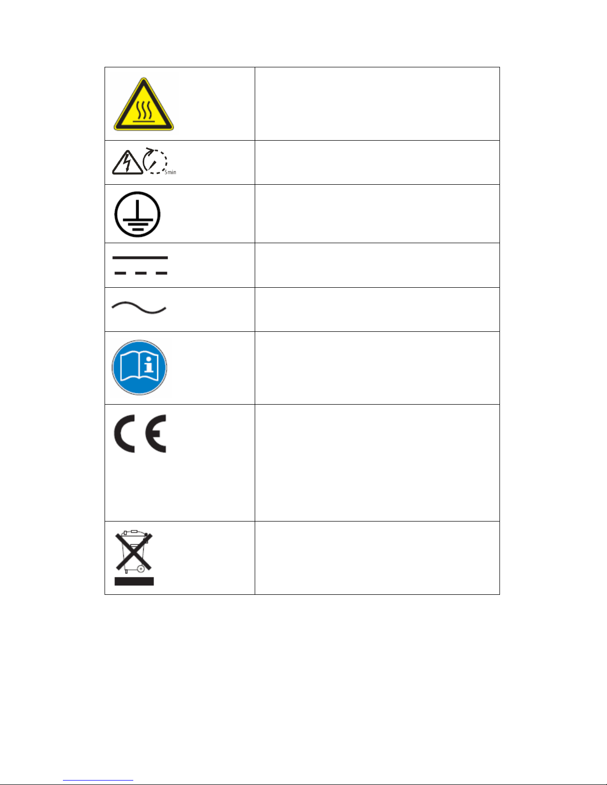
1.4.2 Markings on this product
Symbol
Explanation
Electrical voltage!
Risk of fire or explosion!
Page 7
7
Risk of burns
Operation after 5 minutes
Point of connection for grounding
protection
Direct Current (DC)
Alternating Current (AC)
Read the manual
CE mark.
The inverter complies with the
requirements of the applicable EC
guidelines.
The inverter must not be disposed of
with the household waste.
Page 8

8
1.5 Glossary
AC
Abbreviation for "Alternating Current"
DC
Abbreviation for "Direct Current"
Energy
Energy is measured in Wh (watt hours), kWh (kilowatt hours) or MWh (megawatt
hours). The energy is the power calculated over time. For example, your inverter
operates at a constant power of 4600 W for half an hour and then at a constant power
of 2300 W for another half an hour, it has fed 3450Wh of energy into the power
distribution grid within that hour.
Power
Power is measured in W (watts), kW (kilowatts) or MW (megawatts). Power is an
instantaneous value. It displays the power your inverter is currently feeding into the
power distribution grid.
Power rate
Power rate is the radio of current power feeding into the power distribution grid and
the maximum power of the inverter that can feed into the power distribution grid.
Power Factor
Power factor is the ratio of true power or watts to apparent power or volt amps. They
are identical only when current and voltage are in phase than the power factor is 1.0.
The power in an ac circuit is very seldom equal to the direct product of the volts and
amperes. In order to find the power of a single phase ac circuit the product of volts
and amperes must be multiplied by the power factor.
PV
Abbreviation for photovoltaic
wireless communication
The external wireless communication technology is a radio technology that allows the
inverter and other communication products to communicate with each other. The
external wireless communication does not require line of sight between the devices
and it is selective purchasing.
Page 9
9
2 Safety
2.1 Intended Use
The unit converts the DC current generated by the photovoltaic (PV) modules to grid-compliant
alternating current and performs single-phase feed-in into the electricity grid.MIN
2500TL-X,MIN 3000TL-X,MIN 3600TL-X,MIN 4200TL-X,MIN 4600TL-X,MIN 5000TL-X
inverters are built according to all required safety rules. Nevertheless, improper use may cause
lethal hazards for the operator or third parties, or may result in damage to the units and other
property.
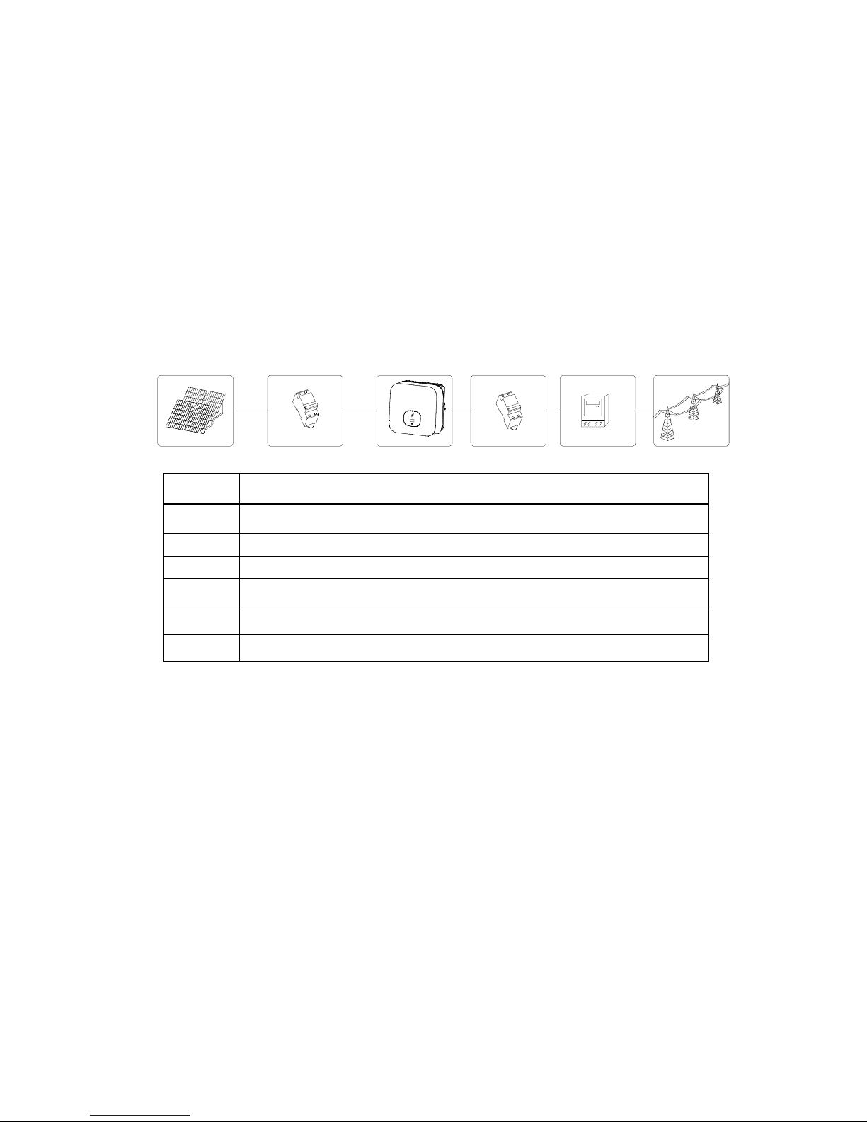
Principle of a PV plant with this MIN TL-X single-phase inverter
Position
Description
A
PV modules
B
DC load circuit breaker
C
Inverter
D
AC load circuit breaker
E
Energy meter
F
Utility grid
The inverter may only be operated with a permanent connection to the public power grid. The
inverter is not intended for mobile use. Any other or additional use is not considered the intended
use. The manufacturer/supplier is not liable for damage caused by such unintended use. Damage
caused by such unintended use is at the sole risk of the operator.
PV modules Capacitive Discharge Currents
PV modules with large capacities relative to earth, such as thin-film PV modules with cells on a
metallic substrate, may only be used if their coupling capacity does not exceed 1uF. During
feed-in operation, a leakage current flows from the cells to earth, the size of which depends on the
manner in which the PV modules are installed (e.g. foil on metal roof) and on the weather (rain,
snow). This "normal" leakage current may not exceed 50mA due to the fact that the inverter would
otherwise automatically disconnect from the electricity grid as a protective measure.
2.2 Qualification of skilled person
This grid-tied inverter system operates only when properly connected to the AC distribution
network. Before connecting the MIN TL-X to the power distribution grid, contact the local power
Page 10
10
distribution grid company. This connection must be made only by qualified technical personnel to
connect, and only after receiving appropriate approvals, as required by the local authority having
jurisdiction.
2.3 Safety instruction
The MIN TL-X Inverters is designed and tested according to international safety requirements
(IEC62109-1,CE,VDE0126-1-1, AS4777); however, certain safety precautions must be observed
when installing and operating this inverter. Read and follow all instructions, cautions and warnings
in this installation manual. If questions arise, please contact Growatt’s technical services at +86
(0)755 2747 1900.
2.4 Assembly Warnings
WARNING
Prior to installation, inspect the unit to ensure absence of any transport
or handling damage, which could affect insulation integrity or safety
clearances; failure to do so could result in safety hazards.
Assemble the inverter per the instructions in this manual. Use care
when choosing installation location and adhere to specified cooling
requirements.
Unauthorized removal of necessary protections, improper use,
incorrect installation and operation may lead to serious safety and
shock hazards and/or equipment damage.
In order to minimize the potential of a shock hazard due to hazardous
voltages, cover the entire solar array with dark material prior to
connecting the array to any equipment.
CAUTION
Grounding the PV modules:The MIN TL-X is a transformerless
inverter. That is why it has no galvanic separation. Do not ground the
DC circuits of the PV modules connected to the MIN TL-X. Only
ground the mounting frame of the PV modules.If you connect
grounded PV modules to the MIN TL-X, the error message "PV ISO
Low".
Comply with the local requirements for grounding the PV modules and
the PV generator. GROWATT recommends connecting the generator
frame and other electrically conductive surfaces in a manner which
ensures continuous conduction with ground in order to have optimal
protection of the system and personnel.
Page 11
11
2.5 Electrical Connection Warnings
2.6 Operation Warnings
DANGER
The components in the inverter are live. Touching live components can result
in serious injury or death.
Do not open the inverter except the wire box by qualified persons.
Electrical installation, repairs and conversions may only be carried out by
electrically qualified persons.
Do not touch damaged inverters.
Danger to life due to high voltages in the inverter
There is residual voltage in the inverter. The inverter takes 20 minutes to
discharge.
Persons with limited physical or mental abilities may only work with the
Growatt inverter following proper instruction and under constant supervision.
Children are forbidden to play with the Growatt inverter. Must keep the
Growatt inverter away from children.
WARNING
Make all electrical connections (e.g. conductor termination, fuses, PE
connection, etc.) in accordance with prevailing regulations. When working
with the inverter powered on, adhere to all prevailing safety regulations to
minimize risk of accidents.
Systems with inverters typically require additional control (e.g., switches,
disconnects) or protective devices (e.g., fusing circuit breakers) depending
upon the prevailing safety rules.
WARNING
Ensure all connectors are sealed and secure during operation.
Although designed to meet all safety requirements, some parts and
surfaces of Inverter are still hot during operation. To reduce the risk of
injury, do not touch the heat sink at the back of the PV-Inverter or nearby
surfaces while Inverter is operating.
Incorrect sizing of the PV plant may result in voltages being present
which could destroy the inverter. The inverter display will read the error
message “PV voltage High!”
Turn the rotary switch of the DC Disconnect to the Off position
immediately.
Contact installer.
CAUTION
All operations regarding transport, installation and start-up, including
maintenance must be operated by qualified, trained personnel and in
compliance with all prevailing codes and regulations.
Anytime the inverter has been disconnected from the power network, use
extreme caution as some components can retain charge sufficient to
Page 12
12
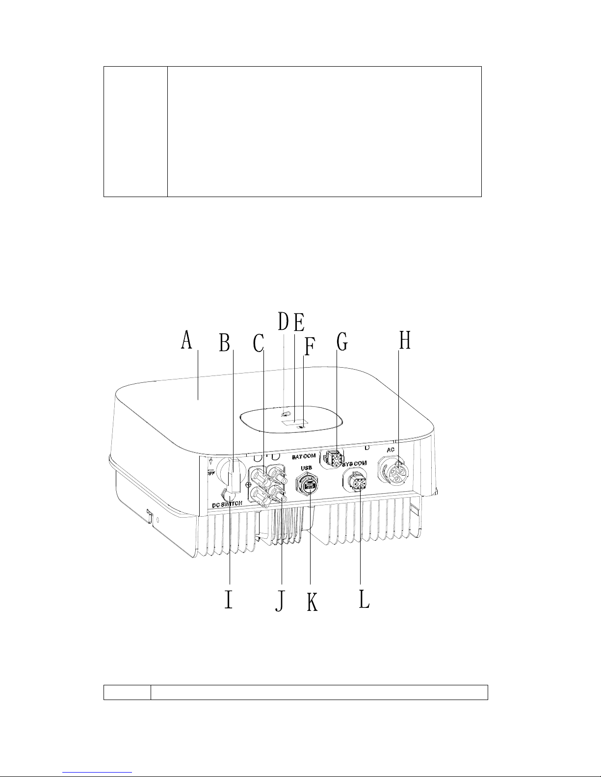
3 Product description
3.1 TL-X Overview
Position
Description
create a shock hazard; to minimize occurrence of such conditions,
comply with all corresponding safety symbols and markings present on
the unit and in this manual.
In special cases, there may still be interference for the specified
application area despite maintaining standardized emission limit values
(e.g. when sensitive equipment is located at the setup location or when
the setup location is near radio or television receivers).In this case, the
operator is obliged to take proper action to rectify the situation.
Do not stay closer than 20 cm to the inverter for any length of time.
Page 13
13
A
Cover
B
DC SWITCH
C
PV INPUT +
D
LED
E
OLED
F
TOUCH BUTTON
G
DRM PORT
H
AC OUTPUT
I
VENTILATION VALVE
J
PV INPUT-
K
USB PORT
L
COM PORT
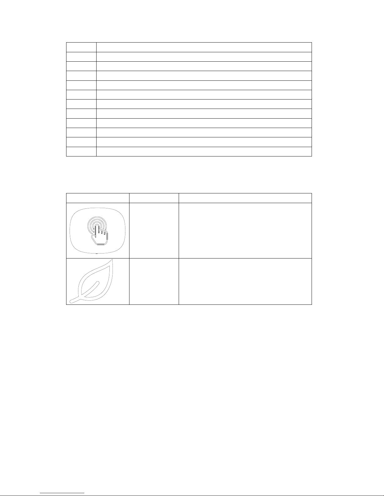
Symbol on the inverter
Symbol
Description
Explanation
Touch symbol
Touch button.We can switch the OLED display
and set parameter by touching.
Inverter status
symbol
Indicates inverter operation status:
Red:Fault.
Green:Nomal.
Red leaf flash:Warning or DSP Programming.
Green leaf flash:M3 Programming.
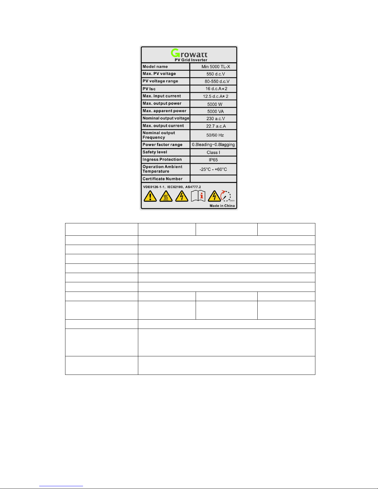
3.2 Type label
The type labels provide a unique identification of the inverter (The type of product,
Device-specific characteristics, Certificates and approvals). The type labels are on the
left-hand side of the enclosure.
Page 14
14
More detail about the type label as the chart below:
Model Name
MIN 2500 TL-X
MIN 3000 TL-X
MIN 3600 TL-X
Max input DC voltage
500V
Max input DC current
12.5A/12.5A
Start voltage
100V
MPP voltage range
80V~500V
AC nominal voltage
230V
AC grid frequency
50/60 Hz
Max. apparent power
2500VA
3000VA
3600VA
AC normal output
current
10.8A
13A
15.6A
Power factor
0.8leading…0.8lagging
Environmental
Protection
Rating
IP65
Operation Ambient
temperature
-25...+60℃ (-13...+ 140°F)
with derating above 45°C(113°F)
Page 15
15
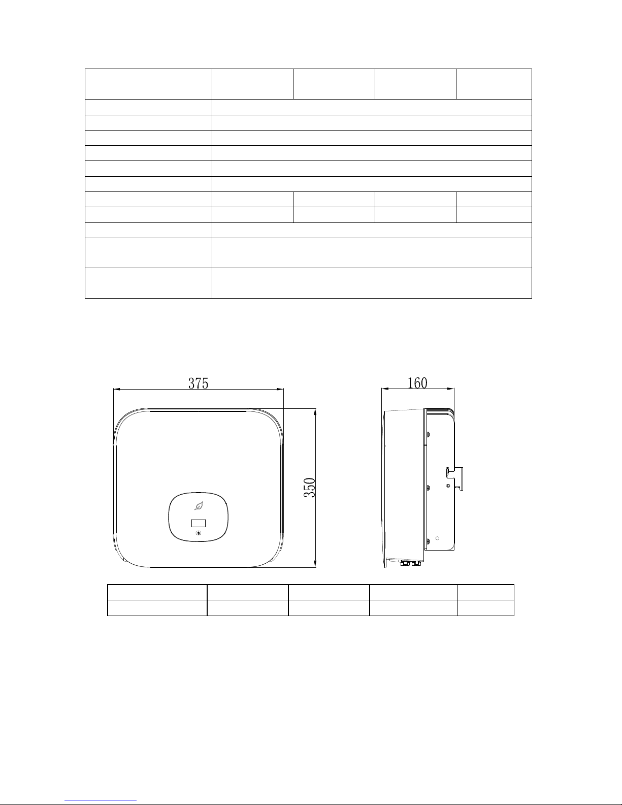
3.3 Size and weight
Dimensions and weight
Model
Height (H)
Width (W)
Depth (D)
Weight
MIN 2500-6000 TL-X
350mm 13.8inch
375mm 14.8inch
160mm 6.3inch
10.8kg
3.4 Storage of Inverter
If you want to storage the inverter in your warehouse, you should choose an
appropriate location to store the inverter.
The unit must be stored in original package and desiccant must be left in the
Model Name
MIN 4200 TL-X
MIN 4600 TL-X
MIN 5000 TL-X
MIN 6000
TL-X
Max input DC voltage
550V
Max input DC current
12.5A/12.5A
Start voltage
100V
MPP voltage range
80V~550V
AC nominal voltage
230V
AC grid frequency
50/60 Hz
Max. apparent power
4200VA
4600VA
5000VA
6000 VA
AC normal output current
18.2A
20A
21.7A
26A
Power factor
0.8leading…0.8lagging
Environmental Protection
Rating
IP65
Operation Ambient
temperature
-25...+60℃ (-13...+ 140°F)
with derating above 45°C(113°F)
Page 16

16
package.
The storage temperature should be always between -25℃and +60℃. And the
storage relative humidity can achieve to 100%.
If there are a batch of inverters need to be stored, the maximum layers for original
carton is four.
After long term storage, local installer or service department of GROWATT
should perform a comprehensive test before installation.
3.5 The advantage of the unit
Maximum efficiency of 98.4%
Wide input voltage range from 80--550Vdc
Reactive power regulate
Integrated DC switch
Multi MPP controller
DSP controller
Touch control
Multi active power control mode
Easy installation
4 Unpacking and inspection
The inverter is thoroughly tested and inspected strictly before delivery. Our inverters
leave our factory in proper electrical and mechanical condition. Special packaging
ensures safe and careful transportation. However, transport damage may still occur.
The shipping company is responsible in such cases. Thoroughly inspect the inverter
upon delivery. Immediately notify the responsible shipping company if you discover
any damage to the packaging which indicates that the inverter may have been
damaged or if you discover any visible damage to the inverter. We will be glad to
assist you, if required. When transporting the inverter, the original or equivalent
packaging should be used, and the maximum layers for original carton is four, as this
ensures safe transport.
After opening the package, please check the contents of the box. It should contain the
following, Please check all of the accessories carefully in the carton. If anything
missing, contact your dealer at once.
Page 17

17
Object
Description
Quantity
A
Inverter 1 B
Mounting bracket
1
C
Quick Guide
1
D
Monitor(Optional)
1
E
Signal connector
1
DRED connector (only for Australia)
1
F
Self-tapping screws
3
G
Plastic expansion pipe
3
H
PV+/PV- terminal
2/2
I
PV+/PV- metal terminal
2/2
J
AC connector
1
K
Uninstall PV tool
1
L
Uninstall signal or AC connector tool
1
Page 18

18
5 Installation
5.1 Safety instructions
Danger to life due to fire or explosion
Despite careful construction, electrical devices can cause fires.
Do not install the inverter on easily flammable materials and
where flammable materials are stored.
Risk of burns due to hot enclosure parts
Mount the inverter in such a way that it cannot be touched
inadvertently.
Possible damage to health as a result of the effects of radiation!
In special cases, there may still be interference for the specified
application area despite maintaining standardized emission limit
values (e.g. when sensitive equipment is located at the setup
location or when the setup location is near radio or television
receivers).In this case, the operator is obliged to take proper
action to rectify the situation.
Never install the inverter near the sensitive equipment(e.g.
Radios, telephone, television, etc)
Do not stay closer than 20 cm to the inverter for any length of
time unless it is absolutely necessary.
Growatt assumes no responsibility for compliance to EMC
regulations for the complete system
All electrical installations shall be done in accordance with the local and national
electrical codes. Do not remove the casing. Inverter contains no user serviceable
parts. Refer servicing to qualified service personnel. all wiring and electrical
installation should be conducted by a qualified service personnel .
Carefully remove the unit from its packaging and inspect for external damage. If
you find any imperfections, please contact your local dealer.
Be sure that the inverters connect to the ground in order to protect property and
personal safety.
The inverter must only be operated with PV generator. Do not connect any other
source of energy to it.
Both AC and DC voltage sources are terminated inside the PV Inverter. Please
disconnect these circuits before servicing.
This unit is designed to feed power to the public power grid (utility) only. Do not
connect this unit to an AC source or generator. Connecting Inverter to external
devices could result in serious damage to your equipment.
Page 19

19
When a photovoltaic panel is exposed to light, it generates a DC voltage. When
connected to this equipment, a photovoltaic panel will charge the DC link
capacitors.
Energy stored in this equipment’s DC link capacitors presents a risk of electric
shock. Even after the unit is disconnected from the grid and photovoltaic panels,
high voltages may still exist inside the PV-Inverter. Do not remove the casing
until at least 5 minutes after disconnecting all power sources.
Although designed to meet all safety requirements, some parts and surfaces of
Inverter are still hot during operation. To reduce the risk of injury, do not touch
the heat sink at the back of the PV-Inverter or nearby surfaces while Inverter is
operating.
5.2 Selecting the installation location
This is guidance for installer to choose a suitable installation location, to
avoid potential damages to device and operators.
The installation location must be suitable for the inverter's weight and
dimensions for a long period time.
Select the installation location so that the status display can be easily viewed.
Do not install the inverter on structures constructed of flammable or
thermolabile materials.
Never install the inverter in environment of little or no air flow, nor dust
environment. That may derate the efficiency of the cooling fan of the
inverter.
The Ingress Protection rate is IP65 which means the inverter can be installed
outdoors and indoors.
The humidity of the installation location should be 0~100% without
condensation.
The installation location must be freely and safely to get at all times.
Vertically installation and make sure the connection of inverter must be
downwards. Never install horizontal and avoids forward and sideways tilt.
Page 20

20
Be sure that the inverter is out of the children’s reach.
Don’t put any things on the inverter. Do not cover the inverter.
Do not install the inverter near television antenna or any other antennas and
antenna cables.
Inverter requires adequate cooling space. Providing better ventilation for the
inverter to ensure the heat escape adequately. The ambient temperature
should be below 40°C to ensure optimum operation.
Do not expose the inverter to direct sunlight, as this can cause excessive
heating and thus power reduction.
Observe the Min. clearances to walls, other inverters, or objects as shown
below:
Ambient dimensions of one inverter
Page 21

21
Ambient dimensions of series inverters
There must be sufficient clearance between the individual inverters to
ensure that the cooling air of the adjacent inverter is not taken in.
If necessary, increase the clearance spaces and make sure there is enough
fresh air supply to ensure sufficient cooling of the inverters.
The inverter can’t install to solarization,drench,firn location. We suggest that the inverters should
be installed at the location with some cover or protection。
Please make sure the inverter is installed at the right place.The inverter
can’t install close to trunk。
Page 22

22
5.3 Mounting the Inverter
5.3.1 Mounting the Inverter with bracket
DANGER
In order to avoid electrical shock or other injury, inspect existing
electronic or plumbing installations before drilling holes.
Fix the mounting bracket as the figure shows. Do not make the screws to be
flush to the wall. Instead, leave 2 to 4mm exposed.
Page 23

23
5.3.2 Fixed the inverter on the wall
WARNING
Falling equipment can cause serious or even fatal injury, never
mount the inverter on the bracket unless you are sure that the
mounting frame is really firmly mounted on the wall after
carefully checking.
Type1:
Rise up the inverter a little higher than the bracket. Considered the weight
of them.During the process please maintain the balance of the inverter.
Hang the inverter on the bracket through the match hooks on bracket.
After confirming the inverter is fixed reliably, fasten one M6 safety-lock sockets
head cap screws on the right or left side firmly to prevent the inverter from being
lifted off the bracket.
Page 24

24
6 Electrical connection
Decisive Voltage Class (DVC) indicated for ports
Port Name
Class
AC C DC C DRMS
A
RS485&RS232
A
.
6.1 Safety
Danger to life due to lethal voltages!
High voltages which may cause electric shocks are present in the
conductive parts of the inverter. Prior to performing any work on the
inverter, disconnect the inverter on the AC and DC sides
WARNING
Danger of damage to electronic components due to electrostatic discharge.
Take appropriate ESD precautions when replacing and installing the
inverter.
6.2 Wiring AC Output
WARNING
You must install a separate single-phase circuit-breaker or other load
disconnection unit for each inverter in order to ensure that the inverter
can be safely disconnected under load.
NOTE :The inverter has the function of detecting residual current and
protecting the inverter against residual current. If your inverter has to equip
a AC breaker which has the function of detecting residual current ,you must
choose a AC breaker with the rating residual current more than 300mA.
You must install a separate single-phase circuit-breaker or other load disconnection
Page 25

25
unit for each inverter in order to ensure that the inverter can be safely disconnected
under load.
We suggest you choice the AC breaker rating current in this table:
MIN 2500 TL-X
16A/230V
MIN 3000 TL-X
16A/230V
MIN 3600 TL-X
20A/230V
MIN 4200 TL-X
25A/230V
MIN 4600 TL-X
25A/230V
MIN 5000 TL-X
32A/230V
MIN 6000 TL-X
32A/230V
The AC wiring step:
1. Uninstall the parts of the AC connection plug from the accessory bag.
2. Insert the stripped and bared cable through pressure screw, seal ring, threaded sleeve in
sequence, insert cables into connection terminal according to polarities indicates on it and
tighten the screws firmly. Please try to pull out the wire to make sure the it’s well connected.
Page 26

26
3. Push the threaded sleeve into the socket, Tighten up the cap on the terminal.
4. Finally, Push or screw the threaded sleeve to connection terminal until both are locked tightly
on the inverter.
Page 27

27
5:To remove the AC output terminal, press the bayonet out of the slot with a small screwdriver and
pull it out,or unscrew the threaded sleeve,then pull it out.
Wire suggestion length:
Conductor cross
section
Max. cable length
MIN 2500 TL-X
MIN 3000 TL-X
MIN 3600 TL-X
4 mm² 12AWG
48m
40m
33m
Page 28

28
5.2 mm² 10AWG
60m
50m
42m
Conductor cross
section
Max. cable length
MIN 4200 TL-X
MIN 4600 TL-X
MIN 5000 TL-X
MIN 6000 TL-X
5.2 mm² 10AWG
28m
26m
24m
6.6 mm² 9AWG
36m
33m
30m
6.3 Connecting the second protective conductor
In some installation countries, a second protective conductor is required to prevent a touch current
in the event of a malfunction in the original protective conductor.For installation countries falling
within the scope of validity of the IEC standard 62109, you must install the protective conductor
on the AC terminal with a conductor cross-section of at least 10 mm²Cu.Or Install a second
protective conductor on the earth terminal with the same cross-section as the original
protective conductor on the AC terminal. This prevents touch current if the original protective
conductor fails.
6.4 Connecting the PV Array (DC input)
6.4.1 Conditions for DC Connection
The inverter shall be used with IEC 61730 Class A rating PV module.
Please use the same brand male and female PV connectors.
Page 29

29
WARNING
The MIN TL-X single-phase inverter has 2 independent input : PV1 & PV2
Notice that the connectors are in paired (male and female connectors). The connectors
for PV arrays and inverters are VP-D4 connectors;
CAUTION
If the inverter is not equipped with a DC switch but this is mandatory in the
country of installation, install an external DC switch.
The following limit values at the DC input of the inverter must not be exceeded:
Types
Max current PV1
Max current input B
Max voltage
2500-3600 TL-X
12.5A
12.5A
500V
4200-6000 TL-X
12.5A
12.5A
550V
6.4.2 Connecting the PV Array (DC input)
DANGER
Danger to life due to lethal voltages!
PV array supplies d.c voltage to inverter when exposed to light,before connecting
the PV array, conver some light screens above PV arrays,ensure that the DC
switch and AC breaker are disconnect from the inverter. NEVER connect or
disconnect the DC connectors under load.
Make sure the maximum open circuit voltage(Voc) of each PV string is
less than the maximum input voltage of the inverter.
Check the design of the PV plant. The Max. open circuit voltage, which can
occur at solar panels temperature of -10℃, must not exceed the Max. input
Page 30

30
voltage of the inverter.
WARNING
Improper operation during the wiring process can cause fatal injury to operator or
unrecoverable damage to the inverter. Only qualified personnel can perform the
wiring work.
Please don’t connect PV array positive or negative pole to the ground, it could
cause serious damages to the inverter
Check the connection cables of the PV modules for correct polarity and make
sure that the maximum input voltage of the inverter is not exceeded.
Connection of PV terminal
6.5 Connecting signal cable
This series inverter has one 8 Pin signal connector(There are two connectors for
AS/NZS4777 model ) . Signal Cable Ports:
Page 31

31
Procedure
Step 1 Insert the stripped and bared cable through pressure screw, seal ring, threaded sleeve in
sequence, insert cables into connection terminal according to number indicates on it and tighten
the screws firmly. Please try to pull out the wire to make sure the it’s well connected.
Step 2 Push the threaded sleeve into the socket, Tighten up the cap on the terminal.
Step 3 Push the threaded sleeve to connection terminal until both are locked tightly on the
inverter.
Uninstall signal connector
Step 1 Press the fasteners and pull it out from the inverter.
Step 2 Insert the H type tool and pull it out from the socket.
Page 32

32
6.6 Grounding the inverter
The inverter must be connected to the AC grounding conductor of the power
distribution grid via the ground terminal (PE) .
WARNING
Because of the transformerless design, the DC positive pole and DC negative
pole of PV arrays are not permitted to be grounded.
6.7 Active power control with smart meter , CT or ripple
control signal receiver
Information
The position of export limitation CT or Meter must between the
Inverter & Load and gird.
This series inverter has integrated export limitation functionality. To use this function,
you can connect smart meter or CT. The smart meter model is Eastron
SDM230-Modbus. The CT Model is TOP 90-S10/SP4(LEM).The primary aperture is
10mm,output cable length is 5m . The arrow on the CT must pointing towards the
inverter.
Active power control with a ripple control signal receiver.
Page 33

33
6.8 Inverter demand response modes (DRMS)
This series inverter has the function of demand response modes, We use 8Pin socket
as inverter DRMS connection.
Information
DRMS application description
Only applicable to AS/NZS4777.2:2015.
DRM0, DRM5, DRM6, DRM7, DRM8 are available.
CAUTION
Damage to the inverter due to moisture and dust penetration
Make sure the cable gland has been tightened firmly.
If the cable gland are not mounted properly, the inverter can
be destroyed due to moisture and dust penetration. All the
warranty claim will be invalid.
6.8.1 8Pin socket pin assignment
Pin
Assignment for inverters capable
of both charging and discharging
1
DRM 5
2
DRM 6
3
DRM 7
4
DRM 8
5
RefGen
6
Com/DRM0
7
NC 8 NC
6.8.2 Method of asserting demand response modes
Mode
Socket Asserted
by shorting pins
Requirement
DRM 0
5
6
Operate the disconnection device
DRM 5
1
5
Do not generate power
DRM 6
2
5
Do not generate at more than 50% of rated power
DRM 7
3
5
Do not generate at more than 75% of rated power
AND Sink reactive power if capabie
DRM 8
4
5
Increase power generation (subject to constraints from
other active DRMs)
7 Commissioning
Page 34

34
DANGER
Do not disconnect the DC connectors under load.
WARNING
Improper operation during the wiring process can cause fatal injury to operator
or unrecoverable damage to the inverter. Only qualified personnel can perform
the wiring work.
CAUTION
Damage to the inverter due to moisture and dust penetration
Make sure the cable gland has been tightened firmly.
If the cable gland are not mounted properly, the inverter can be
destroyed due to moisture and dust penetration. All the warranty
claim will be invalid.
Requirements:
The AC cable is correctly connected.
The DC cable is correctly connected.
The country is set incorrectly.
7.1 Start the inverter
7.1.1 Touch control
Touch
Description
Single touch
Switch display or Number +1
Double touch
Enter or confirmation
Three touch
Previous menu
Hold 5s
Confirm country or recover
defaut value
7.1.2 Country setting
Information
Country setting
When the inverter start up,we need to select the right country,if
we don’t select any country, the inverter will run under
AS/NZS4777.2 as default for Australia,or run under
VDE0126-1-1 for other region after 30s.
When inverter powered on, OLED will light automatically. Once the PV power is
sufficient, OLED displays the following:
Growatt
PV inverter
Set Country
XXXX
Page 35

35
Press the touch key once a second to scroll through the different Country, showing on
the screen will constantly change.For example, if you want to choose Newzealand,
press the control key until the OLED display shows “Newzealand” as below:
Set Country
Newzealand
Press the touch key 5S, the OLED shows Country setting is complete.
Set OK
7.2 General setting
7.2.1 Set inverter display language
This series inverter provides multi languages.
Single touch to switch different language.
Double touch to confirm you setting.
Set the language as described below:
Set Language
English
General
Advanced
Set parameter
7.2.2 Set inverter COM address
The default COM address is 1.We can change COM address as described below:
Single touch to switch display or make the number +1.
Hold 5s ,the COM address become 001.
Double touch to confirm you setting.
Page 36

36
Set Comaddr
001
Set Language
English
General
Advanced
Set parameter
7.2.3 Set inverter date & time
Single touch make the number +1.
Double touch to confirm you setting.
Hold 5s recover defaut value.
Set Date
2018-12-14
Set Time
12:30:30
Set Date
2018-12-14
Set Date
2018-12-14
Set Time
12:30:30
Set Time
12:30:30
Set OK Set OK
Set Comaddr
001
Set Language
English
General
Advanced
Set parameter
Page 37

37
7.3 Advanced setting
7.3.1 Reset Country
Single touch to switch display or make the number +1.
Double touch to confirm you setting.
The password of advanced setting is 123.
Set Country
VDE0126
Set Country
xxxxxxx
Set OK
Set parameter
General
Advanced
Password
123
7.3.2 Export limitation setting
Single touch to switch display or make the number +1.
Double touch to confirm you setting.
Exporlimit
OFF ON
Meter
CT
Set OK
Set parameter
General
Advanced
Password
123
7.3.3 Reset factory
Information
Perform this operation with caution because all configured parameters
except the current date,time, and model parameters will be restored to
their factory defaults.
Page 38

38
Single touch to switch display or make the number +1.
Double touch to confirm you setting.
Reset factory
NO
YES
Set OK
Set parameter
General
Advanced
Password
123
7.3 Communications
7.4 RS485
This series inverter provides two RS485 ports. You can monitor one or more inverters
by RS485.Another RS485 port is for smart meter(Export limitation functionality.).
7.5 USB-A
USB-A port is mainly for connecting monitor or firmware updage:
Through USB connection,we can connect external optional monitor ,for
example :Shine WIFI-X,Shine 4G-X, Shine LAN-X,ect.
And also you can quickly update the software by U disk.
We can monitor as below:
Make sure the △ on the front side, then insert the monitor,
fasten the screw.
NO.
Definition
NO.
Definition
1
+12V Power Supply(<1W)
2
COM
3
RS485A1 signal for
communication
4
RS485B1 signal for
communication
5
CT-P 6 CT- N
7
RS485A2 signal for
Smart Meter
8
RS485B2 signal for Smart
Meter
Page 39

39
8 Start-Up and shut down the inverter
8.1 Start-Up the inverter
1. Connect the AC breaker of the inverter.
2. Turn on the dc switch, and the inverter will start automatically when the input
voltage is higher than 70 V.
8.2 Turn-off the Inverter
DANGER
Do not disconnect the DC connectors under load.
Turn-off the inverter step:
1. Disconect the line circuit breaker from single-phases grid and prevent it from
being reactivated.
2. Turn off the dc switch.
3. Check the inverter operating status.
4. Waiting until LED, OLED have go out, the inverter is shut down.
9 Maintenance and Cleaning
9.1 Checking Heat Dissipation
If the inverter regularly reduces its output power due to high temperature,
please improve the heat dissipation condition. Maybe you need to clean the
heat sink.
Page 40

40
9.2 Cleaning the Inverter
If the inverter is dirty, turn-off the AC breaker and DC switch ,waiting the
inverter shut down ,then clean the enclosure lid, the display, and the LEDs
using only a wet cloth. Do not use any cleaning agents (e.g. solvents or
abrasives).
9.3 Checking the DC Disconnect
Check for externally visible damage and discoloration of the DC Disconnect
and the cables at regular intervals.If there is any visible damage to the DC
Disconnect, or visible discoloration or damage to the cables, contact the
installer.
Once a year, turn the rotary switch of the DC Disconnect from the On
position to the Off position 5 times in succession. This cleans the contacts
of the rotary switch and prolongs the electrical endurance of the DC
Disconnect.
10 Trouble shooting
Our quality control program assures that every inverter is manufactured to accurate specifications
and is thoroughly tested before leaving our factory. If you have difficulty in the operation of your
inverter, please read through the following information to correct the problem.
10.1 Error Messages displayed on OLED
An error message will be displayed on the OLED screen when a fault occurs. The faults consist of
system fault and inverter fault.
You may be advised to contact Growatt in some situation, please provide the following
information.
Information concerning the inverter:
Serial number
Model number
Error message on OLED
Short description of the problem
Grid voltage
DC input voltage
Can you reproduce the failure? If yes, how?
Page 41

41
Has this problem occurred in the past?
What was the ambient condition when the problem occurred?
Information concerning the PV panels:
Manufacturer name and model number of the PV panel
Output power of the panel
Voc of the panel
Vmp of the panel
Imp of the panel
Number of panels in each string
If it is necessary to replace the unit, please ship it in the original box.
10.2 System fault
System fault (system faults are mainly caused by system instead of inverter, please check the
items as instructed below before replacing inverter).
Error message
Description
Suggestion
Residual I High
Error: 201
Leakage current too high
1.Restart the invert.
2. If error message still exists, contact
Growatt.
PV Voltage High
Error: 202
The DC input voltage is exceeding
the maximum tolerable value.
1. Disconnect the DC switch immediately.
2. Check the voltage of each PV string
with multimerter.
3. If the voltage of PV string is lower than
550V, contact Growatt.
PV Isolation Low
Error: 203
Insulation problem
1. Check if panel enclosure ground
properly.
2. Check if inverter ground properly.
3. Check if the DC breaker gets wet.
4. Check the impedance of PV (+) & PV (-)
between ground (must be more than 25 KΩ
or 550 KΩ(VDE 0126)). If the error message
is displayed despite the above checking
passed, contact Growatt.
AC V Outrange
Error: 300
Utility grid voltage is out of
permissible range.
Please switch off DC switch.
Check AC wiring, especially neutral and
ground wire.
Check grid voltage is complied with local
grid standard. Restart inverter, if problem
still exist, Contact Growatt.
Page 42

42
No AC connection
Error: 302
No AC connection
Check AC wiring.
Check the status of AC breaker
AC F Outrange
Error: 303
Utility grid frequency out of
permissible range.
Please switch off DC switch.
Check AC wiring, especially neutral and
ground wire.
Check grid frequency is complied with local
grid standard. Restart inverter, if problem
still exist, Contact Growatt.
PE abnormal
Error: 304
Voltage of Neutral and PE above
30V.
1. Check the voltage of Neutral and PE.
2. Check AC wiring.
3. Restart inverter, if error message still
exisits,contact Manufacturer
Auto Test Failed
Error: 407
Auto test didn’t pass.
Restart inverter, repeat Auto Test, if
problem still exist, contact Growatt.
Page 43

43
10.3 Inverter warning
Warning code
Meanings
Suggestion
Warning202
DC SPD function abnormal
1.After shutdown,Check the DC SPD.
2.If error message still exists,contact
manufacturer.
Warning 203
PV1 or PV2 Circuit short
Check the PV panel polarity.
Restart the inverter. If the warning still
exist, please contact Growatt customer
service to replace the POWER board.
Warning204
Dryconnect function abnormal
1.After shutdown,Check the dry
Dryconnect wiring.
2.If the error message still exists, contact
manufacturer.
Warning 205
PV1 or PV2 boost broken
Restart the inverter. If the warning still
exist, please contact Growatt customer
service to replace the power board.
Warning207
USB over-current
1: Unplug the U disk or monitor.
2: Re-access U disk or monitor after
shutdown.
3.If the error message still exists, contact
manufacturer.
Warning 401
Inverter communicates with
Meter abnormal
1: Check if the meter is on
2: Check the inverter and the meter
connection is normal
Warning404
EEPROM abnormal
Restart the inverter. If the warning still
exist, please contact Growatt customer
service to replace the M3 board.
Warning405
Firmware version is not
consistent
Uptate the right version firmware
10.4 Inverter fault
Error code
Meanings
Suggestion
Error: 402
Output High DCI
Restart inverter, if problem still exist,
Contact Growatt.
Error: 404
Bus sample fault
Restart inverter, if problem still exist,
Contact Growatt.
Error: 405
Relay fault
Restart inverter, if problem still exist,
Contact Growatt.
Error: 408
Over Temperature
If the ambient temperature of inverter is
Page 44

44
lower than 60°C , restart inverter, if error
message still exists, contact Growatt.
Error: 409
Bus over voltage
Restart inverter, if problem still exist,
Contact Growatt.
Error: 411
DSP communicates with M3
abnormal
Restart inverter, if problem still exist,
update the DSP&M3 firmware;
Change DSP board or M3 board, if problem
still exist, contact Growatt.
Error: 414
EEPROM fault.
Restart inverter, if problem still exist,
Contact Growatt.
Error: 417
The data sampled by the DSP and
redundant M3 is not the same.
Restart inverter, if problem still exist,
Contact Growatt.
Error: 420
GFCI fault.
Restart inverter, if problem still exist,
change power board, or contact Growatt.
Page 45

45
11 Manufacturer Warranty
Please refer to the warranty card.
12 Decommissioning
12.1 Dismantling the Inverter
1 Disconnect the inverter as described in section 8 .
2 Remove all connection cables from the inverter.
CAUTION
Danger of burn injuries due to hot enclosure parts!
Wait 20 minutes before disassembling until the housing has cooled down.
3 Screw off all projecting cable glands.
4 Lift the inverter off the bracket and unscrew the bracket screws.
12.2 Packing the Inverter
If possible, always pack the inverter in its original carton and secure it with tension
belts. If it is no longer available, you can also use an equivalent carton. The box must
be capable of being closed completely and made to support both the weight and the
size of the inverter.
12.3 Storing the Inverter
Store the inverter in a dry place where ambient temperatures are always between
-25°C and +60°C.
12.4 Disposing of the Inverter
Do not dispose of faulty inverters or accessories together with household
waste. Please accordance with the disposal regulations for electronic waste
which apply at the installation site at that time. Ensure that the old unit and,
where applicable, any accessories are disposed of in a proper manner
Page 46

46
13 Technical Data
13.1 Specification
Model
Specifications
2500TL-X
3000TL-X
3600TL-X
4200TL-X
Input data(DC)
Max. recommended PV
power(for module STC)
3500W
4200W
5040W
5880W
Max. DC voltage
500V
Start voltage
100V
Nominal voltage
360V
MPP voltage range
80-500
80-500
80-550
80-550
MPP voltage range at Full
Power
100V-450V
120V-450V
150V-500V
170V-500V
No. of MPP trackers
2
No. of PV strings per MPP
trackers
1
Max. input current per MPP
trackers
12.5A
Max. short-circuit current per
MPP trackers
16A
DC overvoltage category
Category II
Output data(AC)
AC nominal power
2.5kW
3kW
3.6kW
4.2kW
Max. AC apparent power
2.5kVA
3kVA
3.6kVA
4.2kVA
Nominal AC voltage/range*
230/
160~300V
230/
160~300V
230/
160~300V
230/
160~300V
AC grid frequency/range
50-60Hz/44-55Hz;54-65Hz
Max. output current
11.3A
13.6A
16A
19A
Inrush current
<10A
Max output fault current
53A
Max output overload protection
16A
16A
20A
25A
Backfeed current
0A
Power factor(@nominal power)
>0.99
Adjustable power factor
0.8leading… 0.8lagging
THDi
<3%
AC grid connection type
Single phase
AC overvoltage category
Category III
Efficiency
Page 47

47
Max. efficiency
98.2%
98.2%
98.2%
98.4%
Euro-eta
97.1%
97.1%
97.2%
97.2%
Protection devices
DC reverse-polarity protection
Integrated
DC switch
Integrated
DC Surge protection
Type II
Insulation resistance
monitoring
Integrated
AC surge protection
Type III
AC short-circuit protection
Integrated
Ground fault monitoring
Integrated
Grid monitoring
Integrated
Anti-islanding protection
Integrated
Residual-current monitoring
unit
Integrated
General data
Dimensions (W / H / D) in mm
375*350*160
Weight
10.8 kg
Operating temperature range
–25 °C ... +60 °C
Noise emission (typical)
≤ 25 dB(A)
Altitude
4000m
Internal consumption at night
<1W
Topology
transformerless
Cooling
Natural convection
Protection degree
IP65
Relative humidity
0~100%
DC connection
VP-D4/MC4(Optional)
AC connection
AC connector
Interfaces
Display
OLED+LED
RS485/USB
Integrated
WIFI/GPRS/4G/LAN/ RF
Optional
Warranty:5/10 years
Yes/ Optional
Model
Specifications
4600TL-X
5000TL-X
6000TL-X
Input data(DC)
Max. recommended PV
power(for module STC)
6440W
7000W
8100W
Max. DC voltage
550V
Start voltage
100V
Nominal voltage
360V
Page 48

48
MPP voltage range
80-550
80-550
80-550
MPP voltage range at Full
Power
185V-500V
200V-500V
235V-500V
No. of MPP trackers
2
No. of PV strings per MPP
trackers
1
Max. input current per MPP
trackers
12.5A
Max. short-circuit current per
MPP trackers
16A
DC overvoltage category
Category II
Output data(AC)
AC nominal power
4.6kW
5kW
6kW
Max. AC apparent power
4.6kVA
5kVA
6kVA
Nominal AC voltage/range*
230/
160~300V
230/
160~300V
230/
160~300V
AC grid frequency/range
50-60Hz/44-55Hz;54-65Hz
Max. output current
20.9
22.7A
27.2A
Inrush current
<10A
Max output fault current
53A
Max output overload protection
25A
32A
32A
Backfeed current
0A
Power factor(@nominal
power)
>0.99
Adjustable power factor
0.8leading… 0.8lagging
THDi
<3%
AC grid connection type
Single phase
AC overvoltage category
Category III
Efficiency
Max. efficiency
98.4%
98.4%
98.4%
Euro-eta
97.5%
97.5%
97.5%
Protection devices
DC reverse-polarity protection
Integrated
DC switch
Integrated
DC Surge protection
Type II
Insulation resistance
monitoring
Integrated
AC surge protection
Type III
AC short-circuit protection
Integrated
Ground fault monitoring
Integrated
Grid monitoring
Integrated
Anti-islanding protection
Integrated
Residual-current monitoring
Integrated
Page 49

49
unit
General data
Dimensions (W / H / D) in mm
375*350*160
Weight
10.8 kg
Operating temperature range
–25 °C ... +60 °C
Noise emission (typical)
≤ 25 dB(A)
Altitude
4000m
Internal consumption at night
<1W
Topology
transformerless
Cooling
Natural convection
Protection degree
IP65
Relative humidity
0~100%
DC connection
VP-D4/MC4(Optional)
AC connection
AC connector
Interfaces
Display
OLED+LED
RS485/USB
Integrated
WIFI/GPRS/4G/LAN/ RF
Optional
Warranty:5/10 years
Yes/ Optional
13.2 DC &AC connector info
DC connector
VP-D4/ MC4(opt)
AC connector
M-S30_SD03_S10 001U-A
VPAC06EP-3S(SC)5
VPAC06EW-3P(SC)
13.3 Torque
Enclosure lid screws
12kg.cm
AC terminal
6kg.cm
Signal terminal
4kg.cm
Safety screw
12kg.cm
Additional ground screws
12kg.cm
13.4 Accessories
In the following table you will find the optional accessories for your product. If
required, you can order these from GROWATT NEW ENERGY TECHNOLOGY
Page 50

50
CO.,LTD or your dealer.
Name
Brief description
Shine WIFI-X
WIFI monitor with USB interface
Shine 4G-X
4G monitor with USB interface
Shine RF-X
RF monitor with USB interface
Shine LAN-X
LAN monitor with USB interface
Shipped to a Growatt service centre for repair, or repaired on-site, or exchanged for a replacement
device of equivalent value according to model and age.
The warranty shall not cover transportation costs in connection with the return of defective
modules . The cost of the installation or reinstallation of the modules shall also be expressly
exclude as are all other related logistical and process costs incurred by all parties in relation to this
warranty claim.
14 Compliance Certificates
Certificates
With the appropriate settings, the unit will comply with the requirements specified
in the following standards and directives (dated: Dec./2018):
Model
Certificates
2500-6000TL-X
CE , IEC 62109, AS4777, G98,G99
15 Contact
If you have technical problems about our products, contact the GROWATT
Serviceline. We need the following information in order to provide you with the
necessary assistance:
Inverter type
Serial number of the inverter
Event number or display message of the inverter
Type and number of PV modules connected
Optional equipment
GROWATT NEW ENERGY TECHNOLOGY Co.,LTD
No.28 Guangming Road, Longteng Community, Shiyan,
Bao'an District, Shenzhen, P.R.China
www.ginverter.com
Serviceline
Tel: + 86 755 2747 1900
Email: service@ginverter.com
Page 51

51
 Loading...