

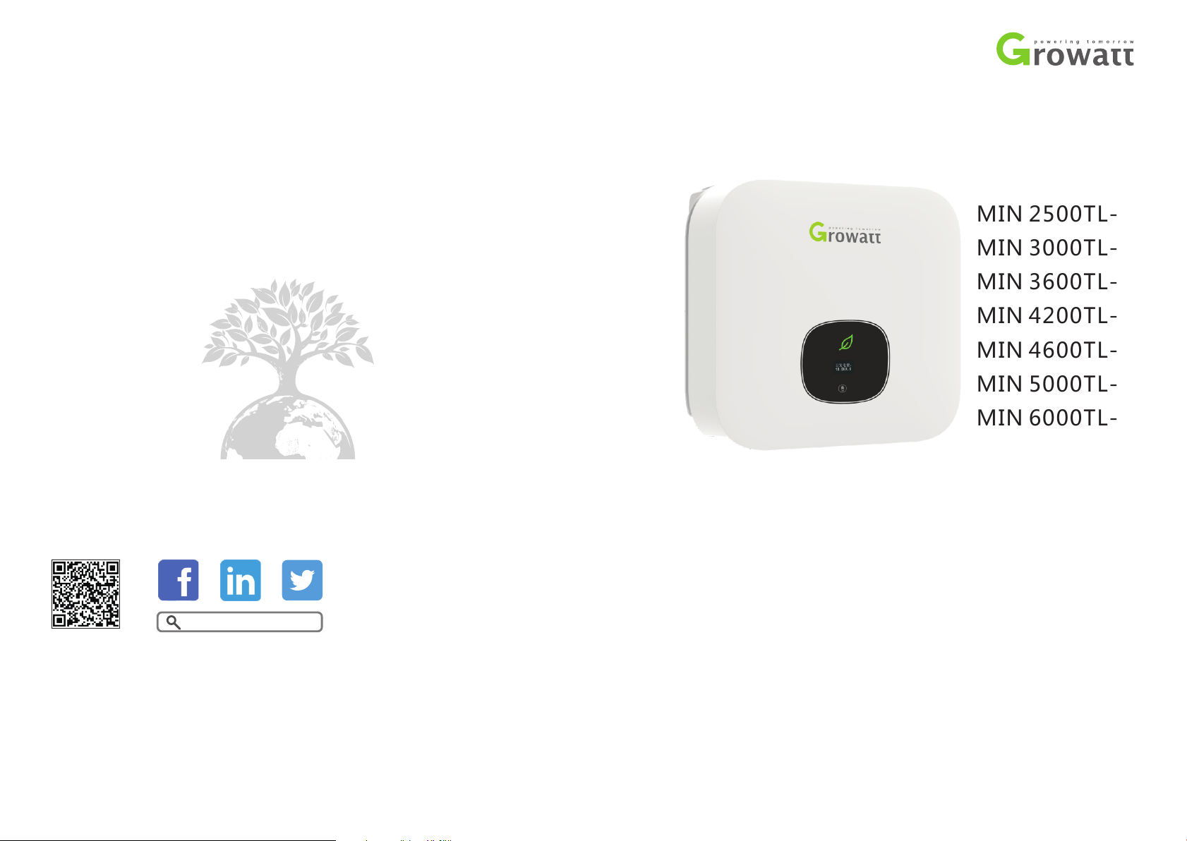
Growatt MIN 2500TL-X, MIN 3000TL-X, MIN 4600TL-X, MIN 3600TL-X, MIN 5000TL-X Installation & Operation Manual
...Page 1
Installation
MIN 2500TL-X
MIN 3000TL-X
MIN 3600TL-X
MIN 4200TL-X
MIN 4600TL-X
MIN 5000TL-X
MIN 6000TL-X
Growatt New Energy
Down lo ad
Manu al
Shenzhen Growatt New Energy Technology CO.,LTD
No.28 Guangming Road, Shiyan Street, Bao’an District,
No.28 Guangming Road, Shiyan Street, Bao’an District,
Shenzhen, P.R.China
Shenzhen, P.R.China
T
+86 0755 2747 1942 +86 0755 2747 1942
service@ginverter.comservice@ginverter.com
E
www.ginverter.comwww.ginverter.com
W
GR-UM-155 A-01-
&
Operation Manual
Page 2

Index
1 Notes on this manual
2 Safety
3 Product Introduction
1. 1 Valid it y
1. 2 Target G roup
1.3 Addi ti on al informatio n
1. 4 Symb ol s in this document
1. 5 Glos sa ry
2. 1 Inte nd ed Use
2. 2 Qual if ication of skille d pe rson
2.3 Safe ty i ns truction
2. 4 Asse mb ly War ni ngs
2. 5 Elec tr ical Connection Warni ng s
2. 6 Oper at ion Warn ings
3. 1 TL-X O ve rview
3. 2 Type lab el
3.3 Size a nd w ei ght
3. 4 Stor ag e of Inverter
3. 5 The ad va ntage of the unit
4 Unpacking and inspection
5 Installation
Safety i ns tr uctions
5.1
Select in g th e installatio n lo ca tion
5. 2
Mounti ng t he I nverter
5. 3
Page 3
6 Electrical connection
6. 1 Safe ty
6. 2 Wiring AC Outpu t
6. 3 Conn ec ting the second protect iv e
conduc to r
6. 4 Conn ec ting the PV Array(D C in put)
6.5 Conn ec ti ng signal cable
6.6 Grounding th e in verter
6.7 Acti ve p ow er control with smart
meter , CT o r ri pp le control signal
receiver
6.8 Inve rt er d emand response modes
(DRMS)
6.9 AFCI (O pt ional)
11 Trouble shooting
12 Manufacturer Warranty
11.1 Error Mes sa ge s displayed on
OLED
11.2 Sys te m fault
11.3 Inv er ter warni ng
11.4 Inv er ter fault
7 Commissioning
8 Start -Up and shut dow n
the inverter
9 Maintenance and Cleaning
10 EU Declaration of Conformity
7. 1 Star t th e inverter
7. 2 Gene ra l setting
7. 3 Adva nc ed setting
7. 4 Comm un ications
8. 1 Star t- Up the inverter
8. 2 Turn-off the Invert er
9. 1 Chec ki ng Heat Dissipati on
9. 2 Clea ni ng the Inverter
9. 3 Chec ki ng the DC Disconnec t
13 Decommissioning
13.1 Dis ma nt ling the Invert er
13.2 Pac ki ng t he Inverter
13.3 Sto ri ng t he Inverter
13.4 Dis po si ng of the Inverte r
14 Technical Data
14.1 Spe ci fi cation
14.2 DC &A C co nn ector info
14.3 Torque
14.4 Acc es so ries
15 Compliance Certificates
16 Contact
Page 4
1 Notes on this manual
1.1 Validity
This manual describe s the assembly, i ns tallation, commissio ni ng an d mai nt en ance of th e
follow in g Grow at t Inverter model:
MIN 2500 T L- X
MIN 3000 T L- X
MIN 3600 T L- X
MIN 4200 T L- X
MIN 4600 T L- X
MIN 5000 T L- X
MIN 6000 T L- X
This ma nu al does n ot cover any d et ails concerning equipm en t connected t o the MIN TL X( e. g. PV modul es ). Informati on concern in g the con ne cted equip me nt is avail ab le from
the manu fa ct urer o f the equipment.
CAUTIO N
NOTICE
Inform at io n
CAUTIO N in di ca tes a ha zard ous situation which, if not avoid ed ,
could result in mi no r or moderate injur y.
NOTICE i s us ed t o address practices not relat ed t o pe rsonal injury.
Inform at io n that you must read and know t o en sure o pt imal
operat io n of t he system.
1.2 Target Group
This manual is for qualifi ed perso nn el. Qualified per so nnel have received trainin g a nd
have demons tr at ed sk il ls an d knowl ed ge in th e constru ct ion a nd op er at ion o f this
device . Q ualified Perso nn el are t rained to deal w it h the dangers an d h azards involved in
instal li ng e lectric devic es .
1.3 Additional information
Find fur th er i nformation on s pe ci al topics in the do wn lo ad are a at www.ginverter.com
The manu al a nd o ther document s mu st b e stored in a convenient pl ac e and be available
at all tim es . We ass um e no liability for an y da mage caused by fail ure to o bs er ve these
instru ct io ns. For possibl e ch an ges in this manua l, G RO WATT NEW ENERGY
TECHNO LO GY C O.,LTD ac ce pt s no res ponsibilities t o in form the users.
1.4 Symbols in this document
1.4.1 Sy mb ol s in this documen t
A warn ing describes a h az ard to e qu ipment or personn el . It c alls attentio n to a p roce du re
or p ractice, wh ich, if not co rrec tl y perfo rm ed or a dhered to, could resul t in da ma ge to or
destru ct io n of part or all of the Growatt equipment and/or other equipment connec te d
to the Growatt equ ip ment or personal in ju ry.
Symbol descri pt io n
DANGER indicates a haza rdous situation which, if not av oided, w il l
DANGER
result in death or s er ious injury.
1.4.2 Ma rk in gs on this produc t
Symbol Explan at io n
Electr ic al v oltage!
Risk of fi re or expl os ion!
Risk of bu rns
Operat io n af ter 5 minutes
Point of c on ne ction for grounding protect io n
Direct Current (DC)
Alternating Current (AC)
Read the m an ua l
CE mark.
The inv er te r complies with th e req ui re me nt s of the applica bl e CE
guidel in es .
WARNING indic at es a hazardo us situation whic h, if not avoided,
WARNING
1
could result in de at h or serious injury.
The inve rt er m ust not be dispos ed o f wi th the househol d wa st e.
2
Page 5
1. 5 Glossary
AC
Abbreviation f or " Alterna ti ng C urre nt"
DC
Abbreviation f or " Dire ct C urre nt"
Energy
Energy is m easured in Wh (watt h ou rs), kW h (kilo wa tt hour s) or MWh (m egawatt h ours).
The en ergy is t he power calculated over time . For exa mp le, your inverter op erates at a
consta nt po wer of 4600 W for ha lf an hour and then at a c onstant powe r o f 2 300 W for
anothe r ha lf an hour, it has fed 345 0W h of energy int o th e power distr ib ut ion grid with in
that hou r.
Power
Power i s m easure d in W (wa tt s), kW (k il owatts) or MW (megawatts) . P ower is an
instan ta ne ous value. It displa ys th e power your inverter is cur rent ly fe ed ing into the
power di st ri bution grid.
Power ra te
Power rate is th e radio of c ur re nt power feeding into the po we r dis tr ib ution g rid and the
maximu m po we r of the inverter t ha t ca n feed into the pow er d is tribution gri d.
Power fa ct or
Power factor is the ra tio of true powe r or wa tt s to ap pare nt power or volt amps. Th ey are
identi ca l only wh en curren t and v ol ta ge are in p ha se than t he power fa ctor is 1 .0. The
power in an ac ci rc ui t is very s eldom equ al to the d irec t prod uct of th e volts and a mperes.
In order to f in d th e powe r of a single phase ac circ uit the prod uc t of volts and amperes
must be mu lt ip lied by the power f ac to r.
PV
Abbreviation f or p hotovoltaic.
Wirele ss c om munication
The exte rnal wireless commu ni ca tion technolo gy i s a ra dio technolog y th at a llows the
invert er a nd o ther communic at io n prod ucts to communica te w ith each other. The
external wireless communi ca ti on does not require line of sight b et we en the devices and
it is sele ct iv e purc hasing.
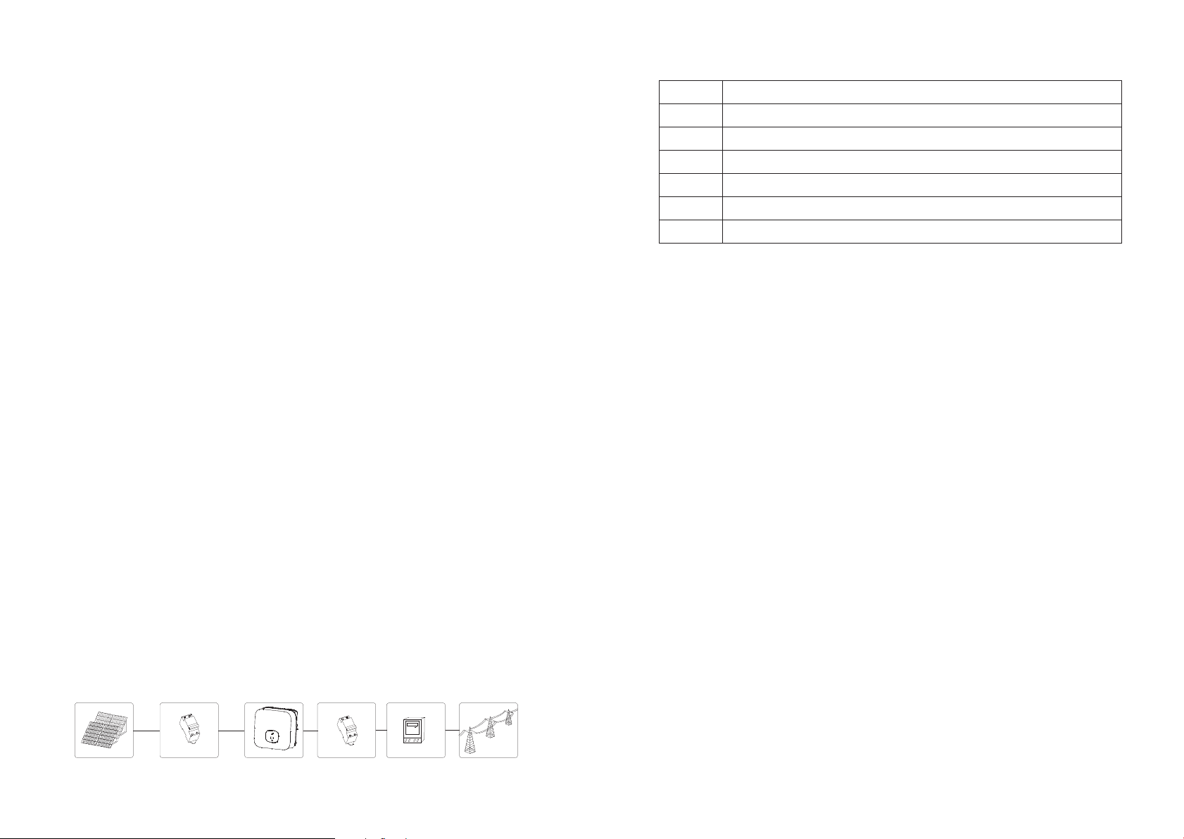
2 Safety
2. 1 Intended Use
Positi on D escription
A
B
C
D
E
F
The inverte r may only be operated with a permanent connection to the public power
grid. The inv er ter is not int ended for mobile use. Any other or additional use i s not
consid ered the inte nd ed use. The manu fa cturer /supplier i s not l iable f or damage c aused
by suc h un intended use. D am age caused by s uc h unintende d us e is at the sol e ri sk of the
operat or.
PV modul es C ap acitive Disch ar ge C urrents
PV modules with large capacities relative to earth, such as thin-fi lm PV modules with
cells on a meta ll ic substrate, may only b e used if their coup li ng capacity d oes not e xc eed
1uF. During fe ed -in operation , a leakage current flo ws f ro m the cells to ea rt h, the size o f
which d epends on t he manner i n which t he PV modul es are installe d (e.g. foi l on metal
roof) and on t he weather (r ai n, snow). T hi s "normal" le ak ag e current may n ot e xceed
50mA due to the fact tha t the i nverter would ot he rwise au to matically disconnect fro m
the elec tr ic ity grid as a protective me as ure.
PV modul es
DC load ci rcuit breake r
Invert er
AC load ci rcuit breake r
Energy m et er
Utilit y gr id
2. 2 Qualification of skilled person
This g ri d-tied invert er sys te m operates on ly whe n prop er ly c onnected to t he A C
distri bu ti on network. Before connecting the MIN TL-X to the power distribution grid,
contac t the l ocal pow er distrib ut ion grid company. This connection must be made o nly
by quali fi ed t echnical person ne l to c onnect, and only afte r receiv in g ap prop ri ate
approvals, as required by the lo ca l authority havin g ju risdiction.
The uni t c on verts the DC curren t g enerated by the photovo lt aic (PV) modules to gridcompli an t alter nating current and perf or ms si ng le-phase feed-in i nto the elec tr ic ity
grid.M IN 2500TL -X ,MIN 3000TL-X, MI N 360 0T L-X,MIN 4200TL-X,MIN 4600TL-X ,M IN
5000 TL-X , MI N 6000T L- X inverte rs are bu il t according to a ll required saf et y rules .
Nevert he le ss, improper use may cause let ha l h az ards fo r t he operator or third parties, or
may result in dama ge t o the units and other p rope rt y.
Princi pl e of a P V plant with this M IN T L- X single-phas e in ve rter
A
3
B
C D E
2. 3 Safety instruction
The MIN T L- X Inv er ters is designed and tested a cc ordi ng to internat io na l saf et y
requirements(IEC621 09 -1,CE,VDE0126 -1 -1, A S4 777,etc); however, certain sa fe ty
precautions must be observed when installing and operating this inverter. Read and
follow all instructions , cau ti ons a nd war nings i n t hi s i ns tallation manual. If q uestions
arise, p le as e contact Growatt's tec hn ical services at +8 6 (0 )755 2747 1900.
F
4
Page 6
2. 4 Assembly Warnings
ØPrior to i ns ta llation, insp ec t th e unit to ensure absence of a ny
transp or t or h andling damag e, w hi ch could affect insulat io n
integr it y or s afety clearan ce s; f ailure to do so could result in
safety h az ards .
ØAssemb le t he i nverter per the i ns tr uctions in this m an ua l. Use care
when cho os in g installatio n lo ca tion and adhere to specif ie d
coolin g requiremen ts .
ØUnauth or iz ed rem oval of necessary p rote ct io ns, improper use,
WARNING
incorrect inst al lation and operat io n may lead to serious s af ety
and shoc k ha za rd s an d/or equipment da ma ge.
ØIn order to minimi ze t he potential of a sho ck h azard du e to
hazardous volt ag es, cover the entire sola r ar ra y with dark
materi al p ri or to connectin g th e ar ray to any equipm en t.
ØGrounding the PV mo dules:The MIN TL-X is a transformerles s
invert er. Tha t is wh y it ha s no ga lv anic se pa ra tion. D o not g roun d
the D C circuits o f the PV m od ules con ne cted to the MIN TL-X.
Only g roun d th e mounting fr ame of the PV mod ul es .If you
connec t groun de d PV modules to the MIN TL-X, t he error
messag e "P V IS O Low".
ØComply with the local req uire ments for grou nd in g t he PV
CAUTIO N
mod u l e s and t h e PV ge n e rato r. G R OWAT T recom m e n ds
connec ti ng the gene ra tor frame a nd other el ec tr ically co nd uc tive
surfac es in a manner w hich ens ures continuous conduction with
ground in order to have optimal prot ec tion of t he s ystem and
person ne l.
2.5 Electrical Connection Warnings
ØThe comp on en ts in the inverte r are live . Touc hing live compone nt s
can result in seri ou s injury or death.
Do not ope n th e in verter except t he w ire bo x by q ualified person s.
Electr ic al i nstallation , repair s an d conversions may o nl y be carried
out by ele ct ri cally qualifi ed p er sons.
Do not tou ch d am aged inverter s.
ØDanger t o li fe d ue to high voltag es i n th e inverter
There is residual volt ag e in t he inverter. Th e inverter takes 20
DANGER
minute s to i sc harge.
ØPerson s wi th l imited physic al o r me ntal abilitie s ma y on ly work
with the G rowatt i nv erter following p rope r in st ruction and und er
consta nt s up ervision. Chi ld ren are forb id de n to play with the
Growatt invert er. Must keep the G rowatt i nv erter away from
children.
ØMake all e le ct rical connect io ns ( e.g. conducto r te rm ination,
fuses, P E co nn ection, etc.) i n ac co rd an ce with prevailing
regulations. W he n working with the in ve rter powered on, adhere
to all prevailin g sa fety reg ulations to min im iz e risk of acciden ts .
ØSystem s with inverters t ypically re qu ire additiona l control ( e. g.,
WARNING
switch es , dis co nn ects) or p rotect iv e dev ic es (e .g ., fu si ng ci rcui t
breakers) depe nd ing upon the prevailing s af et y rules.
2.6 Operation Warnings
ØEnsure all conne ct ors are se aled and secure during op er ation.
ØAlthou gh designed to meet al l safety requ irem en ts , some parts
and surfaces of I nv erter are still hot d ur ing op er ation. To reduce
the risk o f injury, do no t touch the heat si nk a t the back of t he P VInvert er o r ne arby surfaces w hi le I nverter is oper at in g.
ØIncorrect si zi ng of the PV pl ant may result in v ol tages being
present which c ou ld dest roy the inv er ter. The inv er te r displ ay will
read the error message “ PV v ol tage High!”
WARNING
CAUTIO N
ØTurn the rotary swi tc h of the DC Disco nn ect to the Off positi on
immedi at el y.
ØContac t in st aller.
Turn the rot ar y s witch of the DC Disconnect to the Off p os ition
immedi at el y.
Contac t in st aller.
ØAll oper at io ns reg ardi ng t ransport, ins ta ll ation and start -u p,
includ in g ma intenance mus t be o pe rated by qualif ie d, t rained
person ne l an d in compliance w it h al l prev ailing codes and
regulations.
ØAnytim e th e in verter has been d is co nnected from the power
networ k, u se e xtre me caution as some co mp onents can retain
charge s uffici en t to cre at e a shock hazard; to minimi ze
occurrence of su ch c onditions, comp ly w ith all corresponding
safety s ym bo ls and markings p resent o n th e unit and in this
manual .
ØIn speci al c as es, there may still be inte rf eren ce f or the specifie d
applic at io n area d espite maintain in g standardized emissi on l im it
values ( e. g. w hen sensitive e qu ip ment is located a t th e se tup
locati on o r wh en the setup loca ti on i s near radio or tel ev is ion
receivers).I n th is case, the operat or i s obliged to take proper
action t o rectif y th e situation.
ØDo not stay close r than 20 cm to the inv er te r for any length o f
time.
5
6
Page 7
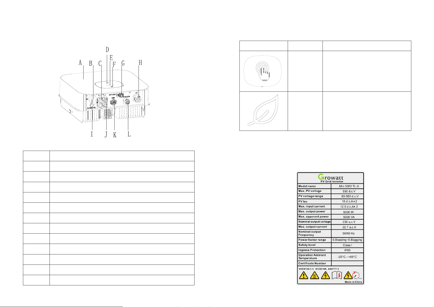
3 Product description
A
B
C
D
E
F
G
H
I
J
K
L
3.1 TL-X Overview
Symbol o n th e in verter
Positi on Descri pt io n
COVER
DC SWITC H
PV INPUT +
Symbol
Descri pt io n Explan at io n
Touch symb ol
Invert er s ta tus
symbol
Touch butt on .We ca n sw itch the OLED
displa y an d se t parameter by to uc hi ng.
Indica te s in verter operat io n st atus:
Red:Fa ul t.
Green:Nomal.
Red leaf f la sh :War ning or DSP Programming.
Green leaf flash :M 3 Prog ra mming.
3.2 Type label
The type l ab el s prov ide a unique identi fi cation of the inver te r (The type of product,
Device -s pe cific charact er is tics, Certifi ca te s and approvals). The typ e la bels are o n the
left-h an d si de of the enclosu re.
LED
OLED
TOUCH BU TT ON
DRM PORT ( Au stralia or EU)
AC OUTPU T
VENTIL ATION VA LVE
PV INPUT-
USB PORT
COM PORT
7
8
Page 8
More detail abou t th e type label as the cha rt b elow:
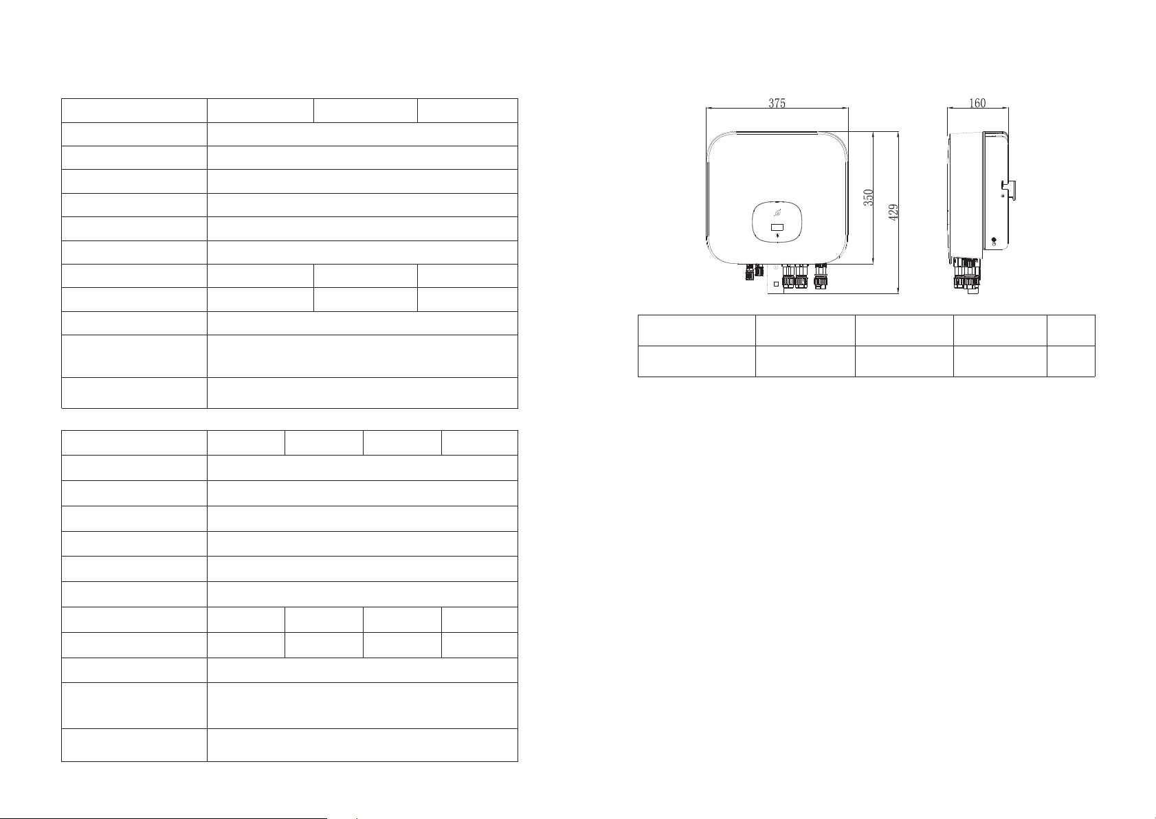
3.3 Size and weight
Model Na me
Max inpu t DC v ol tage
Max inpu t DC c ur re nt
Start vo lt ag e
MPP volt ag e ra nge
AC nomin al v ol tage
AC grid frequenc y
Max. app arent po we r
AC norma l ou tp ut current
Power fa ct or
Environmenta l
Protection
Rating
Operat io n Am bient
temper at ure
Model Na me
Max inpu t DC v ol tage
Max inpu t DC c ur re nt
Start vo lt ag e
MPP volt ag e ra nge
AC nomin al v ol tage
AC grid frequenc y
MIN 2500 T L- X MIN 3000 T L- X MIN 3600 T L- X
500V
12.5A/ 12 .5 A
100V
80V~50 0V
230V
50/60 Hz
2500VA 3000VA 36 00 VA
18.8A 13A 15.6A
0.8lea di ng …0.8lagging
IP 65
- 25...+60℃ ( -1 3...+ 140°F)
with der at in g above 45°C( 113°F )
MIN 6000MIN 5000MIN 4600MIN 4200
TL-XTL-XTL-XTL-X
550V
12.5A/ 12 .5 A
100V
80V~55 0V
230V
50/60 Hz
Model
MIN 2500 -6 00 0 TL-X
Height ( H) Wi dth (W) Depth ( D)
350mm 13 .8 in ch 375mm 14 .8 in ch 160mm 6. 3i nc h 10 .8 kg
Weight
3.4 Storage of Inverter
If you want to stor ag e t he inve rt er in your warehouse, you should choose an ap prop ri ate
locati on t o st ore th e inverter.
ØThe unit m us t be s tore d in original packa ge a nd desiccant must b e le ft in the
packag e.
ØThe stor ag e te mperature should be alw ay s between -25℃and +60℃. A nd t he
storag e relati ve h umidity can achie ve t o 100%.
ØIf there are a batch of inve rt er s need to be stored, the maxi mu m layers for origin al
carton i s fo ur.
ØAfter lo ng t er m storage, loca l in st aller or servic e de pa rtment of GROWATT s ho ul d
perfor m a co mp re he nsive test before insta ll at ion.
Max. app arent po we r
AC norma l ou tp ut current
Power fa ct or
Environmenta l
Protection
Rating
Operat io n Am bient
temper at ure
9
4200VA
18.2A
with der at in g above 45°C( 113°F )
4600VA
20A 21.7A 26A
0.8lea di ng …0.8lagging
IP 65
- 25...+60℃ ( -1 3...+ 140°F)
5000VA 6000VA
3.5 The advantage of the unit
ØMaximu m effici en cy of 98.4%
ØWi de input voltage ra ng e from 8 0- -550Vdc
ØReacti ve p ow er reg ulate
ØIntegr at ed D C switch
ØMulti MP P co nt ro ll er
ØDSP cont roller
ØTouch cont rol
ØMulti ac ti ve p ower control mode
ØEasy ins ta ll ation
10
Page 9
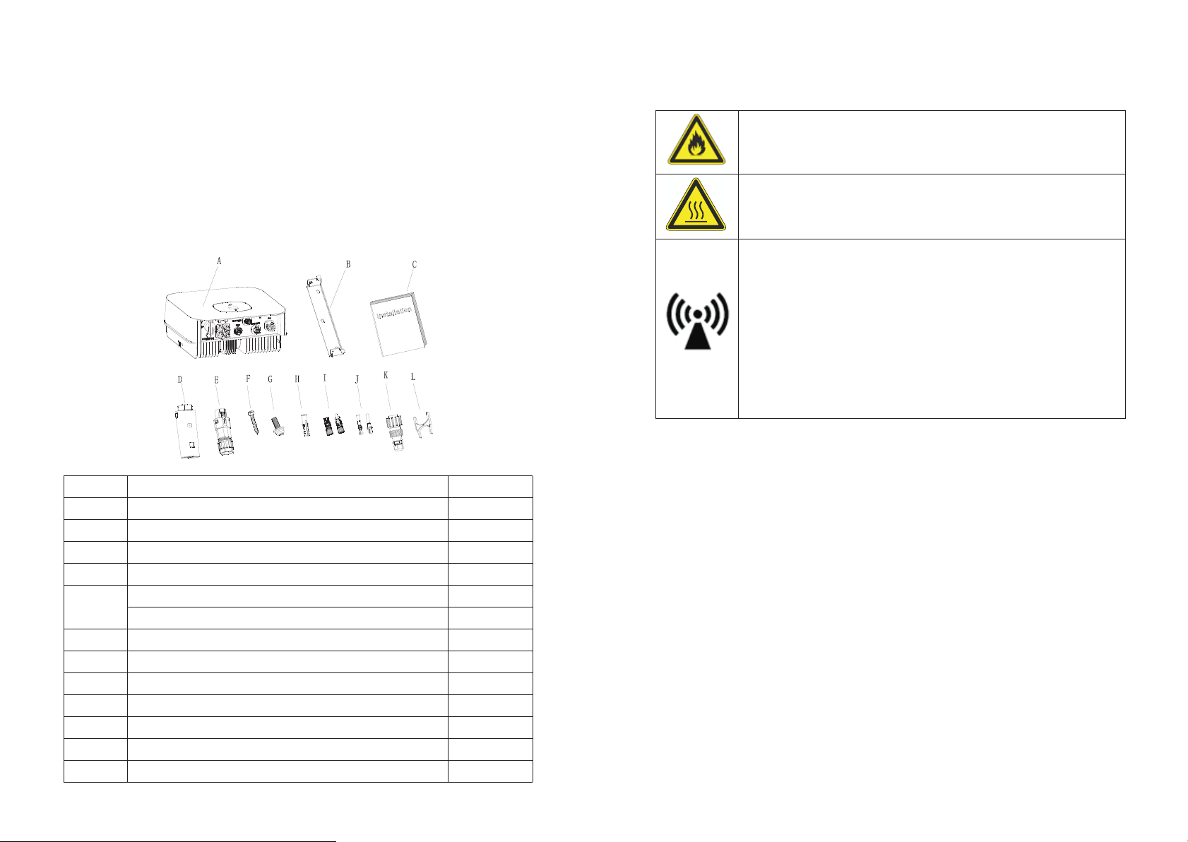
4 Unpacking and inspection
The inver te r is thoro ug hly tested and inspe ct ed strictly before delivery. Our inverters
leave o ur factory in proper e lectrical and mech an ical condi ti on. Spec ia l packag in g
ensures safe a nd ca re fu l transportati on . H owever, tr an sport damage ma y s ti ll occur. T he
shippi ng co mp an y is respons ib le in such case s. Th orough ly in sp ec t the in ve rter upon
delive ry. Immediately not if y th e respon si ble shipping company if you disco ve r an y
damage to t he pa ck aging w hi ch in di cates t ha t the inverter may have be en da ma ged o r if
you discover any visible damage to th e inver te r. We will be g la d to assist you, if required.
When t ra ns porting the i nv erter, th e original or e qu ivalent packa gi ng should be us ed , and
the maxi mu m la yers for origin al c ar ton is four, as t hi s ensures safe transpor t.
After openin g th e pack ag e, p lease check the contents of the box. It should contain the
follow in g, Pl ease check all of the access or ies c aref ully in the carton. If anythin g m is sing,
contac t yo ur d ealer at once.
Object
A
B
C
D
E
F
G
H
I
J
K
L
11
Descrip ti on
Invert er
Mounti ng b ra cket
Quick Gu id e
Monito r( Op tional)
Signal c on ne ctor
DRM PORT(A us tralia or EU)
Self-t ap pi ng screws
Safety- lo ck s crew
Plasti c ex pa nsion pipe
PV+/PV- t er minal
PV+/PV- m et al terminal
AC conne ct or
Uninst al l si gnal and AC conne ct or t ool
Quanti ty
1
1
1
1
1
1
3
1
3
2/2
2/2
1
1
Installation 5
5.1 Safety instructions
Danger t o li fe d ue to fire or explo si on
Despit e ca refu l co nstruction, ele ct rical devices can c au se fires .
Do not i nstall the inverter on ea sily flammable materials and w here
flamma bl e ma terials are stored.
Risk of bu rn s du e to hot enclosur e pa rt s
Mount the inve rt er i n su ch a w ay t ha t it c an no t be t ou ched
inadve rt en tly.
Possib le d am age to health as a result of th e effe ct s of r adiation!
In speci al c as es, there may still be inte rf eren ce f or the specifie d
applic at io n area d espite maintain in g standardized emission l im it
values ( e. g. w hen sensitive e qu ip ment is located a t th e se tup location
or when th e se tu p location is nea r ra di o or television receive rs ).In this
case, th e op er ator is obliged t o ta ke p ro pe r action to rectify the
situat io n.
Never in st al l the inverter ne ar t he s ensitive equi pm en t(e.g. Radios,
teleph on e, t elevision, et c)
Do not sta y cl os er than 20 cm to the in ve rt er for any length o f ti me
unless i t is a bs olutely neces sa ry.
Growatt assu me s no responsibility f or compliance t o EMC regulations
for the co mp le te system
ØAll elec tr ic al installati on s sh all be done in acco rdance w it h the local and natio na l
electr ic al c odes. Do not remove the cas in g. Inverter conta in s no user serviceab le
parts. R ef er s ervicing to qua li fi ed service pers on ne l. all wiring and e le ct rical
instal la ti on should be cond uc te d by a qualified se rv ic e personnel .
ØCarefully remove the u ni t from i ts p ackaging and insp ec t for exter na l da mage. If you
find any i mp er fections, ple as e co ntact your loca l de al er.
ØBe sure that the inv er ters connect to the g roun d in o rder t o protec t prop er ty a nd
person al s af ety.
ØThe inve rt er m ust only be opera te d wi th PV generator. Do not connect any ot he r
source of energy t o it .
ØBoth AC an d DC v ol tage sources are terminated i ns id e the PV Inverter. Please
discon ne ct t hese circuits before servic in g.
ØThis uni t is d es igned to feed pow er t o th e public power gr id ( ut ility) only. Do n ot
connec t th is u nit to an AC source or genera to r. Connecti ng I nv erter to external
device s co ul d re su lt in serious damag e to y our equipment.
ØWhen a pho to vo ltaic panel is ex po se d to light, it gene ra te s a DC voltage. Whe n
connec te d to t his equipment , a ph ot ovoltaic pane l wi ll c harge the DC link
capaci to rs .
ØEnergy s to red in t hi s equipment's DC li nk c apacitors presents a ri sk o f el ectric shock.
Even aft er t he u nit is disconne ct ed f ro m th e grid and photovol ta ic panels, high
voltag es m ay s till exist insi de t he P V-Inverter. Do n ot rem ove the casing unti l at l east
5 minute s af te r disconnecti ng a ll p ower sources.
ØAlthou gh d es igned to meet all s af et y re qu irem en ts, some parts an d su rf aces of
Invert er a re sti ll h ot during operati on . To red uc e th e risk of injury, do not touch the
heat sin k at t he b ack of the PV-Inve rt er or nearby surfac es w hi le Inverter is
operat in g.
12
Page 10

5.2 Selecting the installation location
ØThis is guidanc e for ins ta ller to choose a suitable in stallation location, to avoid
potent ia l da mages to device a nd o pe rators.
ØThe installa ti on l ocation must be suitable for the inverter 's wei gh t an d di me nsions
for a long p er io d time.
ØSelect t he i ns tallation loc at io n so that the statu s di sp lay can be easily v ie we d.
ØDo n ot install the inverter on structures con st ructed of flammable or thermolabile
materi al s.
ØNever install the i nverter in environment of lit tl e or no air flow, nor dust
environment. T ha t may derate the efficien cy o f th e cooling fan of th e in ve rter.
ØThe I ng re ss Protection r at e is IP65 which means the inve rt er can be installed
outdoo rs a nd i ndoors.
ØThe humi di ty o f the installat io n lo cation should b e 0~ 10 0% without cond en sa tion.
ØThe inst al la tion location m us t be f re el y and safely to get at al l ti mes.
ØVertica ll y installat io n and make sure the connec ti on of inver te r must be d ownwards.
Never in st al l horizontal an d av oi ds forward and sideways t il t.
Ambien t di me nsions of one inv er te r
Ambien t di me nsions of serie s in ve rters
ØThere mu st be sufficient clearance between t he individual inverters t o ensure th at
the cool in g ai r of the adjacent i nv er ter is not taken in .
ØIf necessa ry, increase t he c learance spaces and mak e sure there is enough fresh air
supply t o en su re s uffi ci en t cooling of the in ve rt ers.
The inver te r can't install to sola ri za tion, drench, firn loc at ion. We suggest that the
invert er s sh ould be install ed a t th e location with s om e co ver or protection.
ØBe sure that the inv er ter is out of the child ren' s reach.
ØDon't pu t an y th ings on the inver te r. Do not cover t he i nv erter.
ØDo not ins ta ll t he inverter nea r te le vision antenn a or a ny o ther antennas a nd
antenn a ca bl es.
ØInvert er requi res ad eq ua te cooling spac e. P rovi di ng better ventila ti on for the
invert er t o en sure t he heat escape adeq ua tely. The amb ie nt temperature should be
below 40 °C t o en sure o ptimum operatio n.
ØDo not exp os e th e inverter to direct sunl ig ht, as this can cause e xc essive heating an d
thus pow er reduc ti on.
ØObserv e th e Mi n. clearances t o wa ll s, other invert er s, o r objects as show n be lo w:
13
14
Page 11

ØPlease m ak e su re t he i nverter is instal le d at the right place. Th e inverter can't in st all
close to t ru nk .
5.3 Mounting the Inverter
5.3.1 Mo un ti ng the Inverter w it h br acket
In order to avoid elec tr ic al shock or other injur y, inspect existi ng
electronic or pl um bing installati on s before d rilling holes .
DANGER
5.3.2 Fixed the inverter on the wall
Fallin g eq ui pm ent can cause serious or even fatal injur y, n ev er
mount the i nv erter o n the b racket un less yo u are sure th at the
mounti ng frame is rea ll y firmly mo unted on th e wall af te r carefully
WAR NI NG
ØRise up the inve rt er a l it tle higher than the bracket . Co ns idered t he w ei ght of
them.D ur in g the process please main ta in the balance of the i nv erter.
Hang the i nv er ter on the bracke t th roug h th e match hooks on brac ke t.
checki ng .
Fix the mounti ng br ac ket a s t he fi gure sh ow s. Do no t m ak e t he sc rews to be flush to
the wall . In st ead, leave 2 to 4mm e xp os ed.
15
Ø A fter c on firming the inverter is fixed reliably, fasten one M6 s afety-lock sockets
head cap screws on the right or left side firmly to prevent the invert er f rom being
lifted o ff the bra ck et.
16
Page 12

6 Electrical connection
Decisi ve Vo ltage Class (DVC) i nd ic ated for ports
Port Nam e
AC
DC
Class
The AC wir in g st ep:
1.Unin st al l the parts of the AC c on ne ction plug from the acces so ry bag.
C
C
DRM
RS485& US B
6.1 Safety
Danger t o li fe d ue to lethal volt ag es !
High voltage s w hi ch may cause electric shock s a re present in the
conduc ti ve parts of th e inv er ter. Prior to perf or ming an y w or k o n
the inve rt er, disconn ec t th e inverter on the A C an d DC s ides
Danger o f da ma ge to electronic compon en ts due to electrostatic
discha rg e.
Take ap prop ri ate ESD pre ca ut ions whe n rep lacing and installing
WAR NI NG
the inve rt er.
6.2 Wiring AC Output
ØYou must insta ll a separat e sing le -p hase c ircu it-bre aker o r ot he r
load disconnecti on unit for e ac h invert er in ord er to ensure that
the inve rt er c an be safely disc on ne cted under load .
NOTE :
The inverter has the fun ction o f detecti ng resid ua l current and
WAR NI NG
protecting the inve rt er agains t residual cu rren t. If y ou r inver te r has t o
equip a AC bre aker which ha s the functio n of detecting resi du al
current ,yo u m ust choose a AC brea ke r with th e rating resi du al
current more than 300m A.
A
A
2.Inse rt t he s tripped and bared cable t hrou gh p ress ure screw, seal r in g, t hrea ded sleeve
in seque nc e, i nsert cables in to c on nection termi na l ac cord ing to polarities i nd icates on
it and tig ht en t he screws firmly. Ple ase try to pull out the w ire to mak e su re t he i t’s we ll
connec te d.
You m us t install a se pa rate single- ph as e circuit-breaker or oth er load disconn ec ti on unit
for each in verter in order to ensure th at th e inverte r can be s af el y dis co nn ected u nder
load.
We suggest you cho ic e the AC bre aker rating cur rent in th is t able:
MIN 2500 T L- X
MIN 3000 T L- X
MIN 3600 T L- X
MIN 4200 T L- X
MIN 4600 T L- X
MIN 5000 T L- X
MIN 6000 T L- X
17
16A/23 0V
16A/23 0V
20A/23 0V
25A/23 0V
25A/23 0V
32A/23 0V
32A/23 0V
18
Page 13

3.Push t he t hrea de d sleeve into the soc ke t, Tigh te n up t he cap on the termi na l.
5.To remove the AC con ne ctor, press the bayon et o ut of the slot with a sma ll s crew dr iver
and pull i t ou t, or unscrew the threaded sleev e, th en pull it out.
The Inverter Side
Unlock the housing
4.Fina ll y, Push or screw the threaded sleeve to con ne ct ion terminal unti l b ot h a re lock ed
tightl y on t he i nverter.
Lock the housing
Lock the housing
Wi re s ug ge stion length
Conduc to r cros s
sectio n
4 mm² 12AWG
5.2 mm² 10 AWG
Conduc to r cros s
sectio n
5.2 mm² 10 AWG
Unlock the housing
MIN 2500 T L- X
48m
60m
MIN 4200 T L- X
MIN 4600 T L- X
28m
The Inverter Side
Max. cab le l en gth
MIN 3000 T L- X
40m
50m
Max. cab le l en gth
MIN 5000 T L- X
26m
MIN 3600 T L- X
33m
42m
MIN 6000 T L- X
24m
19
Lock the housing
6.6 mm² 9AWG
36m
33m
30m
20
Page 14

6.3 Connecting the second protective conductor
In some in st al lation countr ie s, a s econd protective cond uc tor is req uire d to p re ve nt a
touch cu rrent in t he e vent of a malfuncti on i n the original protecti ve c on ductor.Fo r
instal la ti on countries fa ll in g within the scop e of v al idity of the IEC st an da rd 6 21 09, you
must ins ta ll t he pro tective conduct or o n the AC terminal wit h a co nductor cross-section
of at leas t 10 m m² Cu.Or Install a s ec on d prot ective conducto r on t he earth terminal w it h
the same c ross-s ec tion as the origina l prot ec ti ve conductor on t he A C te rminal. This
prevents touch c ur re nt i f th e original protective c on ductor fails.
CAUTIO N
If the i nverter is no t equipped wi th a DC swi tc h but this is m andatory in
the coun tr y of i nstallation , in st all an extern al DC switch.
The followin g limi t valu es at the DC input of t he i nv erter must not b e
exceed ed :
Types
2500-3 00 0 TL -X
Max current PV1
12.5A 12.5A
Max current inpu t B Ma x vo ltage
500V
6.4 Connecting the PV Array (DC input)
6.4.1 Co nd it ions for DC Conne ct io n
The sola r mo du les connected t o th e in verter must con fo rm t o the
Class A requirements o f th e IE C 61730 standard.
WAR NINGWAR NING
The MIN TL -X s in gle-phase inv er te r has 2 independe nt i np ut : PV1 & PV2
Notice t ha t th e connectors are in paired (mal e an d fe male connecto rs ). T he
connec to rs f or PV arrays and in ve rt ers are VP-D4 connector s;
21
3600-6 00 0 TL -X
6.4.2 Co nn ec ting the PV Array ( DC i np ut)
Danger t o li fe d ue to lethal volt ag es !
PV array su pplies d .c v ol ta ge to inverter when exposed to li gh t,before
conn ecting the PV array, c onver some li ght screens a bove PV
arrays ,e ns ure th at t he D C sw itch and AC brea ker are di sc onnect from
DANGER
WARNIN GWARNIN G
the inverter. NEVER connect or disco nn ect the DC connect or s under
load.
Make sure the maxi mu m open circuit voltage( Voc ) of e ach PV string
is less th an t he m aximum input vo lt ag e of the inverter.
Check the d es ign o f the P V plant . The Max. o pe n circuit voltage, which
can occur at s ol ar pa ne ls te mp erature o f -10℃ , mu st no t excee d the
Max. inp ut v ol tage of the inver te r.
Improper op er ation during th e wiring process c an cause fa ta l injury to
operat or o r un re co ve rable damage to the inv er ter. Only qua li fi ed
person ne l ca n perform the wir in g wo rk.
Please d on ’t con ne ct PV array positiv e or n egative pole to the g roun d,
it could
cause se ri ou s damages to the in ve rt er
Check th e connection ca bles of the P V modules for c orre ct polarity a nd
make sure that the maximum in pu t vol ta ge of th e inv er ter i s not
exceed ed .
12.5A 12.5A
550V
22
Page 15

Connec ti on o f PV terminal
Step 2 Pus h th e th re ad ed sleeve into the so ck et, Tig ht en u p the cap on the term in al .
6.5 Connecting signal cable
This ser ie s inverte r has o ne 8 Pin signal co nn ector(There a re two con ne ctors f or
AS/NZS 47 77 m odel ) . Signal Cab le P or ts:
Proced ur e
Step 1 Insert th e stripped and bared c ab le thro ug h pressure screw, se al ring, threaded
sleeve i n sequenc e, insert cab le s into co nn ection term in al according to number
indica te s on it and tighten the screws firmly. Please try to p ul l out the wire to
make sure the it's w el l connected.
Step 3 Push th e threaded sl ee ve to c on nection te rm inal until both are lo ck ed tightly on
the inve rt er.
Uninst al l si gnal connecto r
Step 1 Press the fas te ners and pull it out from the i nv er ter.
23
24
Page 16

Step 2 Ins er t th e H type tool and pul l it o ut f ro m th e socket.
Active p ow er c ontrol with a Radio Rippl e Co ntro l Re ceiver(RRCR ).
6.6 Grounding the inverter
The inve rt er must be connecte d to t he AC grou nding conductor o f th e power distrib ut io n
grid via t he g roun d te rminal (PE) .
Becaus e of the trans fo rmerless design, the DC positive pole and DC
negati ve p ol e of PV arrays are not permit te d to be grou nded.
WARNING
6.7 Active power control with smart meter , CT or ripple control
signal receiver
The po si tion of e xp ort limitat io n CT or M et er must b et we en the
Invert er & L oa d and gird.
Inform at io n
This series i nv er ter has integrated export l im itation functionali ty. To use this f un ction,
you can connect sma rt me te r o r CT. The smart mete r mod el is East ron SDM23 0- Modbus.
The CT Mo del i s TOP 90-S10 /S P4(LEM).The prim ar y apert ure is 10mm,output cabl e
length i s 5m . T he a rrow o n the CT must pointin g to ward s th e inverter.
6.8 Inverter demand response modes (DRMS)
This serie s inve rt er h as t he f un ction of d emand re sponse modes, We u se 8 Pi n so cket a s
invert er D RM S connection.
DRMS app li ca tion descript io n
ØApplic ab le to AS/NZ S4 777.2:2015 or Commission Regulation
Infor ma tio n
CAUTI ON
WAR NI NG
6.8.1 8P in s oc ket pin assignm en t
Pin No.
1
2
3
4
5
6
7
8
Assign me nt f or inverters ca pa bl e of both chargin g an d di scharging
(EU) 201 6/ 63 1.
ØDRM0, DR M5 , DR M6, DRM7, DRM8 are availa bl e.
Damage t o th e in verter due to moi st ure an d du st penetration
ØMake sure the cabl e gl and has been tighte ne d firmly.
ØIf the cab le g la nd are n ot m ounted properly, th e in verter can be
destroyed due to m oi sture and dust penetr at io n. Al l the warran ty
claim wi ll b e in valid.
Excess iv e vo ltage can damag e th e in verter!
External voltage of DRM P OR T don't over +5V.
DRM 5
DRM 6
DRM 7
DRM 8
RefGen
Com/DR M0
NC
NC
25 26
Page 17

6.8.2 Me th od o f asserting dem an d re sponse modes
1 2 3 4 5 6 7 8
K1
K2
K3
K4
6.8.3. 2T he i nverter is preconfigu red to t he f ol lowing RRCR pow er l ev els:
Mode
DRM 0
DRM 5
DRM 6
DRM 7
DRM 8
Soc k et As s erte d
by short in g pi ns
5
1
2
3
4
6
5
5
5
5
Operat e th e di sconnection d ev ic e
Do not gen er at e power
Do not gen er at e at more than 50% of rated pow er
Do n ot generate a t more than 7 5% of rated power AND
Sink reactive po we r if capabie
Increase p ower gene ra ti on (subje ct to c on st raints from
other ac ti ve D RMs)
6.8.3 Us in g th e Power Control I nt er face for EU
PRCR
DRM sock et
Invert er – R RC R Connection
Functi on
Pin 1
Short ci rcuit
with Pin 5
Pin 2 Pin 3 Pin 4
Short ci rcuit
with Pin 5
Short ci rcuit
with Pin 5
Short ci rcuit
with Pin 5
Active p ow er
0%
30%
60%
100%
Cos(φ)
1
1
1
1
Active p ow er c ontrol and rea ctive power con trol are enabled s ep arately.
6.9 AFCI Optional)(
6.9.1 Ar c- Fa ult Circuit Int er ru pter (AFCI)
In accordance wi th t he National Elect ri cal Code R, Article 6 90 .11, the inverter h as a
system f or t he rec og nition of electri c arc de te ct ion and interru pt io n. An electric arc
with a pow er o f 30 0 W or gre ater must be interr up ted by the AFCI withi n th e time
specif ie d by U L 1699B. A trippe d AF CI c an only be reset manually. You can dea ct iv ate
the auto ma ti c arc fa ult detection and i nt erruption (AFCI ) vi a a communication p roduct
in "Inst al le r" mode if you do not require the fun ct io n. The 2011 editi on o f th e National
Electr ic al C ode R, Section 69 0. 11 s tipulates tha t ne wl y installed PV sy st em s attached to
a buildi ng m us t be fitted with a me an s of d etecting and di sc on necting seria l el ec tric
arcs (AFCI) on the P V si de.
6.9.2 Da ng er i nformation
6.8.3.1 The following table describes the connector pin assignment and function:
DRM Sock et P in N O. Descri pt io n
27
Connec t to R RC R
1
2
3
4
5
6
7
8
Relay co nt ac t 1 input
Relay co nt ac t 2 input
Relay co nt ac t 3 input
Relay co nt ac t 4 input
GND
Not conn ec te d
Not conn ec te d
Not conn ec te d
K1 – Relay 1 o ut pu t
K2 – Relay 1 o ut pu t
K3 – Relay 1 o ut pu t
K4 – Relay 1 o ut pu t
Relays c om mo n node
Not conn ec te d
Not conn ec te d
Not conn ec te d
If an "Error 200" me ss age is displayed, t he b uzzer alarms, an el ec tric arc o ccurred in
the PV sys te m. T he AFCI has tripp ed a nd t he inverter is in p er ma nent shutdown .
Only tes t th e AF CI for false trip pi ng i n the order described bel ow.
Do not dea ct iv ate the AFCI perm an en tly.
28
Danger o f fi re from elec tr ic a rc
Page 18

The inve rt er h as large electr ic al p otential differences betw ee n it s conductors. A rc
flashe s ca n oc cur through air when high -v oltage current flows. D o no t wo rk on the
product during o pe ration.
When the i nv er ter error 200, please fol lo w the steps:
Commissioning 7
Do not dis co nn ect the DC connec to rs u nder load.
DANGER
6.9.3 Op er at ion step
6.9.3. 1 Turn the DC & A C Di sconnect to posit io n "oFF".
Wai t fo r the display to go out .
6.9.3. 2 Pe rf orm troublesh oo ti ng on the PV system :
Check al l PV s tr ings for the correct open -c ircu it v oltage.
6.9.3. 3 Af te r the fault is rect if ie d, restart the in ve rt er:
Turn the DC & AC Discon ne ct to position "ON" .
Improp er op er ation during the wiring proce ss ca n cau se fatal
injury to oper at or or un re co verable damage to the inverter.
WARNING
Only qua li fi ed personnel ca n pe rf orm the wiring wo rk .
Damage t o th e in verter due to moi st ur e and dust penetr at io n
ØMake sur e th e ca ble gland has bee n ti gh tened firmly.
ØIf t he cabl e gland are not mounted properly, the inverter can
CAUTIO N
Requirements:
be d estroyed due to moisture and dus t penetra ti on. All the
warran ty c la im will be invali d.
üThe AC cabl e is c orre ct ly connected.
üThe DC cabl e is c orre ct ly connected.
üThe count ry i s set incorrectly.
7.1 Start the inverter
7.1.1 Touch contr ol
Touch
Single t ou ch
Double t ou ch
Three touch
Hold 5s
Descri pt io n
Switch d is pl ay or Number +1
Enter
Previous menu
C o n f ir m c o un t ry s et t in g or
Number recover d ef ault value
29
7.1.2 Co un tr y setting
Countr y se tt ing
When the in verter s tart u p, we nee d to select t he rig ht count ry,if we
don't se lect any co untry, th e inverter wi ll run un de r AS/NZS477 7. 2 as
Inform at io n
When inv er ter p ow ered on, OLED w il l light automatically. Once the PV pow er is
sufficient, OL ED d isplays the follo wi ng:
defaul t for A us tr alia,or r un unde r VDE0126-1 -1 for ot her region
after 30 s.
30
Page 19

Set Date
2018-12-14
Set Time
12:30:30
Set Date
2018-12-14
Set Date
2018-12-14
Set Time
12:30:30
Set Time
12:30:30
Set OK Set OK
Set Comaddr
001
Set Language
English
General
Advanced
Set parameter
Growatt
PV inverter
Press th e touch k ey once a se cond to s crol l through t he diff eren t Country, showing o n
the screen will constantl y cha ng e.For example, if you want to choose Newzeal an d, pres s
the cont rol key un ti l the OLED display sh ow s “Newzealand” as b el ow:
Set Country
XXXX
Set Country
Newzealand
Press the touch ke y 5S , the OLED shows Coun tr y setting is comple te .
Set OK
7.2 Start the inverter
7.2.1 Se t in ve rter display la ng ua ge
This ser ie s in verter provides multi l an guages.
Single t ou ch t o switch different language .
Double t ou ch t o confirm you set ti ng .
Set the la ng ua ge as described b el ow :
Set pa ramet er
Set pa ramet er
Gene ral
Adva nced
Set Languag e
Engl ish
Set Co maddr
001
7.2.3 Set inve rt er d ate & time
Single t ou ch m ake the number + 1.
Double t ou ch t o confirm you set ti ng .
Hold 5s recover de fa ut value.
7.2.2 Se t in ve rter COM addres s
The defa ul t CO M address is 1.We can change COM ad dress as d es cribed below:
Single t ou ch t o switch displa y or m ak e the number + 1.
Hold 5s ,t he C OM a ddre ss become 001.
Double t ou ch t o confirm you set ti ng .
313233
Gene ral
Adva nced
Set Languag e
Engl ish
Page 20

7.3 Advanced setting
Exporlimit
OFF ON
Meter
CT
Set OK
Set parameter
General
Advanced
Password
123
ExportLimit Rate
XXX.X%
Reset factory
NO
YES
Set OK
Set parameter
General
Advanced
Password
123
7.3.1 Re se t Co untry
Single t ou ch t o switch displa y or m ak e the number + 1.
Double t ou ch t o confirm you set ti ng .
The pass wo rd of ad va nced setting is 123 .
7.3.2 Ex po rt l imitation set ti ng
Single t ou ch t o switch displa y or m ak e the number + 1.
Double t ou ch t o confirm you set ti ng .
Set parameter
Set Country
VDE0126
General
Advanced
Set Country
xxxxxxx
Pas sword
123
Set OK
7.4 Communications
7.4.1 RS 48 5
This ser ie s in verter provides two RS4 85 p orts. You can m on it or one or more inverters by
RS485. An ot her RS485 port is f or s ma rt meter(Expo rt l im itation funct io na lity.).
No.
1
2
3
4
7.4.2 US B- A
USB-A po rt i s ma inly for connec ti ng m onitor or firmw are upda ge :
Through USB conn ec tion,we can conne ct e xternal o pt io nal monitor ,fo r ex am ple :Shine
WIFI-X ,S hi ne 4G-X, Shine LA N- X, ect.
And also y ou c an q uickly update t he s of tware by U disk.
We can monitor as be lo w:
Make sure the △ on the f ront s id e, t hen insert the mo ni to r,fasten th e sc re w.
Defini ti on
+12V
COM
RS 485A1
RS 485B1
Power
supply f or
external
relay( 2W)≤
Signal f or
monito r
No.
5
6
7
8
Defini ti on
CT-P
CT-N
RS 485A2
RS 485B2
Signal f or
export
limita ti on
Signal f or
Smart
Meter
7.3.3 Re se t fa ctory
Inform at io n
Single t ou ch t o switch displa y or m ak e the number + 1.
Double t ou ch t o confirm you set ti ng .
Perfor m this op eration wi th caution because all config ured parameters
except th e curre nt date,time , a nd model parame te rs will be restored to
their fa ct or y defaults.
34
Page 21

8 Turn-off the Inverter
EU Declaration of Conformity 10
8.1 Start-Up the inverter
1. Conne ct t he A C brea ker of the inverter.
2.Turn on the dc swit ch , a nd the inverter wi ll st art automatica ll y w hen the input volt ag e
is highe r th an 7 0 V.
8.2 Turn-off the Inverter
Do not dis co nn ect the DC connec to rs u nder load.
DANGER
Turn-off the inverter s te p:
1.Disc on ec t the line circuit brea ker from single- ph ases grid and prevent it from being
reactivated.
2.Turn off the dc switch.
3.Chec k th e in verter operat in g st atus.
4.Wai ting until LED, O LE D ha ve go out, the invert er i s shut down.
9 Maintenance and Cleaning
9.1 Checking Heat Dissipation
If the i nverter regularly reduc es i ts output p ow er due to h ig h temperature, pl ea se
improve the heat d is sipation condit io n. Maybe you need to cl ea n the heat sink.
Wi th the scope of EU directiv es :
•2014/ 35 /E U Low Voltage Directive (LVD)
•2014/ 30 /E U Electromagnetic Com pa tibility Directive (E MC )
•2011/ 65 /E U RoHS Directive and its am en dment (EU)2015/ 86 3
Shenzh en G rowatt N ew E ne rg y Tech nology Co. Ltd confirms tha t th e Growat t in ve rters
and acce ss or ies described i n th is d ocument are in complian ce w ith the above menti on ed
EU directives . The entire EU Declaration of Conformity can be foun d at ww w.ginverter.com.
9.2 Cleaning the Inverter
If the inv er te r is dirty, tur n-off the AC breaker and DC swi tc h ,waiting the inve rt er s hut
down ,th en c le an the enclosure lid, the d is play, and the L ED s us ing only a wet clot h. D o
not use an y cl ea ning agents (e. g. s ol vents or abrasi ve s) .
9.3 Checking the DC Disconnect
Check for ex te rnally vis ib le damage and discol or ation of the DC Disconn ec t and the
cables at regul ar interva ls .I f there i s any visible d amage to the DC Disco nn ect, or visible
discol or at ion or damage to th e ca bl es, contact the i ns ta ller.
ØOnce a y ear, turn the rotary s wi tch of the DC D isconnect f rom th e On position t o the
Off position 5 ti mes in succes si on . This cleans th e contacts of th e rot ar y s witch and
prolongs the ele ct rical endurance o f th e DC Disconnect.
35
36
Page 22

11 Trouble shooting
Our quality control program assure s that every inverter is manu fa ct ured to accurate
specif ic at ions and is thoroughly tested b ef ore leaving o ur factory. If you have difficu lt y in
the o peration o f your in ve rter, pl ea se read through the foll ow in g inform at io n to co rrec t
the problem.
11.1 Error Messages displayed on OLED
An error m es sage will b e displayed o n the OLED sc reen w hen a fau lt occurs. Th e faults
consis t of s ys tem fault and inv er te r fault.
You ma y be advis ed t o co nt act Grow at t in s om e si tuation, please provide the followi ng
inform at io n.
Inform at io n concern in g the inverter:
Serial n um be r
Model nu mb er
Error message on O LE D
Short de sc ri ption of the problem
Grid vol ta ge
DC input v ol ta ge
Can you reproduce the fa il ure? I f ye s, how?
Has this p roblem o cc urre d in t he past?
What was t he a mb ient conditio n wh en t he pro blem occurred?
Inform at io n concern in g the PV panels:
Manufa ct urer n am e and model number of t he P V panel
Output p ow er o f the panel
Voc of the pa ne l
Vmp of the p an el
Imp of the p an el
Number o f pa ne ls in each string
If it is nec es sa ry to re place the unit, ple as e ship it in the origin al b ox.
PV Voltag e Hi gh
Error: 202
PV Isola ti on L ow
Error: 203
AC V Outra ng e
Error: 300
No AC conn ec ti on
Error: 302
PE abnor ma l
Error: 303
Th e DC i n put v olt a ge i s
exceeding the maxi m u m
tolera bl e va lue.
Insula ti on p ro bl em
Utilit y grid v ol tage i s out
of permi ss ib le range.
No AC conn ec ti on
Voltage of Neut ra l an d PE
above 30 V.
1. Di s c o nnect t h e D C switch
immedi at el y.
2. Ch ec k the vol tage of each PV
string w it h mu ltimerter.
3. If th e v oltage of PV string is
l o w e r t h a n 5 5 0 V, c o n t a c t
Growatt.
1. Check if pan el enclo su re ground
properly.
2 . C he ck i f in v er te r g ro un d
properly.
3. Check if the DC brea ker gets
wet.
4. Check the i mp ed ance of PV (+) &
PV (-) b etween ground (mu st b e
more than 25 KΩ or 50 0 KΩ( VDE
0126)) . I f the error message is
d i s pl a y ed d e s p i te t h e a b ov e
checki ng p as sed, contact Growatt.
Please s wi tc h off DC s witch.
Ch e c k AC w i r i n g, e s p e cia l l y
neutra l an d grou nd w ire.
Check grid volt ag e is comp li ed
with local grid st an da rd . Restart
in ver ter, if probl em s til l exis t,
Contac t Growat t.
Check AC w ir in g.
Check th e st at us of AC breaker
1.Chec k th e vo ltage of Neutra l
and PE.
2.Chec k AC w ir ing.
3.Rest ar t inverter, if error messa ge
still ex is it s,contact Man uf ac ture r
11.2 System fault
System fa ul t ( system faults are mainly caus ed by sy st em instead of invert er, please check
the item s as i ns tructed below b ef ore replac in g in verter).
37
Error message
Residu al I H ig h
Error: 201
Descri pt io n
Leakag e cu rren t to o high
1.Rest ar t th e invert.
2. If e rror message s ti ll ex is ts ,
contac t Growat t.
Sugges ti on
AC F Outra ng e
Error: 304
Auto Test Fa il ed
Error: 407
Utilit y grid frequency out
of permi ss ib le range.
Auto tes t di dn 't pass.
Please s wi tc h off DC s witch.
C h e c k A C wi r i n g, e sp e ci a ll y
neutra l an d grou nd w ire.
Check grid fre qu ency i s compl ie d
with lo cal grid st andard. Restar t
in vert er, if prob lem s til l ex ist ,
Contac t Growat t.
Restar t inverter, repeat A ut o Test,
if p robl e m sti l l exi s t, co n tact
Growatt.
38
Page 23

11.3 Inverter warning
11.4 Inverter fault
War ning code
War ning202
War ning 203
War ning204
War ning 205
War ning207
War ning 401
War ning404
Meanin gs Sugges ti on
DC SPD fun ct io n abnormal
PV1 or PV2 C ircuit s ho rt
Drycon ne ct f unction abnor ma l
PV1 or PV2 b oo st b ro ke n
USB over- cu rren t
Inv e rter c ommu n icat e s
with Met er a bn ormal
EEPROM a bn or mal
1.Afte r shut do wn,Check the DC SPD.
2.If error messag e still exi sts,contact
manufa ct urer.
Check th e PV p an el polarity.
Restar t the inv er ter. If the war ning
still e xi st, ple ase con tact Growatt
cu s tom er se rvi c e to rep l ace the
POWER bo ard.
1. A fte r shu t dow n ,Ch e ck th e dr y
Drycon ne ct w iring.
2.If the error mes sage still exists,
contac t ma nu facturer.
Restar t th e in ve rter. If t he w ar ning
stil l exist, pl ease con tact Growa tt
custom er serv ic e to replace t he po we r
board.
1: Unplu g th e U di sk or monitor.
2: R e-access U disk or monitor a ft er
shutdo wn .
3.If the error mes sage st il l exist s,
contac t ma nu facturer.
1: Check i f th e me ter is on.
2: C heck the inverter and the meter
connec ti on i s normal .
Restar t the inv erter. If t he warn in g
still exis t, p lease contact Growatt
custom er servi ce to replace the M 3
board.
Error code
Error: 200
Error: 402
Error: 404
Error: 405
Error: 408
Error: 409
Error: 411
Error: 414
Error: 417
Error: 420
Meanin gs Sugges ti on
AFCI fau lt
Output H ig h DC I
Bus samp le f au lt
Relay fa ul t
Over Tempe ra tu re
Bus over v ol ta ge
DSP co mmunicates wi th
M3 abnor ma l
EEPROM f au lt .
The data sampl ed b y th e
DSP an d redu nd ant M3 is
not the sa me .
GFCI fau lt .
1.Afte r sh ut down,Check th e PV p an el terminal.
2.Rest ar t in verter.
3.If error messa ge s till exists,con ta ct Gro wa tt.
Re st art in verte r, i f pro ble m s til l e xis t,
Contac t Growat t.
Restar t inv er te r, if prob le m s ti ll exis t,
Contac t Growat t.
Re start in verte r, i f proble m stil l exis t,
Contac t Growat t.
If the amb ient tempera tu re of in verter is
lower than 60°C, restart inverter, if error
messag e st il l exists, conta ct G rowa tt .
Restar t in ve rter, if problem still exist,
Contac t Growat t.
Restar t in verter, if prob le m still exist,
contac t Growat t.
Restar t inver te r, if problem still e xist,
Contac t Growat t.
Rest art inve rter, if problem still ex is t,
Contac t Growat t.
Restar t inv erter, if probl em st ill exist, or
contac t Growat t.
39
War ning405
Firmwa re version is no t
consis te nt
Uptate t he r ig ht version firm wa re
Error: 425
AFCI sel f- te st fault
Restar t inv erter, if probl em st ill exist, or
contac t Growat t.
40
Page 24

12 Manufacturer Warranty
Please refer to th e wa rranty card.
13 Decommissioning
13.1 Dismantling the Inverter
1. Disco nn ec t the inverter as d es cr ibed in section 8.
2. Remov e al l co nnection cabl es f rom th e in verter.
Danger o f bu rn i njuries due to ho t en cl osure parts!
Wai t 20 m inutes before disasse mb li ng until the hous in g ha s cooled down.
CAUTIO N
3. Screw off all projecting cabl e gl ands.
4. Lift th e in ve rter off the bracket and un sc re w th e br acket screws.
13.2 Packing the Inverter
If possi bl e, a lways pack the in ve rt er in its origina l ca rt on and secure it with tensi on b elts.
If it is no lo ng er a vailable, you c an a ls o use an equivale nt c ar ton. The box must b e
capabl e of b ei ng closed compl et el y and made to suppo rt b ot h the weight and th e si ze o f
the inve rt er.
13.3 Storing the Inverter
Store the invert er i n a dry place where ambient t em pe ratures are al ways between -25° C
and +60° C.
13.4 Disposing of the Inverter
Do not d is pose of fa ulty inverters or ac cessories together with household
waste. Plea se ac co rd an ce wi th th e d isposal reg ulations for electronic waste
which ap pl y at the installa ti on site at that tim e. E nsure that the old unit a nd ,
where applicab le , any accessories a re dis po se d of in a proper manner
41
14.1 Specification
Model
Specif ic at ions
Input da ta (D C)
Max. recommended PV
power( fo r mo dule STC)
Max. DC vo lt ag e
Start vo lt ag e
Nomina l vo lt age
MPP volt ag e ra nge
MPP voltage range at Fu ll
Power
No. of MPP t ra ck ers
No. of PV strings per
MPP trac ke rs
Max. input cur rent per
MPP trac ke rs
Max. sho rt -circu it current
per MPP tr ac ke rs
DC overv ol ta ge category
Output d at a( AC)
AC nomin al p ow er
Max. AC ap pa rent p ow er
Nomina l AC v ol tage/range*
AC grid frequenc y/ range
Max. out pu t cu rren t
Inrush c ur rent
Max outp ut f au lt current
Max output o verload
protection
Backfe ed c ur re nt
P o w er f a ct or ( @ no mi n a l
power)
Technical Data 14
2500TL -X 3000TL -X 3600TL-X 420 0T L- X
3500W
80-500
100V-45 0V 120V-45 0V 150V-50 0V 170V-5 00 V
2.5kW
2.5kVA
230/
160~30 0V
11.3A 13.6A 16A 19A
16A 16A 20A 25A
4200W 5040W 5880W
500V
100V
360V
80-500
Catego ry I I
3kW
3kVA 3.6kVA
230/
160~30 0V
50-60H z/ 44 -55Hz;54-65 Hz
80-550
2
1
12.5A
16A
3.6kW
230/
160~30 0V
<10A
53A
0A
>0.99
550V
80-550
4.2kW
4.2kVA
230/
160~30 0V
42
Page 25

Adjust ab le p ower factor
THDi
AC grid co nn ec tion type
AC overv ol ta ge category
Efficiency
Max. efficienc y
Euro-eta
Protec ti on d evices
DC reverse-pol ar ity prot ection
DC switc h
DC Surge p rotect io n
In sul atio n resi sta nce
monito ri ng
AC surge p rotect io n
AC short -c ircu it p ro te ct ion
Ground fault mon it oring
Grid mon it or ing
Anti-i sl an ding protection
Residu al -c urre nt monitori ng
unit
Genera l da ta
Dimens io ns ( W / H / D) in mm
Weight
Operat in g te mperature range
Noise em is si on (typical)
Altitu de
Internal consumptio n at n ight
Topology
Coolin g
Protection deg ree
Relati ve h um idity
DC conne ct io n
AC conne ct io n
Interf ac es
0.8lea di ng … 0.8lagging
<3%
Single p ha se
Catego ry I II
98.2% 98.2% 98.2% 98.4%
97.1% 97.1% 97.2% 97. 2%
Integr at ed
Integr at ed
Type III
Integr at ed
Type III
Integr at ed
Integr at ed
Integr at ed
Integr at ed
Integr at ed
375*35 0* 16 0
10.8 kg
–25 °C ... +6 0 °C
≤ 25 dB(A)
4000m
<1W
transf or me rless
Natura l co nv ection
IP65
0~100%
VP-D4/ MC 4( Optional)
AC conne ct or
Displa y
RS485/ US B
WIFI/G PR S/ 4G/LAN/ RF
War ra nty:5/10 year s
Model
Specif ic at ions
Input da ta (D C)
Max. recommended PV
power( fo r mo dule STC)
Max. DC vo lt ag e
Start vo lt ag e
Nomina l vo lt age
MPP volt ag e ra nge
MPP voltage range at Fu ll
Power
No. of MPP t ra ck ers
No. of PV strings per
MPP trac ke rs
Max. input cur rent per
MPP trac ke rs
Max. sho rt -circu it current
per MPP tr ac ke rs
DC overv ol ta ge category
Output d at a( AC)
AC nomin al p ow er
Max. AC ap pa rent p ow er
Nomina l AC v ol tage/range*
AC grid frequenc y/ range
Max. out pu t cu rren t
Inrush c ur rent
OLED+L ED
Integr at ed
Option al
Yes/ O pt ional
4600TL -X 5000TL -X 6000TL- X
6400W
80-550
185V-50 0V
4.6kW
4.6kVA
230/
160~30 0V
50-60H z/ 44 -55Hz;54-65 Hz
20.9A 22.7A 27.2A
7000W 8100W
550V
100V
360V
80-550
200V-50 0V 235V-50 0V
2
1
12.5A
16A
Catego ry I I
5kW
5kVA 6kVA
230/
160~30 0V
<10A
80-550
6kW
230/
160~30 0V
43
44
Page 26

Max outp ut f au lt current
Max output o verload
protection
Backfe ed c ur re nt
P o w er f a ct or ( @ no mi n a l
power)
Adjust ab le p ower factor
THDi
AC grid co nn ec tion type
AC overv ol ta ge category
Efficiency
Max. efficienc y
Euro-eta
Protec ti on d evices
25A
53A
32A
0A
>0.99
0.8lea di ng … 0.8lagging
<3%
Single p ha se
Catego ry I II
32A
98.4%98.4%98.4%
97.5%97.5%97.5%
Noise em is si on (typical)
Altitu de
Internal consumptio n at n ight
Topology
Coolin g
Protection deg ree
Relati ve h um idity
DC conne ct io n
AC conne ct io n
Interf ac es
Displa y
RS485/ US B
WIFI/G PR S/ 4G/LAN/ RF
War ra nty:5/10 year s
* The AC Volt ag e Range may vary depe nd in g on specific cou nt ry g rid standard.
All spec if ic ations are subject to cha ng e without notice.
≤ 25 dB(A)
4000m
<1W
transf or me rless
Natura l co nv ection
IP65
0~100%
VP-D4/ MC 4( Optional)
AC conne ct or
OLED+L ED
Integr at ed
Option al
Yes/ O pt ional
DC reverse-pol ar ity prot ection
DC switc h
DC Surge p rotect io n
In sul atio n resi sta nce
monito ri ng
AC surge p rotect io n
AC short -c ircu it p ro te ct ion
Ground fault mon it oring
Grid mon it or ing
Anti-i sl an ding protection
Residu al -c urre nt monitori ng
unit
Genera l da ta
Dimens io ns ( W / H / D) in mm
Weight
Operat in g te mperature range
45
Integr at ed
Integr at ed
Type III
Integr at ed
Type III
Integr at ed
Integr at ed
Integr at ed
Integr at ed
Integr at ed
375*35 0* 16 0
10.8 kg
–25 °C ... +6 0 °C
14.2 DC &AC connector info
DC conne ct or
AC conne ct or
14.3 Torque
Enclos ure lid sc rews
AC termi na l
Signal t er mi nal
Safety s crew
Additi on al g ro un d scre ws
VP-D4/ M C4 (o pt)
M-S30_ SD 03 _S10 001U-A
VPAC06EP-3S(S C) 5
VPAC06EW-3P(S C)
12kg.c m
6kg.cm
4kg.cm
12kg.c m
12kg.c m
46
Page 27

14.4 Accessories
In the fol lo wi ng table you will f in d th e optional acce ss or ies for your product. If required,
you can order thes e from G RO WATT N EW ENERGY TECHN OL OG Y CO.,LTD or yo ur d ealer.
Name
Shine WI FI -X
Shine 4G -X
Shine -XLink
Shine LA N- X
Shippe d to a G rowa tt s ervice centre for repair, o r repaired on- si te , or exchanged fo r a
replacement de vi ce of equivalent va lu e accord ing to model and ag e.
The warranty shall not cover tr ansportation costs in connection with the return of
defect iv e m odules . The cost of the installat io n or rein st al lation of the modul es shall
also be expressly exclude as are all o ther re la te d l og istical and process costs incurred by
all part ie s in rel at ion to this warrant y cl aim.
Brief de sc ri ption
WIFI mon it or w ith USB interfa ce
4G monit or w it h USB interface
RF monit or w it h USB interface
LAN moni to r wi th USB interfac e
Contact 16
If you hav e te ch nical problems about ou r prod uc ts , contact the GRO WATT S er viceline.
We need the follow in g information in order to p rovide y ou w ith the necessary a ss is tance:
ØInvert er t yp e
ØSerial n um be r of the inverter
ØEvent nu mb er o r display messa ge o f th e inverter
ØType and num be r of P V modules conne ct ed
ØOption al e qu ipment
GROWATT NE W EN ER GY TECHNOLOGY C o. ,LTD
ØNo.28 Gu an gm ing Road, Longt en g Co mmunity, Sh iy an,
ØBao'an D is tr ict, Shenzhen , P.R.China
Øwww.gin ve rter.com
ØServic el in e
ØTel: + 86 755 27 47 1 94 2
ØEmail: s er vi ce@ginverte r.com
15 Compliance Certificates
Cer ti ficates
Wi th the appropriate sett in gs , the unit will com pl y wi th the require ments specified i n
the foll ow in g standards and directives (d at ed : Dec./2018):
47
Model
2500-6 00 0T L-X
CE , IEC 621 09 , AS 4777,INMETR O, EN 50530
Certif ic at es
48
 Loading...