

Growatt 2500MTL-S, Growatt 3000MTL - S, Growatt 5000MTL -S, Growatt 4200MTL-S, Growatt 3600MTL-S Operation Manual
...Page 1
GR-UM-045-A-02
Growatt 2500MTL-S
Growatt 3000MTL-
Growatt 4200MTL-
Growatt 5000MTL-
Growatt 5500MTL-
S
Growatt 3600MTL-S
S
S
S
Installation
&
Operation Manual
Shenzhen Growatt New Energy Technology CO.,LTD
Bui lding B , Jiayu I ndust rial Pa rk, #28 , Guang Hui Roa d,
Shi yan Str eet, Ba oan Dis trict , Shenz hen, P.R.China
T 0755-295 15888
F 075 5-274 72131
E ser vice@ ginve rter.c om
W www. ginve rter.c om
Page 2

1.1 Validity
1.2 Target Group
1.3 Additional information
1.4 Symbols in this document
1.5 Glossary
Safety
Product description
Unpacking and
inspection
list
1
2
3
4
2.1 Intended Use
2.2 Qualification of skilled person
2.3 Safety instruction
2.4 Assembly Warnings
2.5 Electrical Connection Warnings
2.6 Operation Warnings
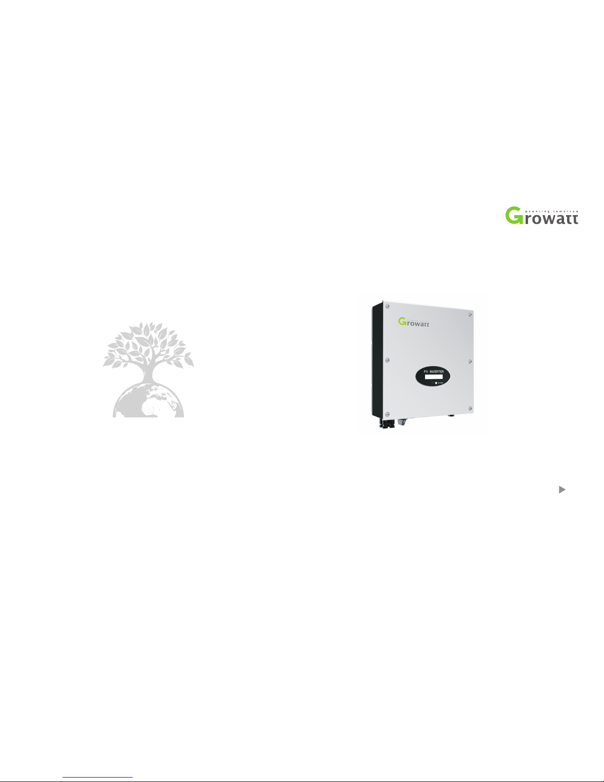
3.1 MTL-S Overview
3.2 Type label
3.3 Size and weight
3.4 Storage of Inverter
3.5 The advantage of the unit
Notes on this manual
Page 3
5.1 Safety instructions
5.2 Selecting the installation location
5.3 Mounting the Inverter
Installation
5
Electrical connection
Commissioning
Start-Up and shut
down the inverter
8.1 Start-Up the inverter
8.2 Turn-off the Inverter
6
7
8
7.1 General LCD display
7.2 Operate by knock
7.3 Communications
Maintenance and
Cleaning
9.1 Checking Heat Dissipation
9.2 Cleaning the Inverter
9.3 Checking the DC Disconnect
9
10.1 Warnings(W)
10.2 Errors(E)
Trouble shooting
10
6.1 Safety
6.2 Wiring AC Output
6.3 connecting the second protective
conductor
6.4 Connecting the PV Array (DC input)
6.5 Using shinetool to set the
information of the inverter
6.6 Grounding the inverter
6.7 Selecting country by DIP switch
6.8 Inverter demand response modes
(DRMs,only for Australia)
Contact
Manufacturer
Warranty
Decommissioning
Technical Data
PV system
installation
Compliance
Certificates
11
12
13
14
15
16
13.1 Specification
13.2 DC connector info
13.3 Torque
13.4 Accessories
15.1 List
15.2 Download Address
12.1 Dismantling the Inverter
12.2 Packing the Inverter
12.3 Storing the Inverter
12.4 Disposing of the Inverter
Page 4
1 Notes on this manual
1.1 Validity
1.2 Target Group
1.3 Additional information
This manual describes the assembly, installation, commissioning and
maintenance of the following Growatt Inverter model:
This manual is for qualified personnel. Qualified personnel have received training
and have demonstrated skills and knowledge in the construction and operation of
this device. Qualified Personnel are trained to deal with the dangers and hazards
involved in installing electric devices.
This manual does not cover any details concerning equipment connected to the
Growatt MTL-S( e.g. PV modules). Information concerning the connected
equipment is available from the manufacturer of the equipment.
2
Fi nd fu rther i nformation o n sp ecial t opics i n the d ownload a rea a t
www.ginverter.com
The manual and other documents must be stored in a convenient place and be
available at all times. We assume no liability for any damage caused by failure to
observe these instructions. For possible changes in this manual, GROWATT NEW
ENERGY TECHNOLOGY CO.,LTD accepts no responsibilities to inform the users.
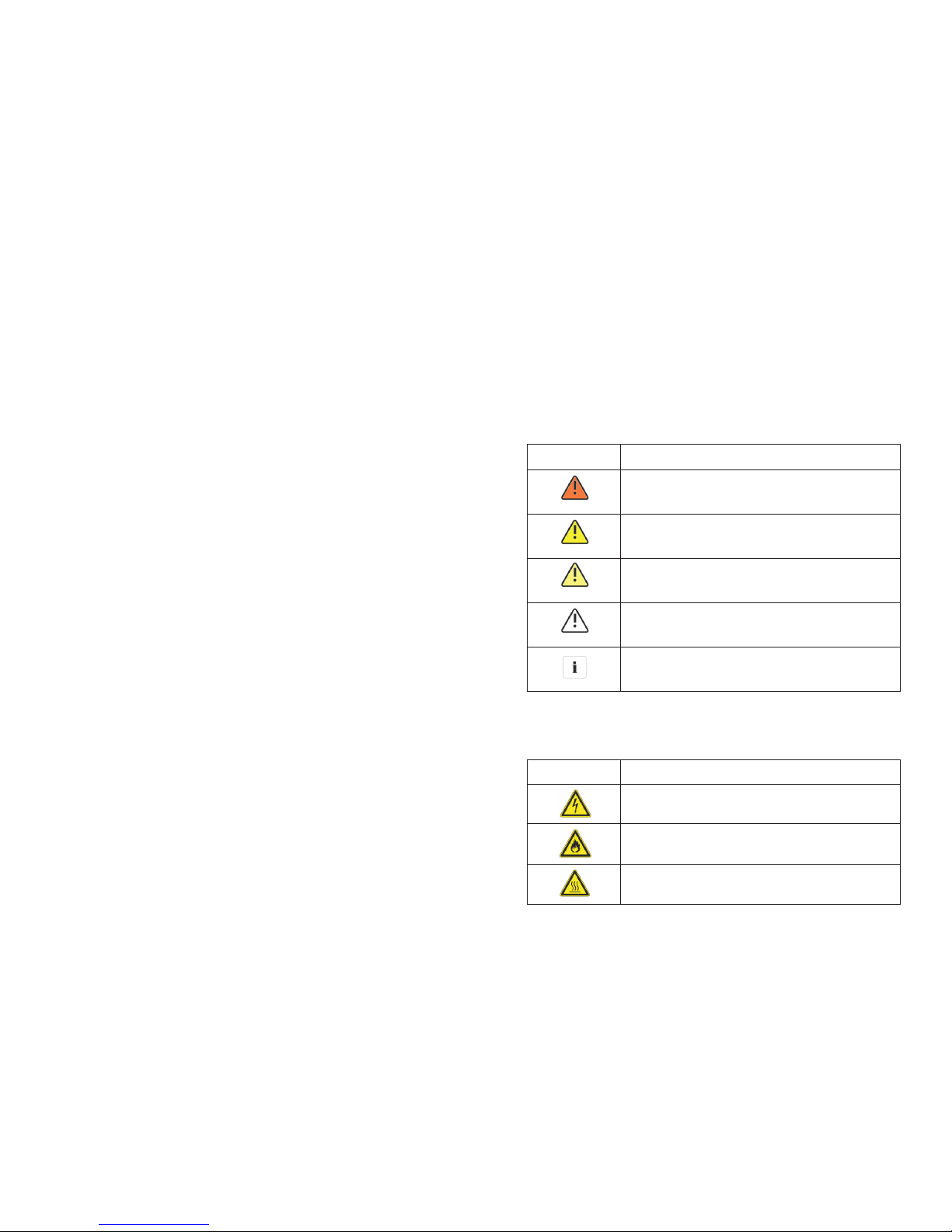
1.4.1 Warnings in this document
A warning describes a hazard to equipment or personnel. It calls attention to a
procedure or practice, which, if not correctly performed or adhered to, could result
in damage to or destruction of part or all of the Growatt equipment and/or other
equipment connected to the Growatt equipment or personal injury.
Symboldescription
DANGER
DANGER indicates a hazardous situation which, if not
avoided, will result in death or serious injury.
WARNING
WARNING indicates a hazardous situation which, if
not avoided, could result in death or serious injury.
CAUTION
CAUTION indicates a hazardous situation which, if not
avoided, could result in minor or moderate injury.
NOTICE
NOTICE is used to address practices not related to
personal injury.
Information
Information that you must read and know to ensure
optimal operation of the system.
1.4.2 Markings on this product
SymbolExplanation
Electrical voltage!
Risk of fire or explosion!
Risk of burns
1.4 Symbols in this document
1
Growatt 2500MTL-S
Growatt 3000MTL-
Growatt 3600MTL-
Growatt 4200MTL-
Growatt 5000MTL-
Growatt 5500MTL-
S
S
S
S
S
Page 5
3
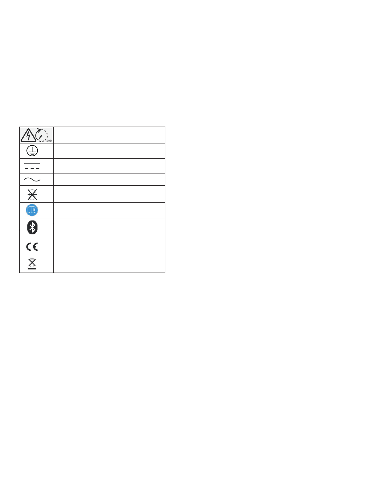
Operation after 5 minutes
Point of connection for grounding protection
Direct Current (DC)
Alternating Current (AC)
The inverter has no transformer.
Read the manual
Bluetooth communication is enabled.
CE mark.
The inverter complies with the requirements of
the applicable EC guidelines.
The inverter must not be disposed of with
the household waste.
1.5 Glossary
4
Abbreviation for "Alternating Current”
Abbreviation for "Direct Current”
Energy is measured in Wh (watt hours), kWh (kilowatt hours) or MWh (megawatt
hours). The energy is the power calculated over time. If, for example, your inverter
operates at a constant power of 4600 W for half an hour and then at a constant
AC
DC
Energy
power of 2300 W for another half an hour, it has fed 3450Wh of energy into the
power distribution grid within that hour.
Power is measured in W (watts), kW (kilowatts) or MW (megawatts). Power is an
instantaneous value. It displays the power your inverter is currently feeding into
the power distribution grid.
Power rate is the radio of current power feeding into the power distribution grid
and the maximum power of the inverter that can feed into the power distribution
grid.
Power Factor
Power factor is the ratio of true power or watts to apparent power or volt amps.
They are identical only when current and voltage are in phase than the power
factor is 1.0. The power in an ac circuit is very seldom equal to the direct product of
the volts and amperes. In order to find the power of a single phase ac circuit the
product of volts and amperes must be multiplied by the power factor.
Abbreviation for photovoltaic
The external wireless communication technology is a radio technology that allows
the inverter and other communication products to communicate with each other.
The external wireless communication does not require line of sight between the
devices and it is selective purchasing.
Power
Power rate
PV
wireless communication
Page 6
5
6
2.1 Intended Use
The unit converts the DC current generated by the photovoltaic (PV) modules to
grid-compliant alternating current and performs single-phase feed-in into the
electricity grid. Growatt 2500MTL-S,Growatt 3000MTL-,Growatt 3600MTL-
,Growatt 4200MTL-,Growatt 5000MTL-,Growatt 5500MTL-, inverters are
built according to all required safety rules. Nevertheless, improper use may cause
lethal hazards for the operator or third parties, or may result in damage to the units
and other property.
S
SSSS
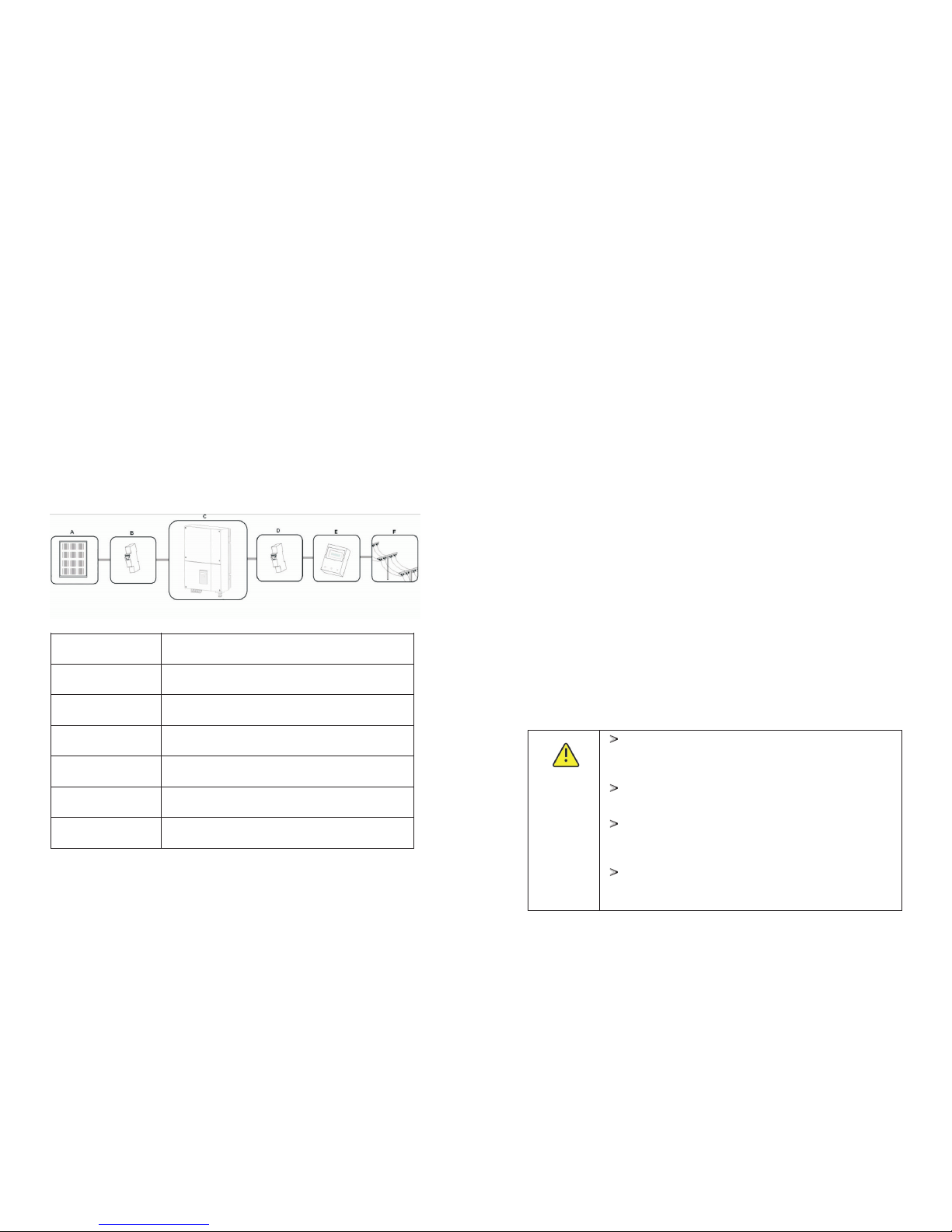
Principle of a PV plant with this GROWATT XXXXMTL- single-phase inverterS
PositionDescription
A
PV modules
B
C
D
E
F
DC load circuit breaker
Growatt Inverter
AC load circuit breaker
Energy meter
Utility grid
The inverter may only be operated with a permanent connection to the public
power grid. The inverter is not intended for mobile use. Any other or additional use
is not considered the intended use. The manufacturer/supplier is not liable for
damage caused by such unintended use. Damage caused by such unintended use
is at the sole risk of the operator.
2 Safety
PV modules Capacitive Discharge Currents
PV modules with large capacities relative to earth, such as thin-film PV modules
with cells on a metallic substrate, may only be used if their coupling capacity does
not exceed 470nF. During feed-in operation, a leakage current flows from the cells
to earth, the size of which depends on the manner in which the PV modules are
installed (e.g. foil on metal roof) and on the weather (rain, snow). This "normal"
leakage current may not exceed 50mA due to the fact that the inverter would
otherwise automatically disconnect from the electricity grid as a protective
measure.
2.2 Qualification of skilled person
This grid-tied inverter system operates only when properly connected to the AC -
distribution network. Before connecting the Growatt MTL- to the power
distribution grid, contact t he local power distribution grid company. This
connection must be made only by qualified technical personnel to connect, and
only after receiving appropriate approvals, as required by the local authority
having jurisdiction.
S
2.3 Safety instruction
The GROWATT MTL- Inverters is designed and tested according to international
safet y r equir ements (IEC6 2109-1 ,VDE-AR-N 4105,CE,V DE0126 -1-1, CE10-2 1
AS4777,NBT32004-2013,EN50438);however, certain safety precautions must be
observed when installing and operating this inverter. Read and follow all
instructions, cautions and warnings in this installation manual. If questions arise,
please contact Growatt's technical services at +86 (0)755 2747 1900.
S
2.4 Assembly Warnings
Prior to installation, inspect the unit to ensure absence of
any transport or handling damage, which could affect
insulation integrity or safety clearances; failure to do so
could result in safety hazards.
Assemble the inverter per the instructions in this manual.
Use care when choosing installation location and adhere
to specified cooling requirements.
Unauthorized removal of necessary protections, improper
use, incorrect installation and operation may lead to
serious safety and shock hazards and/or equipment
damage.
In order to minimize the potential of a shock hazard due to
hazardous voltages, cover the entire solar array with dark
material prior to connecting the array to any equipment.
WARNING
Page 7
7
CAUTION
DANGER
WARNING
8
2.5 Electrical Connection Warnings
Grounding the PV modules:The Growatt MTL- is a
transformerless inverter. That is why it has no galvanic
separation. Do not ground the DC circuits of the PV
modules connected to the Growatt MTL-. Only ground the
mounting fr ame of the PV mo dules .If you con nect
grounded PV modules to the Growatt MTL-, the error
message "PV ISO Low".
Comply with the local requirements for grounding the PV
modules and the PV generator. GROWATT recommends
connecting the generator frame and other electrically
conductive s urfac es i n a mann er w hich e nsur es
continuous conduction with ground in order to have
optimal protection of the system and personnel.
S
S
S
The components in the inverter are live. Touching live
components can result in serious injury or death.
Do not open the inverter except the wire box by
qualified persons.
Electrical installation, repairs and conversions may
only be carried out by electrically qualified persons.
Do not touch damaged inverters.
Danger to life due to high voltages in the inverter
There is residual voltage in the inverter. The inverter
takes 20 minutes to discharge
Wait 20 minutes before you open the wire box.
Persons with limited physical or mental abilities may only
work with the Growatt inverter following proper instruction
and under constant supervision. Children are forbidden to
play with the Growatt inverter. Must keep the Growatt
inverter away from children.
Mak e all e le ct ri ca l conn ect io ns ( e. g. c on duc tor
termination, fuses, PE connection, etc.) in accordance with
prevailing regulations. When working with the inverter
powered on, adhere to all prevailing safety regulations to
minimize risk of accidents.
Systems with inverters typically require additional control
(e.g., switches, disconnects) or protective devices (e.g.,
fusing circuit breakers) depending upon the prevailing
safety rules.
The Growatt Inverter converts DC Current from PV generator
int o AC current. The inv erter is suitabl e for mountin g indoors
and o utdoo rs.
You can use the AC cur rent ge rnera ted as fo llows :
CAUTION
En erg y flow s i nto t he ho use g rid. The co nsumer s
con necte d, for e xampl e, household devices or lighting,
con sume the energy. The energy left over is fed into the
pub lic grid. Wh en the Growatt is not gernerating a ny
ene rgy, e.g., at night, the c onsum ers which are c onnec ted
are supplied by th e public grid. The Growatt does not have
its own energy meter. When energy is fed into the publ ic
gri d, the en ergy me ter spi ns back wards
Ene rgy is fed directly into the public grid. The Growatt is
connec ted to a sep arate en ergy met er. T he ene rgy
pro duced is compensated at a rate depending on the
ele ctric p ower co mpany.
2.6 Operation Warnings
All operatio ns regardin g transport , installat ion and st art-u p,
inc ludin g maintenance mus t be o perat ed by qualified , trained
per sonne l and in c ompli ance with all prev ailin g cod es and
reg ulati ons.
Any time th e inverter has been d iscon necte d from the power
net work, u se extr eme caution as some comp onent s can ret ain
cha rge sufficient to create a shock hazar d; to minim ize occur rence
of such conditions, comply with all cor respo nding safe ty symbols
and m arkin gs pres ent on th e unit an d in this m anual .
In special cases, there may still be inte rfere nce for the specified
app licat ion area despite maintaining stand ardiz ed emission limit
val ues (e.g. when sensitive equipment is located at the s etup
loc ation or when the setup location is near radio or televisi on
rec eiver s).In this c ase, the ope rator is obliged to take prop er
act ion to re ctify t he situ ation .
Do no t stay cl oser th an 20 cm to t he inve rter fo r any len gth of ti me.
House
grid:
Public
grid:
WARNING
CAUTION
Ens ure al l covers and doors are closed and secure during
ope ratio n.
Alt hough de signe d t o m eet all safety requirements , s ome part s
and surfaces of Inve rter are still hot duri ng operation. To reduce
the risk of injury, do not touch the heat sink at the back of the PV-
Inv erter o r nearb y surfa ces whi le Inve rter is o perat ing.
Inc orrec t sizing of the PV plant may result in voltages being
pre sent which could destroy the inver ter. The inverte r display will
rea d the err or mess age “PV- Voltag e High! ”
Tur n the rot ary swit ch of the DC Disco nnect to the Off position
imm ediat ely.
Con tact in stall er.
Page 8
3 Product description
10
9
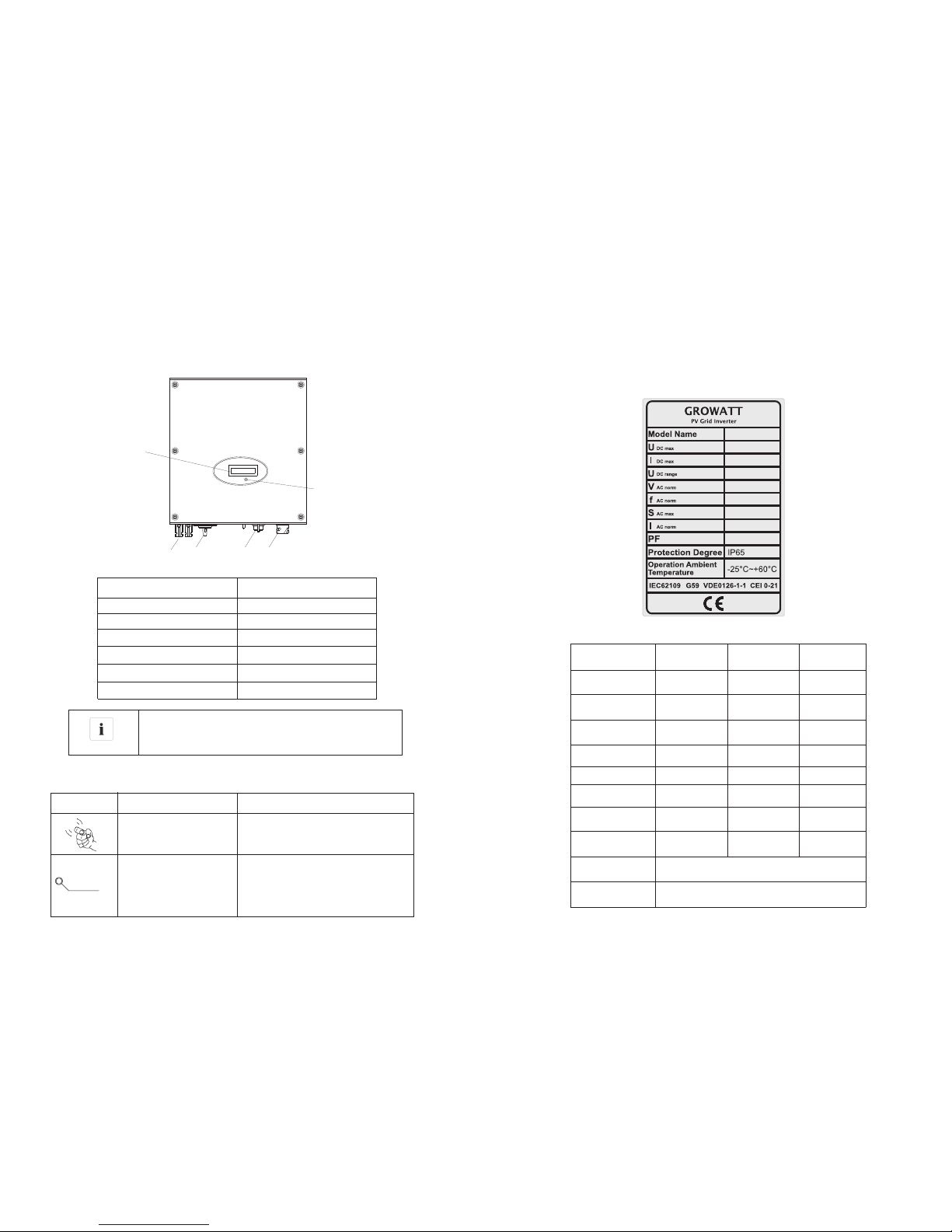
3.1 MTL-S Overview
Position
A
B
C
D
Description
LCD
LED
PV input
AC Output
Symbol on the inverter
Position
DescriptionExplanation
Tap sym bol
Set ting th e displ ay oper ation b y tappi ng
the L CD (see S ectio n 7).
NORMALL
FAULT
Inv erter s tatus s ymbol Ind icate s inver ter ope ratio n statu s
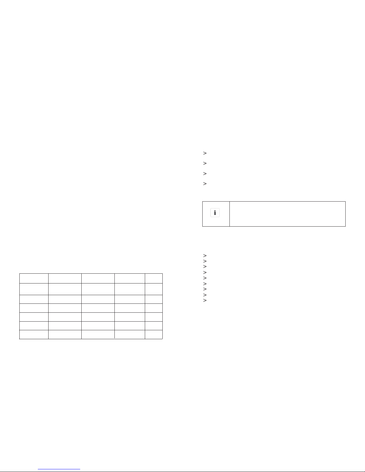
3.2 Type label
More details about the type label as the chart below:
The type labels provide a unique identification of the inverter (The type of product,
Device-specific characteristics, Certificates and approvals). The type labels are
on the right-hand side of the enclosure.
IP 65
E
DC Switch
The DC switch of Growatt MTL-S series is optional for
different countries.
Information
Gro watt
250 0MTL- S
500 V
10A /10A
70V~5 00V
230 V
50H Z
250 0VA
10. 8A
0.8 leadi ng-
0.9 5lagi ng
Gro watt
300 0MTL- S
500 V
10A /10A
70V~5 00V
230 V
50H Z
300 0VA
13A
0.8 leadi ng-
0.9 5lagi ng
Gro watt
360 0MTL- S
550 V
10A /10A
70V~5 50V
230 V
50H Z
360 0VA
15. 6A
0.8 leadi ng-
0.9 5lagi ng
Mod el Name
Max i nput DC
vol tage
Max i nput DC
cur rent
PV vo ltage
ran ge
AC no minal
vol tage
AC gr id freq uency
Max . appar ent
pow er
AC no rmal ou tput
cur rent
Pow er fact or
Env ironm ental
Pro tecti on Rati ng
Ope ratio n Ambien t
tem perat ure
-25 ...+6 0 (-1 3...+ 1 40°F
wit h derat ing abo ve 45°C 113°F
°C)
()
xxx xxxx
xxx V
xxx A/xxx A
xxx V- xxxV
xxx V
xxH z
xxx xVA
xxA
xxx
A
B
C
DE
F
F
Rj45 Port
Page 9
After long term storage, the Real Time Clock of the inverter
maybe not correct ,it will cause the energy produced today
(E_today)error ,you need to set the time and date, refer to
clause 7.2.5 setting date and time .
Information
3.3 Size and weight
Dimensions and weight
Model
Height (H)Width (W)Depth (D)
Weight
Gro watt 25 00
MTL -S
Gro watt 30 00
MTL -S
Gro watt 36 00
MTL -S
Gro watt 42 00
MTL -S
Gro watt 50 00
MTL -S
Gro watt 55 00
MTL -S
419mm 16.5inch
419mm 16.5inch
419mm 16.5inch
419mm 16.5inch
419mm 16.5inch
419mm 16.5inch
355mm 14inch
355mm 14inch
355mm 14inch
355mm 14inch
355mm 14inch
355mm 14inch
138mm 5.4inch
138mm 5.4inch
138mm 5.4inch
138mm 5.4inch
158mm 6.2inch
158mm 6.2inch
14kg
14
14kg
14kg
kg
14.5kg
14.5kg
3.4 Storage of Inverter
If you want to storage the inverter in your warehouse, you should choose an
appropriate location to store the inverter.
The unit must be stored in original package and desiccant must be left in the
package.
The storage temperature should be always between -25℃and +60℃. And the
storage relative humidity can achieve to 100%.
If there are a batch of inverters need to be stored, the maximum layers for
original carton is four.
After long term storage, local installer or service department of GROWATT
should perform a comprehensive test before installation
3.5 The advantage of the unit
Maximum efficiency of 97.5%
Wide input voltage range from 70--550Vdc
Reactive power regulate
Integrated DC switch
Multi MPP controller
DSP controller
Sound control
Multi communication pattern
Easy installation
11
12
IP 65
-25 ...+6 0 (-1 3...+ 1 40°F
wit h derat ing abo ve 45°C 113°F
°C)
()
Gro watt
420 0MTL- S
550 V
15A /15A
70V~5 50V
230 V
50H z/60H z
420 0VA
18. 5A
0.8 leadi ng-
0.9 5lagi ng
Gro watt
500 0MTL- S
550 V
15A /15A
70V~5 50V
230 V
50H z/60H z
460 0VA
20A
0.8 leadi ng-
0.9 5lagi ng
Gro watt
550 0MTL- S
550 V
15A /15A
70V~5 50V
230 V
50H z/60H z
500 0VA
21. 8A
0.8 leadi ng-
0.9 5lagi ng
Mod el Name
Max i nput DC
vol tage
Max i nput DC
cur rent
PV vo ltage
ran ge
AC no minal
vol tage
AC gr id freq uency
Max . appar ent
pow er
AC no rmal ou tput
cur rent
Pow er fact or
Env ironm ental
Pro tecti on Rati ng
Ope ratio n Ambien t
tem perat ure
Page 10

14
13
4 Unpacking and inspection
The inverter is thoroughly tested and inspected strictly before delivery. Our
inverters leave our factory in proper electrical and mechanical condition. Special
packaging ensures safe and careful transportation. However, transport damage
may still occur. The shipping company is responsible in such cases. Thoroughly
inspect the inverter upon delivery. Immediately notify the responsible shipping
company if you discover any damage to the packaging which indicates that the
inverter may have been damaged or if you discover any visible damage to the
inverter. We will be glad to assist you, if required. When transporting the inverter,
the original or equivalent packaging should be used, and the maximum layers for
original carton is four, as this ensures safe transport.
After opening the package, please check the contents of the box. It should contain
the following, Please check all of the accessories carefully in the carton. If
anything missing, contact your dealer at once.
5Installation
5.1 Safety instructions
Danger to life due to fire or explosion
Risk of burns due to hot enclosure parts
Mount the inverter in such a way that it cannot be touched
inadvertently.
5.2 Selecting the installation location
·
potential damages to device and operators.
· The installation location must be suitable for the inverter's weight and
dimensions for a long period time.
· Select the installation location so that the status display can be easily viewed.
· Do not install the inverter on structures constructed of flammable or
thermolabile materials.
·Never install the inverter in environment of little or no air flow, nor dust
environment. That may derate the efficiency of the cooling fan of the inverter.
·The Ingress Protection rate is IP65 which means the inverter can be installed
outdoors and indoors.
·The humidity of the installation location should be 100% without condensation.
·The installation location must be freely and safely to get at all times.
· Vertically installation and make sure the connection of inverter must be
downwards. Never install horizontal and avoids forward and sideways tilt.
This is guidance for installer to choose a suitable installation location, to avoid
ItemName
Number
A
B
C
D
E
Inv erter
Mou nting f rame
Saf ety-l ock scr ews
Mou nting s crews
Mou nting f rame sc rews sl eeve
1
1
4
6
6
F
Cab le glan d for AC con necti on
1
G
Use r manua l
1
I
Exp losio n bolts
4
H
Inv erter
1
J
Pap er boar d
1
F
Cab le glan d for AC con necti on
1
G
Use r manua l
1
ItemName
Number
Type2:
Type1:
H
I
J
A
B
D
E
C
F
G
Despite careful construction, electrical devices can
cause fires.
Do not install the inverter on easily flammable materials
and where flammable materials are stored.
Page 11

15
16
·
· Don't put any things on the inverter. Do not cover the inverter.
· Do not install the inverter near television antenna or any other antennas and
antenna cables.
· Inverter requires adequate cooling space. Providing better ventilation for the
inverter to ensure the heat escape adequately. The ambient temperature should
be below 40°C to ensure optimum operation.
· Do not expose the inverter to direct sunlight, as this can cause excessive
heating and thus power reduction.
· Observe the Min. clearances to walls, other inverters, or objects as shown in
the diagram:
Be sure that the inverter is out of the children's reach.
Direction
above
below
sides
front
Min. clearance (cm)
30
50
30
30
Ambient dimensions of one inverter
Ambient dimensions of a series inverters
Min.30cm
Min.50cm
Min.30cm
Min.30cm
Min.30cm
Min.30cm
Min.50cm
Min.50cm
Min.50cm
Min.50cm
Min.50cm
Min.50cm
Min.50c
m
Min.50cm
Min.50cm
Min.50cm
Min.30cm
Min.30cm
Min.30cm
Min.30cm
Page 12

17
18
Please make sure the inverter is installed at the right place。The inverter
can't install close to trunk。
·
that the cooling air of the adjacent inverter is not taken in.
·If necessary, increase the clearance spaces and make sure there is enough
fresh air supply to ensure sufficient cooling of the inverters.
·The inverter can't install to solarization,drench,firn location. We suggest that
the inverters should be installed at the location with some cover or protection.。
There must be sufficient clearance between the individual inverters to ensure
5.3 Mounting the Inverter
5.3.1 Mounting the Inverter with bracket
Using the mounting frame as a template, drill 4 holes as illustrated in image.
DANGER
In order to avoid electrical shock or other injury, inspect
existing electronic or plumbing installations before drilling
holes.
Fix the mounting frame as the figure shows. Do not make the screws to be flush
to the wall. Instead, leave 2 to 4mm exposed.
There are two types of installation mode,please choose the
corresponding installation instructions.
NOTICE
Type1:
Page 13

1920
Mark four points at the wall via the hole of the paper board ,then remove the paper
board .or mounting frame
Knock explosion bolt into the Ø8 holes, screw the nuts to fix the bolt.
Type2:
5.3.2 Fixed the inverter on the wall
Falling equipment can cause serious or even fatal injury,
never mount the inverter on the bracket unless you are
sure that the mounting frame is really firmly mounted on
the wall after carefully checking.
WARNING
Rise up the inverter a little higher than the bracket. Considered the weight of
them.During the process please maintain the balance of the inverter.
Hang the inverter on the bracket through the match hooks on bracket.
After confirming the inverter is fixed reliably, fasten four M6 safety-lock sokets
head cap screws on the left and right side firmly to prevent the inverter from
being lifted off the bracket.
Hang MTL-S onto the explosion bolt,then screw the four nuts with spanner to
fix MTL-S tightly.
Type1:
Type2:
Page 14

22
21
6 Electrical Connection
6.1 Safety
6.2 Wiring AC Output
When using inverter with VDE-AR-N 4105, because the
inverter's displacement factor adjust function had to accorded
to VDE-AR-N 4105,the PV-inverter system total capacity cannot
be over 13.8KVA.
When using inverter with CEI 0-21: if the inverter system total
capacity more than3KW and up to 6KW,the displacement factor
is adjustable between 0.95leading to 0.95 lagging ,and not need
the external SPI.if the inverter system total capacity more than
6KW,,the displacement factor is adjustable between 0.9leading
to 0.9 lagging ,and need the external SPI。
!
NOT ICE
Danger to life due to lethal voltages!
High voltages which may cause electric shocks are present
in the conductive parts of the inverter. Prior to performing
any work on the inverter, disconnect the inverter on the AC
and DC sides
WARNING
Danger of damage to electronic components due to
electrostatic discharge.
Take appropriate ESD precautions when replacing and
installing the inverter.
WARNING
You must install a separate single-phase circuit-breaker or other
load disconnection unit for each inverter in order to ensure that
the inverter can be safely disconnected under load.
NOTE:The inverter is equipped with integrated RCM(Residual
current operated monitor)a nd RCD(Residual current and
protective device) which are used for preventing from being
electric shock. An external built RCD in fact is not necessary .
If the network operator stipulate an external built RCD,you must
choose a residual-current protective device that triggers in the
event of residual current more than 300mA.
Position
Description
A
B
C
D
E
F
PV modules
DC load circuit breaker
Growatt Inverter
AC load circuit breaker
Energy meter
Utility grid
You must install a se parate sing le-pha se circuit- breake r or ot her load
disconnection unit for each inverter in order to ensure that the inverter can be
safely disconnected under load.
We suggest you choice the AC breaker rating current in this table:
we recommend electrical connection as follows
The AC wiring step:
1. The grid connection is made using 3 conductors (L, N, and PE).
Growatt 2500MTL-S
Growatt 3000MTL-S
Growatt 3600MTL-S
Growatt 4200MTL-S
Growatt 5000MTL-S
Growatt 5500MTL-S
18A/230V
20A/230V
24A/230V
28A/230V
30A/230V
32A/230V
Page 15

2423
2. Remove the parts of the AC connection plug from the accessory bag.Guide the
pressure screw, sealing ring, threaded sleeve over the AC cable.
Max. cable length
33m
42m
28m
36m
Wire suggestion length:
If the installation requires,the ground terminal can be used to connect a second
protective conductor or as a equipotential bonding.the second protective poing
local as figure below.
3. Insert the stripped and bared conductors L,N,PE into the screw terminals with
sign L,N,PE on the socket element and tighten the screws firmly.
Conductor cross
section
5.2 m m² 10AWG
6.6 m m² 9AWG
6.3 connecting the second protective conductor
Gro watt
360 0MTL- S
Gro watt
420 0MTL- S
Gro watt
300 0MTL- S
40m
50m
Max. cable length
26m
33m
Conductor cross
section
5.2 m m² 10AWG
6.6 m m² 9AWG
Gro watt
500 0MTL- S
Gro watt
550 0MTL- S
24m
30m
Gro watt
250 0MTL- S
48m
60m
4.Push the threaded sleeve into the socket element; screw the pressure screw
tightly onto the threaded sleeve;
5.Finally, insert the AC connection plug into the AC connection receptacle on the
inverter.
socket elementthreaded sleeve
stealing ring
pressure screw
Lock the housingUnlock the housing
Page 16

25
26
The Growatt MTL-S single-phase inverter has 2 independent input : input A &
input B.
6.4 Connecting the PV Array (DC input)
6.4.1 Conditions for DC Connection
The diagram drawing of DC side is shown as below, notice that the connectors are
in paired (male and female connectors). The connectors for PV arrays and
inverters are H4 connectors;
Suggestions for the PV modules of the connected strings:
·Same type
·Same quantity of PV modules connected in series
String A
String input
Input1
String input
String B
A
B
Input2
Growatt MLT-10
MPPT
1
MPPT
2
If the inverter is not equipped with a DC switch but this is
mandatory in the country of installation, install an external DC
switch.
The following limit values at the DC input of the inverter must not
be exceeded:
Types
Max current
input A
Max current
input B
10A
10A
10A
15A
15A
15A
10A
10A
10A
15A
15A
15A
Gro watt 25 00MTL -S
Gro watt 30 00MTL -
Gro watt 36 00MTL -
Gro watt 42 00MTL -
Gro watt 50 00MTL -
Gro watt 55 00MTL -
S
S
S
S
S
CAUTION
s
Page 17

27
28
6.4.2 Connecting the PV Array (DC input)
DANGER
Danger to life due to lethal voltages!
Before connecting the PV array, ensure that the DC switch
and AC breaker are disconnect from the inverter. NEVER
connect or disconnect the DC connectors under load.
Make sure the maximum open circuit voltage (Voc) of each
PV string is less than 550Vdc.
Check the design of the PV plant. The Max. open circuit
voltage, which can occur at solar panels temperature of -
10℃ , must not exceed the Max. input voltage of the
inverter.
Improper operation during the wiring process can cause
fatal injury to operator or unrecoverable damage to the
inverter. Only qualified personnel can perform the wiring
work.
WARNING
6.5 Using shinetool to set the information of the inverter
About the software of shinetool and the usage of it please download from the web:
www.ginverter.com/Download.aspx
6.6 Grounding the inverter
The inverter must be connected to the AC grounding conductor of the power
distribution grid via the ground terminal (PE)
6.7 Selecting country by DIP switch
6.7.1 Location of the DIP switch
The DIP switch is located on the left of the RS232 interface at the bottom of the
inverter, as the figure below.
Because of the transformerless design, the DC positive
pole and DC negative pole of PV arrays are not permitted to
be grounded.
WARNING
1. DC Connector 2. RS232 Interface 3. AC Connector
NOTE: Before selecting country, please turn off DC input and AC grid, then
unscrew the dam-board of the DIP switch by appropriate tool.
The internal structure of the DIP switch is as the following figure:
1
2
3
DIP Swich
2
1
3
4
5
Page 18

30
29
Whe n the cab les of AC si de and DC s ide are a ll well c onnec ted, be fore co mmiss ionin g, the
cou ntry sa fety st andar d must be s elect ed by the D IP switch.
The D IP switch is com posed o f five- digit b inary n umber P INS. Th e differen t combi natio n of the
fiv e PINS ca n repre sent di fferent inve rter' s model , which i s corre spond ing to th e local g rid
sta ndard . Each sm all whi te PIN ha s two sta tuses , when se t upwar d to 'ON' , its val ue turn s to
'1' , when se t downw ard, it s value t urns to '0'. Co ncern ing the m atchi ng of the P IN stat us and
the c ountr y safet y stand ard, pl ease re fer to th e attac hed tab le.
Do not disconnect the DC connectors under load.
Improper operation during the wiring process can cause
fatal injury to operator or unrecoverable damage to the
inverter. Only qualified personnel can perform the wiring
work.
Commissioning
7
7.1 General LCD display
7.1.1 Power on display
Requirements:
The AC cable is correctly connected.
The DC cable is correctly connected.
The country is set incorrectly(See accessory.)
When inverter powered on, LCD background will light automatically. Starting-up
display sequence, once the PV power is sufficient, inverter displays information as
shown in the flow chart as follow:
Mod ule: xx xxxx
Ser No: xxx xxxxx xx
FW Ver sion: x .x.x
Con nect in : xxS
Con nect : OK
xxx x.xVA xxxx.x W
7.1.2 LCD Display when background light off
After power on information displayed, there will be another 4 interfaces displayed
in turn, if there is no knock signal input.
DANGER
WARNING
6.7.2 DIP switch option corresponding to the country
Whe n setting the DIP, you must turn off the AC breake r and DC
bre aker.
Aft er s ettin g the DIP, pleas e powe r on the inverte r and chec k the
model dis play. If th e la st charact er of the mo del nam e is
cor respo nding to the count ry safet y sta ndard as th e abo ve table, it
mea ns your s ettin g is succ essfu l.
You should chan ge the t ime displ ayed on the LCD of i nvert er to yo ur
loc al time a fter in verte r start s up.
DAN GER
!
NOT ICE
If t he country i s set inco rrect ly, please shut d own the in verte r and set
aga in.
6.8 Inverter demand response modes (DRMs,only for Australia)
This series inverter has the function of demand response modes,moreover, We
use RJ45 socket as inverter DRED connection.
6.8.1 RJ45 socket pin assignment
Ass ignme nt for in verte rscap able of
bot h charg ing and d ischa rging
PIN
1
DRM 5
2
DRM 6
3
DRM 7
4
DRM 8
5
Ref Gen
6
COM /DRM0
7
/
8
/
6.8.2 Method of asserting demand response modes
MOD E
Rj4 5 socke t
Ass erted b y short ing pin s
Req uirem ent
DRM 0
DRM 5
DRM 6
DRM 7
DRM 8
5
6
Ope rate th e disconn ectio n device
Do no t gener ate pow er
Do no t gener ate at mo re than 5 0% of rat ed powe r
Do no t gener ate at mo re than 7 5% of rat ed powe r
AND S ink rea ctive p ower if c apabi e
Inc rease p ower ge nerat ion (su bject t o const raint s
fro m other a ctive D RMs)
1
5
2
5
3
5
4
5
1
→
8
Pin As signm ents Fr ont View
RJ45 Socket
123 45678
RJ45 Plug
Page 19

32
31
Programming
Program State
The First Line Of LCD
STATEDISPLAY CONTENT
Wait State
Standby
Waiting
Connect in xxS
Reconnect in xxS
Connect OK
xxxx.xVA xxxx.x W
Error: xxx
Auto Testing
Inverter State
Fault State
Auto Test State
Update Software
REMARK
PV voltage low
Initial waiting
System checking
System checking
Connect to Grid
Inverter watt at working
System Fault
Protection auto test
7.1.3 The Second line can change by knock on
CYCLE DISPLAY
DISPLAY TIME/S
REMARK
2
2
The inverter model
The software version
Position
Detail
AInverter operation message
B
Inverter state information
2
4
The Serial Number
The energy today
Page 20

34
33
4
The energy all
4
PV input watt
4
The PV and Bus Votage
4
The grid system
4
4
Enable auto test
Setting status
Communications Address
of the inverter
4
CYCLE DISPLAY
DISPLAY TIME/S
REMARK
4
The last 5dated failure reports
4
year/month/day/time of
the inverter
7.1.4 Connecting messages
When inverter started to connect to grid, the following message will appear on
LCD screen.
Connect to gird interface
7.2 Operate by knock
7.2.1 Knock type and definition
The inverter can support three kinds of knock: single knock, double knock and
thrice knock. Each kind of knock has different function. Refer to specified
definition in Table below:
Knock type
Single knock
Double knock
Thrice knock
Definition
KeyDown
KeySET
KeyEnter&ESC
7.2.2 Light background and check running information
Before light the background, the three types of knock functions are the same: just
light the background.
Note:That the background light will automatically off if there is no knock detected
in 180seconds.
Setting...
4
Set Zigbee Channal
Zigbee no conn
Page 21

3536
According to the LCD display,you need to input three numbers: 123.You should
finish several steps as below:
1.When the LCD stays bright, single knock to ‘Setting…’,and then double knock to
enter ‘INPUT 123:xxx’interface.
2. Double knock to make the first number flash, single knock to change the
number, and the first number you need to input is ‘1’. Double knock to enter the
second number while the first number was ‘1’.
3. When the second number is flashing ,single knock to change the number,and
the second number you need to input is ‘2’. Double knock to enter the last number
while the first number was ‘2’.
4. When LCD displays ‘INPUT 123:123’, triple knock to enter the setting interface.
5. Single knock to ‘COM Address: xxx’, and then double knock to enter the setting
status, single knock to change the COM Address. When setting finishes, wait for
30s or triple knock to save your setting.
7.2.4 Set inverter display language
1. If you want to set inverter display language, repeat the steps as described in
section 7.2.3.
2. When LCD displays ‘INPUT 123:123’, triple knock to enter the setting interface.
3. Single knock to select the language you want, when setting finishes, wait for 30s
or triple knock to save your setting.
7.2.3 Set inverter’s COM address
When communicating with monitoring software or device, the software or device
may regard inverter ’s COM address as communication address (Also may use
inverter’s serial number as communication address).
Before entering the ‘COM Address: xxx’ setting interface,you need to enter a
password as below:
COM Address: 01
Set Language
The inverter provides seven languages: English, German, Spanish, Italian ,
French,Hungarian and Turkish. The number on Set language interface is
sequence number of these five languages, the sequence number and its
corresponding language are showing in Table below:
Language
Sequence Number
Italian
English
German
Spanish
French
0
1
2
3
4
7.2.5 Set inverter time
1. If you want to set inverter time, repeat the steps as described in section 7.2.3.
2. When LCD displays ‘INPUT 123:123’, triple knock to enter the setting interface.
3. Single knock until LCD displaying ‘xxxx/xx/xx xx:xx’, and then double knock to
enter the setting status, the numbers begin to flash. Single knock to change the
number, each knock makes the flashing number add ‘1’, and double knock to
shift to next number setting. When setting finishes, wait for 30s or triple knock
to save your setting.
7.2.6 Inverter faulty messages
When system faulty or inverter error occurred, inverter will display faulty message
or error code on its LCD screen.
INPUT 123:XXX
Hungarian
5
Turkish
6
2015/09/03 15:11
4505.5VA 4485.5W
4505.5VA 4485.5W
4505.5VA 4485.5W
4505.5VA 4485.5W
4505.5VA 4485.5W
Setting…
Page 22

3837
7.3 Communications
7.3.1 RS232 (standard)
RS 232 could be chosen for ShineNet ,WiFi Module.
7.3.2 External WiFi (Optional)
WIFI module (it is available from Growatt) can be used as an optional monitoring
schome.More details refer to the WIFI module manual.
7.2.8 Auto test (only for Italy)
Knock to make the display bright→ knock to“Enable Auto test”→ double knock to
enter “Waiting to start”→knock to start auto test and wait for the test result.
7.2.9 Communication Type choice
If you select RS232 or External wireless, you must set the 2-PIN switch to different
status. The 2-PIN switch is located beside the RS232 interface, as the figure
below.
1. When ‘RS232’ is selected, you have to set PIN1 of the switch downward to OFF.
2. When ‘Exter wireless’ is selected, you have to set PIN1 of the switch upward to
ON.
7.2.7 AC Error Record Checking
When the LCD stays bright, single knock to ’AC Error Record’, and then double
knock to enter the checking status. Single knock to check each error item, triple
knock can exit.
1. If the inverter connects with PV panel arrays and the input voltage is higher
than 100Vdc, while the AC grid is not connected yet, LCD will display messages in
order as below:
Growatt Inverter”-> “NO AC CONNECTION”. The display repeats “NO AC
CONNECTION” and the LED will be red.
2. Turn on the AC breaker or close the fuse between inverter and grid, the system
will operate normally.
3. Under normal operating conditions, the LCD displays ‘xxxx.xVA xxxx.x W’ at
State info, this is the power fed into grid. LED turns green.
4. Finish commissioning.
2
1
Page 23

39
40
8.1 Start-Up the inverter
1. Connect the AC breaker of the inverter.
2. Turn on the dc switch, and the inverter will start automatically when the input
voltage is higher than 90V.
8.2 Turn-off the Inverter
Do not disconnect the DC connectors under load.
Turn –off the inverter step:
1.Disconect the line circuit breaker from single-phases grid and prevent it from
being reactivated.
2. Turn off the dc switch.
3. Check the inverter operating status.
4. Waiting until LED, display have go out, the inverter is shut down.
DANGER
8 Start-Up and shut down the inverter
Maintenance and Cleaning 9
If the inverter regularly reduces its output power due to high temperature, please
improve the heat dissipation condition. Maybe you need to clean the heat sink.
9.1 Checking Heat Dissipation
9.2 Cleaning the Inverter
If the inverter is dirty, turn-off the AC breaker and DC switch ,waiting the inverter
shut down ,then clean the enclosure lid, the display, and the LEDs using only a wet
cloth. Do not use any cleaning agents (e.g. solvents or abrasives).
9.3 Checking the DC Disconnect
Check for externally visible damage and discoloration of the DC Disconnect and
the cables at regular intervals.If there is any visible damage to the DC Disconnect,
or visible discoloration or damage to the cables, contact the installer.
Once a year, turn the rotary switch of the DC Disconnect from the On position to
the Off position 5 times in succession. This cleans the contacts of the rotary switch
and prolongs the electrical endurance of the DC Disconnect.
Page 24

42
41
10 Trouble shooting
Sometimes, the PV inverter does not work normally, we recommend the following
solutions for common troubleshooting. The following table can help the technician
to understand the problem and take action.
10.1 Warnings(W)
Warnings(W) identify the current status of the Growatt MTL-S. Warnings do not
relate to a fault. When a (W) with a number after it appears in the display, it
indicates a Warning Code and is usually cleared through an orderly shutdown/re-
set or a self corrective action performed by the inverter. See the (W) codes in the
Err or mess age
Des cript ion
Sug gesti on
No AC
Con necti on
AC V
Out range
No ut ility g rid
con necte d or util ity
gri d power f ailur e
1.C heck AC wi ring.
2.C ontac t Growa tt.
Uti lity gr id volt age
is ou t of perm issib le
ran ge.
1.C heck gr id volt age.
2.I f the err or mess age sti ll exis ts desp ite the g rid
vol tage be ing wit hin the t olera ble ran ge, con tact
Gro watt.
AC F
Out range
Uti lity gr id
fre quenc y out of
per missi ble ran ge.
1.C heck gr id freq uency.
2.I f the err or mess age is di splay ed desp ite the
gri d frequ ency be ing wit hin the t olera ble ran ge,
con tact Gr owatt .
Ove r
Tempe ratur e
Tempe ratur e
out range
1.ch eck the i nvert er oper ation s tate
2.I f the err or mess age is di splay ed stil l,ple ase
con tact Gr owatt .
PV Is olati on
Low
Ins ulati on prob lem
1.C heck if p anel en closu re grou nd prop erly.
2.C heck if i nvert er grou nd prop erly.
3.C heck if t he DC bre aker ge ts wet.
4.I f the err or mess age is di splay ed desp ite the
abo ve chec king pa ssed, c ontac t Growa tt.
Out put Hig h
DCI
Out put cur rent DC
offset too high
1.R estar t inver ter.
2.I f error m essag e still e xists ,cont act Gro watt.
Res idual I
Hig h
Lea kage cu rrent
too h igh
1.R estar t inver ter.
2.I f error m essag e still e xists , conta ct Grow att.
PV Vol tage
Hig h
The D C input v oltag e
is ex ceedi ng the
max imum to lerab le
val ue.
Dis conne ct the DC s witch i mmedi ately.
Aut o Test
Fai led
Aut o test di dn't
pas sed.
Con tact po wer com pany,By t hey dec ide whe ther
to ma nuall y cance l.
10.2 Errors(E)
Errors(E) codes identify a possible equipment failure, fault or incorrect inverter
setting or configuration. Any and all attempts to correct or clear a fault must be
performed by qualified personnel. Typically, the (E) code can be cleared once the
cause or fault is removed. Some of the (E) codes, Error as indicated in the table
below, may indicate a fatal error and require you to contact the supplier or the
Growatt to replace a new one.
Err or code
Des cript ion
Sug gesti on
Err or: 101
Com munic ation f ault Sl ave
pro cesso r can't r eceiv e data
fro m Maste r proce ssor.
1.R estar t inver ter
2.I f error m essag e still e xists , conta ct Grow att.
Err or: 102
Con siste nt faul t. Data r eceiv ed
by Ma ster an d Slave p roces sor
are d ifferent. Th e reaso n can be
uti lity gr id volt age or fr equen cy
cha nge fre quent ly.
1.R estar t inver ter.
2.I f error m essag e appea rs freq uentl y or erro r
mes sage st ill exi sts aft er repl aceme nt, che ck
uti lity gr id. f you r equir e help, c ontac t Growa tt.
3.I f error m essag e still e xists , conta ct Grow att.
Err or: 116
EEP ROM fau lt
Con tact Gr owatt .
Err or: 117
Err or: 118
Err or: 119
Err or: 120
Err or: 121
Err or: 122
Rel ay faul t
Con tact Gr owatt .
Con tact Gr owatt .
Con tact Gr owatt .
Ini t model f ault
GFC I Devic e Damag e
HCT fault
Com munic ation f ault.
Mas ter pro cesso r can't
rec eive da ta from S lave
pro cesso r.
Bus v oltag e fault
Con tact Gr owatt .
1.R estar t the inv erter
2.I f error m essag e still e xists , conta ct
Gro watt.
Con tact Gr owatt .
Note:The latest 5 NS(Network and System) protection records can be read by
LCD or communication software. An interruption of ≤3 Sec to the power supply
does not lead to any loss of fault records (according to VDE-AR-N 4105, cl.6.5.1).
Err or: 111
PE ab norma l
1.C heck PE ,to ens ure tha t the PE li ne cont act
goo d.
2.C heck th e L and the N line t o ensur e that th ey
are n ot reve rsed.
3.R estar t inver ter.
4.I f error m essag e still e xisit s,con tact Gr owatt .
Page 25

4344
11 Manufacturer Warranty
Please refer to the warranty card.
Decommissioning 12
12.1 Dismantling the Inverter
1.Disconnect the inverter as described in section 8.
2.Remove all connection cables from the inverter.
Danger of burn injuries due to hot enclosure parts!
Wait 20 minutes before disassembling until the housing
has cooled down.
3. Screw off all projecting cable glands.
4. Lift the inverter off the bracket and unscrew the bracket screws.
CAUTION
12.2 Packing the Inverter
If possible, always pack the inverter in its original carton and secure it with
tension belts. If it is no longer available, you can also use an equivalent carton.
The box must be capable of being closed completely and made to support both
the weight and the size of the inverter.
12.3 Storing the Inverter
Store the inverter in a dry place where ambient temperatures are always
between -25°C and +60°C.
12.4 Disposing of the Inverter
Do not dispose of faulty inverters or accessories together with
household waste.Please accordance with the disposal regulations
Page 26

45
46
13 Technical Data
13.1 Specification
Input data
Spe cific ation s
Model
Max . recom mende d
PV po wer(f or modu le STC)
Max . DC volt age
Sta rt volt age
PV vo ltage r ange
MPP voltag e range /
nom inal vo ltage
Num ber of in depen dent
MPP inputs / s tring s per
MPP input
Max . input c urren t
of tr acker A/tra ckerB
Output (AC)
Nom inal AC
out put pow er
Max . AC appar ent
pow er
AC no minal v oltag e;
ran ge
AC gr id freq uency ;
ran ge
Pha se fact or at
rat e power
Dis place ment po wer
fac tor, con figur able*
THD I
AC co nnect ion
Max . outpu t
cur rent
Gro watt
300 0MTL- S
350 0W
500 V
100 V
70V- 500V
80V- 500V
/36 0V
2/1
10A /10A
300 0W
300 0VA
220 V/230 V/240 V; 180Vac-280 Vac
50, 60H;±5 H zz
1
0.8 leadi ng…
0.9 5lagg ing
<3%
Sin gle pha se
13. 6A
Gro watt
360 0MTL- S
410 0W
550 V
100 V
70V- 550V
80V- 550V
/36 0V
2/1
10A /10A
360 0W
360 0VA
50, 60H;±5 H zz
1
0.8 leadi ng…
0.9 5lagg ing
<3%
Sin gle pha se
16. 3A
Gro watt
250 0MTL- S
290 0W
500 V
100 V
70V- 500V
80V- 500V
/36 0V
2/1
10A /10A
250 0W
250 0VA
50, 60H;±5 H zz
1
0.8 leadi ng…
0.9 5lagg ing
<3%
Sin gle pha se
11.3A
Efficiency
Max . efficiency
97. 4%97. 5%
Eur o - weigh ted
efficien cy
97%97%
MPP T efficien y
99. 5%
99. 5%
97. 4%
97%
99. 5%
Ful l load dc v oltag e range
160 V-450V19 0V-500 V130 V-450V
Max . input c urren t per
str ing of tr acker A/ track er B
10A /10A10A /10A10A /10A
Protection
devices
DC re verse p olari ty
pro tecti on
yes ye s
DC sw itch ra tiing
for e ach MPP T
yes ye s
Out put Ove r curre nt
pro tecti on
yes ye s
Out put Ove rvolt age
Pro tecti on-va risto r
yes ye s
Gro und fau lt
mon itori ng
yes ye s
Gri d monit oring
yes ye s
Int egrat ed all - po le
sen sitiv e leaka ge
cur rent mo nitor ing uni t
yes ye s
General Data
Dim ensio ns (W / H / D)
Weight
Ope ratin g tempe ratur e
ran ge
Noi se emis sion (t ypica l)
355 /419/ 138mm
14K G
-25 ...+6 0℃ 13...+ 14 0°F)
wit h derat ing abo ve 45°C(113°F)
(-
≤ 25 dB (A)
yes
yes
yes
yes
yes
yes
yes
355 /419/ 138mm
14K G
≤ 25 dB (A)
Alt itude
Up to 2 000m(65 60ft) wi thout p ower de ratin g
Rel ative h umidi ty
Sel f-Con sumpt ion nig ht
Topol ogy
Coo ling co ncept
Env ironm ental
Pro tecti on Rati ng
100 %
< 0.5 W
tra nsfor merle ss
Nat ural
IP 65
100 %
< 0.5 W
tra nsfor merle ss
Nat ural
IP 65
Features
DC co nnect ion:
H4/ MC4(o pt)
AC co nnect ion
Con necto r
Dis play
LCD
Int erfac es: Rs2 32
/ RF/ Wi-Fi /Ethe rnet
yes /opt/
opt /opt
Warran ty:
5 yea rs / 10 yea rs
yes / opt
Cer tific ates an d
app roval s
H4/ MC4(o pt)
Con necto r
LCD
yes /opt/
opt /opt
yes / opt
H4/ MC4(o pt)
Con necto r
LCD
yes /opt/
opt /opt
yes / opt
Gro watt
300 0MTL- S
Gro watt
360 0MTL- S
Gro watt
250 0MTL- S
355 /419/ 138mm
14K G
≤ 25 dB (A)
100 %
< 0.5 W
tra nsfor merle ss
Nat ural
IP 65
CE, IEC62 109,V DE012 6-1-1 ,G83, G59,A S4777 ,VDE- AR-N- 4105,
NBT 32004 -2013 ,EN50 438,C EI-02 1,INM ETRO
Page 27

48
47
Input data
Spe cific ation s
Model
Max . recom mende d
PV po wer(f or modu le STC)
Max . DC volt age
Sta rt volt age
PV vo ltage r ange
MPP voltag e range /
nom inal vo ltage
Num ber of in depen dent
MPP inputs / s tring s per
MPP input
Max . input c urren t
of tr acker A/tra ckerB
Output (AC)
Nom inal AC ou tput po wer
Max . AC appar ent pow er
AC no minal v oltag e;
ran ge
AC gr id freq uency ;
ran ge
Pha se fact or at rat e
pow er
Dis place ment po wer fac tor,
con figur able*
THD I
AC co nnect ion
Max . outpu t curre nt
220 V/230 V/240 V;
180 Vac- 280Vac
Gro watt
500 0MTL- S
530 0W
550 V
100 V
70V- 550V
80V- 550V/ 360V
2/1
15A /15A
460 0W
460 0VA
50, 60H;±5 H zz
1
0.8 leadi ng…
0.9 5lagg ing
<3%
Sin gle pha se
20. 9A
Gro watt
550 0MTL- S
575 0W
550 V
100 V
70V- 550V
80V- 550V /3 60V
2/1
15A /15A
500 0W
500 0VA
50, 60H;±5 H zz
1
0.8 leadi ng…
0.9 5lagg ing
<3%
Sin gle pha se
22. 7A
Efficiency
Max . efficiency
97. 5%
Eur o - weigh ted
efficien cy
97%
MPP T efficien y
99. 5%
97. 5%
97%
99. 5%
220 V/230 V/240 V;
180 Vac- 280Vac
Ful l load dc v oltag e range
160 V-500V175 V-500V
Max . input c urren t per
str ing of tr acker A/ track er B
15A /15A15A /15A
Gro watt
420 0MTL- S
480 0W
550 V
100 V
70V- 550V
80V- 550V/ 360V
2/1
15A /15A
420 0W
420 0VA
50, 60H;±5 H zz
1
0.8 leadi ng…
0.9 5lagg ing
<3%
Sin gle pha se
19A
97. 5%
97%
99. 5%
150 V-500V
15A /15A
220 V/230 V/240 V;
180 Vac- 280Vac
Protection
devices
DC re verse p olari ty
pro tecti on
yes yes
DC sw itch ra tiing
for e ach MPP T
yes yes
Out put Ove r curre nt
pro tecti on
yes yes
Out put Ove rvolt age
Pro tecti on-va risto r
yes yes
Gro und fau lt moni torin g
yes yes
Gri d monit oring
yes yes
Int egrat ed all - po le
sen sitiv e leaka ge
cur rent mo nitor ing uni t
yes yes
General Data
Dim ensio ns (W / H / D)
Weight
Ope ratin g tempe ratur e
ran ge
Noi se emis sion (t ypica l)
-25 ...+6 0℃ 13...+ 14 0°F)
wit h derat ing abo ve 45°C(113°F)
(-
≤ 25 dB (A)≤ 25 dB(A )
Alt itude
Up to 2 000m(65 60ft) wi thout p ower de ratin g
Rel ative h umidi ty
Sel f-Con sumpt ion nig ht
Topol ogy
Coo ling co ncept
Env ironm ental
Pro tecti on Rati ng
100 %
< 0.5 W
tra nsfor merle ss
Nat ural
IP 65
100 %
< 0.5 W
tra nsfor merle ss
Nat ural
IP 65
Features
DC co nnect ion:
AC co nnect ion
Dis play
Int erfac es: Rs2 32/
RF/ Wi-Fi /Ethe rnet
Warran ty: 5 yea rs / 10 yea rs
Cer tific ates an d
app roval s
CE, IEC62 109,V DE012 6-1-1 ,G83, G59,A S4777 ,VDE- AR-N- 4105,
NBT 32004 -2013 ,EN50 438,C EI-02 1,INM ETRO
H4/ MC4(o pt)
Con necto r
LCD
yes /opt/
opt /opt
yes / opt
H4/ MC4(o pt)
Con necto r
LCD
yes /opt/
opt /opt
yes / opt
Gro watt
500 0MTL- S
Gro watt
550 0MTL- S
355 /419/ 158mm
14. 5KG
355 /419/ 158mm
14. 5KG
0.9 5lead ing…0 .95la gging w ith VDE -AR-N 4 105
0.9 5lead ing…0 .95la gging w ith CEI 0 -21 (Sy stem po wer les s than 6K W)
0.9 leadi ng…0. 9lagg ing wit h CEI 0-2 1 (Syst em powe r large r than 6K W)
*
14K G
≤ 25 dB (A)
355 /419/ 138mm
< 0.5 W
tra nsfor merle ss
Nat ural
IP 65
100 %
H4/ MC4(o pt)
Gro watt
420 0MTL- S
yes
yes
yes
yes
yes
yes
yes
Con necto r
LCD
yes /opt/
opt /opt
yes / opt
Page 28

13.4 Accessories
In the following table you will find the optional accessories for your product. If
required, you can order these from GROWATT NEW ENERGY TECHNOLOGY
CO.,LTD or your dealer.
13.2 DC connector info
DC connector info H4/MC4(opt)
13.3 Torque
Enclosure lid screws
Shell and RS232 screws
AC terminal
M6 soket head cap screws for securing
the enclosure at the bracket
Additional ground screws
7kg.cm
7kg.cm
6kg.cm
20kg.cm
20kg.cm
4950
Shipped to a Growatt service centre for repair, or repaired on-site, or exchanged
for a replacement device of equivalent value according to model and age.
The warranty shall not cover transportation costs in connection with the return of
defective modules. The cost of the installation or reinstallation of the modules
shall also be expressly excluded as are all other related logistical and process
costs incurred by all parties in relation to this warranty claim.
14PV system installation
(B) multi inverter
Installation with multiple inverters on a single phase system
(A) Single inverter
Name Brief description
External WiFi
Page 29

5251
15.1 List
15 Compliance Certificates
Certified countries
With the appropriate settings, the unit will comply with the requirements specified
in the following standards and directives .
GROWATT can preset special grid parameters for other countries installation
locations according to customer requests after evaluation by GROWATT.
You can make later modifications yourself by changing software parameters with
respective communication products (e.g. shinebus or shineNet ect). To change the
grid-relevant parameters, you need a personal access code, if you need it ,please
contact with GROWATT.
15.2 Download Address
www.ginverter.com
Contact 16
If you have technical problems about our products, contact the
GROWATT Serviceline. We need the following information in
order to provide you with the necessary assistance:
Inverter type
Serial number of the inverter
Event number or display message of the inverter
Type and number of PV modules connected
Optional equipment
GROWATT NEW ENERGY TECHNOLOGY Co.,LTD
Bui lding B , Jiayu I ndust rial Pa rk, #28 , Guang Hui Roa d,
Shi yan Str eet, Ba oan Dis trict , Shenz hen, P.R.China
T 0755-295 15888
F 075 5-274 72131
E ser vice@ ginve rter.c om
W www. ginve rter.c om
VDE 0126- 1-1
VDE -AR-N 4105
CEI 0 -21
CE
G59
G83
As4 777
IEC -6210 9
NBT 32004 -2013
EN 50 438
Page 30

53
Annex:
Auto test (only for Italy):
Knock to make the display bright→ knock to“Enable Auto test”→ double knock to
enter “Waiting to start”→the inverter will start auto test and wait for the test
result.When the inverter start auto test,the LCD will display below message:
 Loading...