

Growatt 4200 MTL, Growatt 5000 MTL, Growatt 3600 MTL Installation & Operation Manual
GROWATT NEW ENERGY CO., LTD
No.12 Building, Xicheng Industrial
Zone, Bao’an District, Shenzhen, P. R.China
+ 86 755 2747 1900
+ 86 755 2749 1460
service@ginverter.com
www.ginverter.com
T
F
E
W
Installation
&
Operation Manual
Growat t 3600 MTL
Growat t 4200 MTL
Growat t 5000 MTL
GR - UM - 002 - 02

Notes on this manual
1.1 Valid ity
1.2 Targ et Gro up
1.3 Safe ty
Growatt MTL Inverter
2.1 Over view
Unpacking and inspection
Installation
4.1 Safe ty ins truc tions
4.2 Sele ctin g the IN STALL ATION l ocation
4.3 Fixe d the mo unti ng on the wal l
4.4 Fixe d the in vert er on the wal l
4.5 Chec k Ivew rter i nstalla tion S tatu s
Electrical Connection
5.1 Syst em Dia gram w ith Inver ter
Electr ical c onne ction
5.2 Safe ty
5.3 Conn ecti ng to th e grid (AC ut ilit y)
5.4 Conn ect to P V Pane l (DC input )
5.5 Coun try Se lect ing
Directory
1
2
3
4
5
2.2 Iden tify ing mo del and bas ic dat ashe et
5.6 Comm issi onin g
The Growatt is a P V I nverter tha t c onve rts DC Current from PV gene rato r into AC
current . The Growatt is su itab le for m ounting i ndoo rs and o utdoors .
Notes on this manual 1
1.1 Validity
1.2 Target Group
1.3 Safety
You ca n use th e AC cur rent g ern erat ed as fo llows:
Approp ria te Usage
This man ual d escr ibes the as semb ly, ins tallati on, co mmi ssio ning and ma inte nance of
the foll owin g Growatt I nverter s:
Growat t 3600 MTL
Growat t 4200 MTL
Growat t 5000 MTL
This man ual is f or qua lified pe rson nel. Q ualifie d pers onne l have recei ved train ing
and have d emon stra ted skill s and kn owle dge in the co nstr ucti on and oper atio n of
this dev ice. Q uali fied pers onne l are tr aine d to dea l with the da nger s and ha zard s
involv ed in in stal ling elec tric d evic es.
Contact
Display
6.1 LCD di spla y
6.2 LCD co ntrol
6.3 Sett ing th e LCD di splay
Modes of Operation
7.1 Norm al mod e
7.2 Faul t mode
7.3 Shut down m ode
Inverter Status
Communitions
9.1 Comm unic atio ns softwa re
instru ctio ns
9.2 Moni tor
Trouble Shooting
System Fault
Inverter Failure
Specifications
Growatt Factory
warranty
Warranty conditions
6
7
8
9
10
11
12
13
14
15
16
This manu al doe s not cov er any detai ls concern ing eq uipm ent co nnec ted to th e
Gro watt MTL ( e. g. PV module s). Info rmat ion conc ern ing the conn ecte d eq uipment
is avail able f rom th e manu fact urer o f the equip ment .
Additi onal i nfor mation
Find furt her in form ation on spe cial topic s in th e down load a rea at ww w.gin vert er.co m
1
Growatt MTL Inverter 2
2.1 Overview
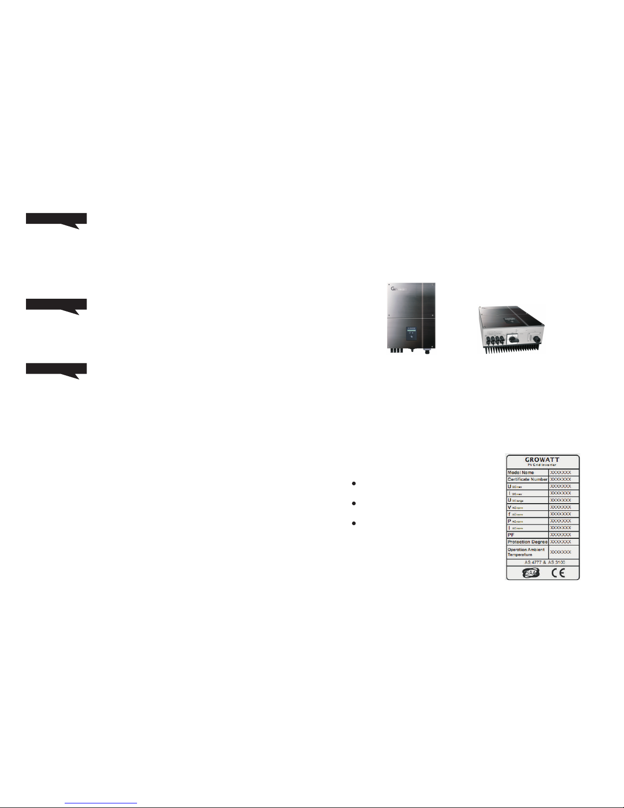
2.2 Identifying model and basic datasheet
You ca n iden tify t he pv inver ter by t he typ e label. It i s on the l eft si de of the enc losu re.
The type o f product (Typ e/Mo del) .
Device -spe cifi c charact eris tics .
Certif icat es and a ppro vals .
House gr id:
Energy f lows into the h ouse grid . The c onsu mers conn ect ed, for exa mple, hou sehold
device s or ligh ting, c onsu me the energy. T he ener gy left over is f ed into the public
grid. W hen t he Gr owat t is not g ernerat ing a ny energ y, e .g., at ni ght, the cons umers
which are c onnecte d are su ppli ed by th e public gr id.
The Growa tt does not h ave it s own en ergy mete r. When energ y is fed i nto th e public
grid, th e ener gy met er spins ba ckwa rds.
Public g rid
Energy is fed dire ctly int o t he publ ic grid. The Growa tt is connect ed to a s epar ate
energy me ter. The energy prod uced i s comp ensa ted at a rate depend ing on th e
electr ic pow er com pany.
Stand- alon e grid :
The Gro watt is co nnected to a stand-al one grid . Th e energy generat ed is con sumed
directl y on site, su rplu s ener gy can be sto red in b atte ries .
DC and AC Switch
Separa te th e Grow att s ecurely f rom t he gr id an d the PV genera tors usin g DC a nd AC
Switch . You m ust prov ide an A C circuit bre aker. If G rowa tt D C Switch is i nclu ded in
the deli very o f the Gr owat t, it mu st be used fo r oper atin g the inver ter.
Grounding the PV modules
The Grow att 3600 MTL, 4200 MTL a nd 5000M TL is a tra nsfo rmerles s inv erte r. Tha t is
why it has n o ga lvan ic s epar ation. D o no t gro und the DC ci rcui ts o f th e PV modu les
connec ted to t he Gro watt . Only g roun d the mount ing fr ame of t he PV modul es.
If you con nect g roun ded mo dule s to the Growatt, t he err or mes sage " PV ISO Low" .
Info
of the loc al uti lity c ompany be fore
: Polici es var y from o ne uti lity c ompany to a noth er. Con sult w ith a re pres enta tive
Based on tr ansform er les s t echn olog y,IEC 6173 0 d eman d m atching class A PV
module . we norm ally reco mmen d M onoc ryst alline sili con and poly crys tall ine silicon
module . But it c an also b e app lied to s ome t hin-fil m tec hnology whi ch cl aims
workab le wit h tran sformer l ess in vert er.
2 3
INSTALLATION 4
4.1 Safety instructions
A
B
C
D
E
F
G
Do not rem ove the cas ing. I nverter con tains no user ser viceabl e
parts. Refer servi cing t o qual ifie d serv ice perso nnel . All wi ring
and ele ctri cal install atio n should be c onducte d by a qualif ied
servic e pers onnel and must m eet natio nal requi reme nts of AS47 77
or VDE01 26-1 -1.
Both AC and DC volta ge sou rces are termi nate d ins ide th e PV
Invert er. Plea se discon nect t hese c ircuits b efor e serv icing.
When a phot ovoltai c pa nel is e xpos ed to l ight, i t gener ates a DC
voltag e. Wh en co nnec ted t o thi s equipm ent, a pho tovo ltai c panel
will cha rge th e DC lin k capacit ors.
Energy s tore d in thi s equ ipme nt’s DC l ink c apac itor s present s a risk
of e lect ric s hock. Even after the unit is d isco nnected from the grid
and p hoto voltaic pan els, h igh vol tage s may still exis t insi de the
PV- Inve rter. Do not re move t he cas ing until a t leas t 5 minu tes after
discon nect ing al l power sou rces .
This unit is d esigned to fe ed power to th e pub lic p ower gri d
(utili ty) o nly. Do not conn ect t his u nit t o an A C sou rce o r
genera tor. C onne ctin g In vert er t o extern al de vic es co uld resu lt i n
seriou s dama ge to yo ur equipm ent.
Carefu lly r emove th e unit fr om i ts pa ckaging and ins pect for
extern al damage. If y ou fin d any imp erfecti ons, pleas e cont act
your loc al dea ler.
Althou gh desi gned to me et all saf ety requir emen ts, som e parts
and su rfac es of I nver ter are stil l h ot d urin g o pera tion . To redu ce
the risk of in jury, do no t touch the heat sink at th e bac k of t he PVInvert er or ne arby s urfaces w hile I nver ter is oper atin g.
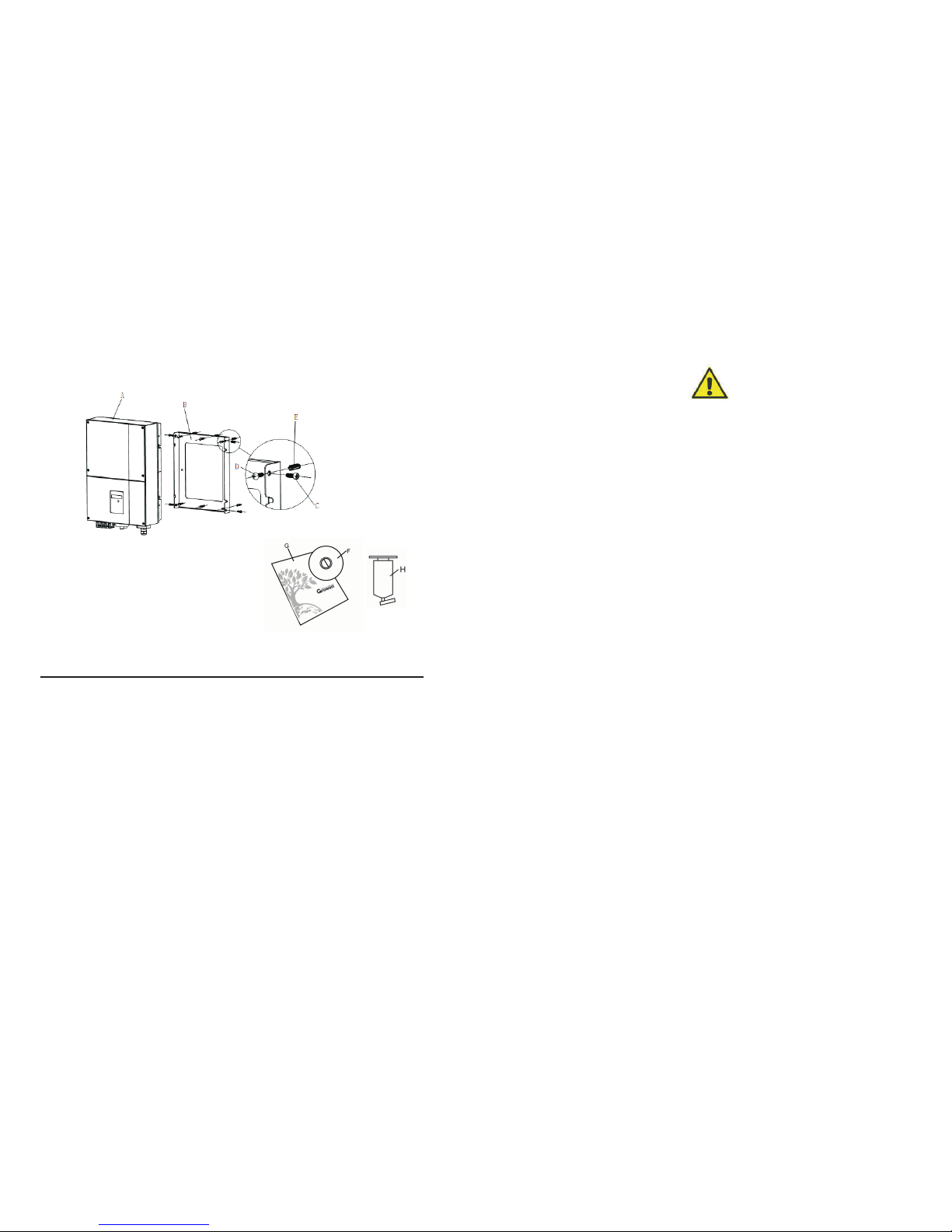
Item
A
B
C
D
E
F
G
H
Name
solar in vert er
Mounti ng fra me
Safety -loc k scre ws
Mounti ng scr ews
Mounti ng fra me scr ews sleev e
Monito r soft ware (disk)
manual
Blueto oth
Quanti ty
1
1
2
4
4
1(Opti onal )
1
1(Opti onal )
3 Unpacking and inspection
After open ing t he packa ge, p leas e check t he co nten ts of the box.
It sho uld c onta in the fo llow ing:
4 5
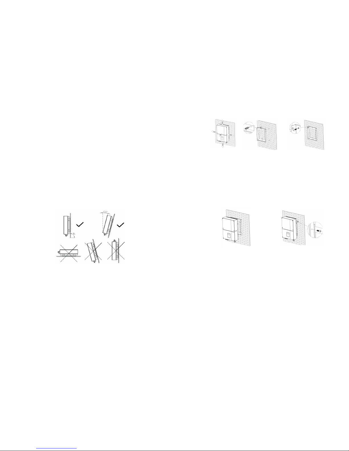
4.3 Fixed the mounting on the wall
Invert er requires adeq uate c ooli ng space. A llow a t leas t 20cm spac e
above an d belo w the in verte.
Using th e moun ting f rame as a tem plat e, dri ll 4 holes as i llus trat ed in
image.
Fix the mo unti ng fra me as the fig ure shows. D o not ma ke the s crew s to be
flush to t he wal l.In stead, le ave 2 to 4 mm exp osed
A
A
B
B
C
4.4 Fixed the inverter on the wall
Hang the i nver ter on t he mounti ng fra me.
Insert s afet y-lo ck screws to t he bottom l eg to se cure t he inv erter.
4.5 Check Inverter Installation Status
A
B
C
D
4.2 Selecting the INSTALLATION location
The in stal lati on meth od a nd moun ting loca tion mu st b e suita ble for the
weight a nd dim ensions o f the inver ter. Select a w all or soli d vert ical
surfac e that c an sup port the PV- Inve rter.
Mount on a s olid surf ace , T he mou nting loc atio n mus t be access ible a t all
times.
Vertica l inst alla tion or til ted ba ckwa rds by m ax. 15 °.
The conn ecti on are a must p oint d ownwards.
Do not ins tall h oriz ontally.
A
B
C
D
E
Check th e uppe r stra ps of PV-Inv erte r and en sure i t fits o n to the brac ket.
Check the se cure mount ing of the PV-Inve rter by tryin g to ra ise it from the
bottom .The PV- Inverte r should re main fi rmly attach ed.
Select the inst alla tion loc atio n s o t hat the sta tus display can be easi ly
viewed .
Choose a st rong moun ting wa ll to p reve nt vibr atio ns whil e in verter is
operat ing.
6
7
 Loading...