

Page 1
Installation
&
Operation Manual
GR - UM - 033 - A - 04
Growatt 750-S
Growatt 1500-S
Growatt 2000-S
Growatt 2500-S
Growatt 3000-S
Growatt 1000-S
Shenzhen Growatt New Energy Technology CO.,LTD
Bui lding B , Jiayu I ndust rial Pa rk, #28 , Guang Hui Roa d,
Shi yan Str eet, Ba oan Dis trict , Shenz hen, P.R. Chin a
T 075 5-29 51588 8
F 075 5-274 72131
E ser vice@ ginve rter.c om
W www. ginve rter.c om
Page 2

About Manual
1.1 Val idit y
1.2 Targ et Gro up
1.3 Add itio nal infor mati on
Safety
2.1 Inte nded U se
Product Description
3.1. Ove rvie w
3.2. Type la bel
3.3. Dim ensi ons an d Weig ht
3.4. Tran spor t and St ore
Unpacking
Contents
1
2
3
4
2.2 Qual ific atio n of skille d pers on
1.4 Symb ols in t his do cument
1.5 Glos sary
2.3 Safe ty ins truc tion
2.4. Asse mbly Wa rnings
2.5. Ele ctri cal Co nnectio n Warni ngs
2.6. Ope rati on Warning s
3.5. The ad van tage o f Inve rter
Page 3
Commissioning
6
Installation
5.2. Sel ecti ng mou nting loc atio n
5.4. Con nect s witc h
5.3. Mou ntin g Inve rter
5.1. Saf ety in stru ctions
5
5.5. Gro undi ng
5.6. Con nect g rid ty pe
5.7. Ele ctri cal co nnectio n
6.1. Par amet ers se tting
6.2. Ind epen dent f unction o ptio n
6.3. LCD d ispl ay
6.4. Com muni cati on
6.5. Com miss ioni ng the inve rter
6.6. Mon itor ing to ol instru ctio ns
Startup and Shutdown
the Inverter
7
7.1. Sta rt up th e Inve rter
7.2. Shu tdow n the In verter
Operation Modes
8
8.1. Wait ing mo de
8.2. Nor mal mo de
8.3. Fau lt mod e
8.4. Shu tdow n mode
9.2. Che ckin g the DC s witch
9.3. Cle anin g the In verter
9.1. Che ckin g heat d issipat ion
Maintenance and
Cleaning
9
10.1 Warn ings (W)
10.2 Err ors( E)
Trouble Shooting
10
Decommissioning
11
11.1 . Dism ant ling t he Inv erte r
11.2 . Pack ing t he Inv erte r
Technical Data
12
12.1. Sp ecif icat ion
12.2. DC c onne ctor i nfo
12.3. Torqu e
11.3 . Stor ing t he Inv erte r
11.4 . Disp osi ng of th e Inve rter
PV System Installation
13.2. Mu lti in vert ers
13.1. Si ngle i nver ter
13
14.1. Li st
14.2. Do wnlo ad add ress
Compliance Certificates
14
Contact
15
Page 4

About Manual 1
1.1 Validity.
This ins tall ation and user g uide desc ribe s the a ssembly, i nsta llat ion,
commis sion ing, comm unic atio n, ma inte nance, op erat ing a nd failur e sear ch of t he
follow ing Gr owa tt inv erte rs:
This m anu al does not cove r a ny deta ils conc erni ng equi pment c onn ecte d t o t he
Growat t ( e.g. PV m odul es) . In form ati on c oncerni ng t he conn ecte d e quip ment is
availa ble fr om the m anufact urer o f the eq uipment
1.2. Target group
This ma nual is for qua lified p erso nnel wh o hav e receiv ed tr aini ng a nd ha ve
demons trat ed sk ills and kno wle dge i n the co nstr ucti on and op erat ion of t his
device . Qual ifie d Pers onne l are traine d to deal w ith th e dang ers and haz ards
involv ed in in stal ling elec tric d evic es.
1.3. Additional information
Fi nd fu rt he r i nf or ma ti on on s pe ci al to pi cs i n th e dow nl oa d are a a t
The m anua l a nd othe r d ocum ents m ust be stored in a c onve nie nt plac e and be
availa ble a t al l ti mes. We assum e no liab ilit y fo r an y dam age caus ed b y fai lur e to
observ e thes e inst ruction s. For p ossi ble chang es in th is man ual, SHEN ZHEN
GROWATT NE W ENE RGY TE CHN OLOG Y CO.,LTD ac cept s no r espo nsi bili ties to
inform t he use rs.
www.gin vert er.co m
1
Manual Introduce and Copyright
Copyri ght © 2 010 Shen zhe n G rowatt New Ene rgy Tech nology Co., Ltd,
All righ ts re served.
No part of this d ocu ment may be r epr oduced, s tor ed in a r etrieva l sys tem,
or trans mitted, in an y form or by any mean s, electr oni c, mec han ical,
photog rap hic, magneti c or ot herwise , wit hout the prior w rit ten permi ssi on
of Shenz hen G rowatt Ne w Ene rgy Tech nol ogy Co., Lt d.
Sh en zhe n G rowat t N ew En er gy Techno lo gy Co ., Ltd m ak es no
repres ent ations, express or implied , w ith resp ect to this documen tat ion
or any of the equipment and/ or soft war e it may de scribe, inc lud ing (wi th
no lim itation ) an y impli ed w arr anties of u tility, merc han tabilit y, or fit ness
for any par tic ular pur pos e. All suc h wa rra nties ar e ex pressly dis claimed .
Neithe r Shenz hen Gr owa tt N ew E ner gy Technology Co., Lt d no r it s
distri but ors or de ale rs s hall be liable for any in dir ect, incide nta l, or
conseq uen tial dama ges u nder any ci rcu mstance s.
(Th e exclusi on of impl ied war ranties may not app ly in all cases unde r
some sta tut es, and thu s the a bove excl usi on may not ap ply.)
Specif ica tions are subject to chan ge wit hou t noti ce. Every att empt h as
been mad e to mak e this d ocu ment comp lete, acc ura te and up- to- date.
Reader s are caution ed, h owe ver, t hat G row att r ese rves the r ight to ma ke
change s wit hout n oti ce and s hal l not be respon sib le for any d ama ges,
includ ing in dir ect, i nci dental o r co nse quentia l da mages, caused by
relian ce o n th e m ate rial p res ented, i ncl uding, but n ot l imited t o,
omissi ons , typographi cal e rrors, ar ith metical e rro rs or l isting er ror s in th e
conten t mat erial.
All trade mar ks are rec ogn ized even if the se are not marked sep arately.
Missin g de signati ons do not me an t hat a p roduct o r br and is no t a
regist ere d tradema rk.
SHENZH EN GR OWATT NE W ENE RGY TE CHNOLOG Y CO.,LTD
Buildi ng B, Jia yu Indu str ial Par k, #28, Gua ngH ui Roa d, Shiy an Stre et,
Baoan Di str ict, Shen zhe n, P.R.C hin a
Growatt 750-S
Growatt 1500-S
Growatt 2000-S
Growatt 2500-S
Growatt 3000-S
Growatt 1000-S
Page 5
1.4. Symbols in this document
A warn ing desc rib es a haza rd to equi pmen t or pers onnel. It calls atte ntion to a
proced ure or prac tice, whi ch, i f not c orrectl y perform ed or a dher ed to , cou ld result
in dama ge to or dest ruct ion of p art or all of t he Grow att equi pmen t a nd/o r o ther
equipm ent co nnec ted to the Gr owat t equi pment or pe rson al inj ury.
1.4.1. Warnings in this document
Symbol description
DANGER
DA NGER in dic ate s a h azardou s s itu atio n wh ich , i f not
avoide d, wil l resu lt in death o r seri ous in jury.
WAR NING
WAR NING i ndic ates a ha zar dous si tua tion which , if no t
avoide d, cou ld res ult in deat h or ser ious i njury.
CAUTIO N
CAUTIO N in dic ates a hazard ous si tua tion w hic h, i f n ot
avoide d, cou ld res ult in mino r or mod erat e injury.
NOTICE
NOTICE is used to addr ess practice s not r elat ed to pers onal
injury.
Inform atio n
Inform atio n that yo u must read an d know to en sure op tima l
operat ion of t he sys tem.
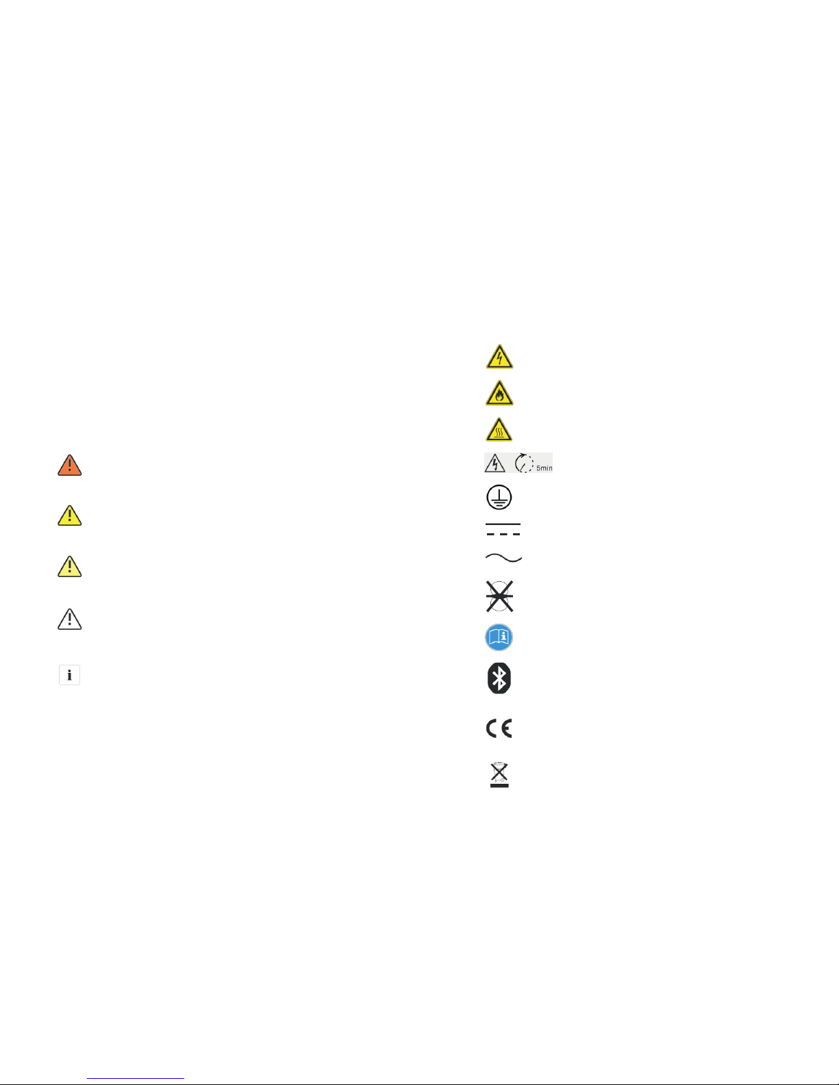
1.4.2. Markings on this product
Symbol Explanation
Electrical voltage!
Risk of fire or explosion!
Risk of burns
Operation after 5 minutes
Point of connection for
grounding protection.
Direct Current (DC)
Alternating Current (AC)
The inverter has no transformer.
Read the manual.
Bluetooth communication is enabled.
CE mark.
The inverter complies with the
requirements of the applicable
EC guidelines.
The inverter must not be disposed
of with the household waste.
32
Page 6

5
4
1.5.Glossary
AC
Abbrev iati on for " Alterna ting C urre nt"
DC
Abbrev iati on for " Direct Cu rren t"
Energy is me asu red in W h (w att hour s), kWh (ki lowa tt h ours ) or MWh (meg awa tt
hours) . The en ergy is the powe r cal cula ted over ti me. I f, for exam ple, y our i nver ter
operat es at a cons tant pow er of 150 0W for half an hour and the n a t a c onst ant
power of 1000 W fo r a noth er half an hour, it h as fed 125 0 Wh of ener gy into the
power di stri buti on grid wit hin th at hou r.
Energy
Power i s me asu red in W (watts) , kW (ki lowa tts) or MW (megaw atts ). P ower is a n
instan tane ous valu e. I t d ispl ays the powe r y our inverter is curr entl y f eedi ng into
the powe r dist ribu tion grid .
Power
Power rat e i s t he radi o o f c urre nt pow er feed ing into the powe r dist ribu tion gri d
and th e m axim um powe r of th e i nver ter that can fee d in to the power di stribut ion
Power rate
Power fac tor is t he rati o o f t rue powe r o r w atts to apparent power o r v olt amps .
They are iden tic al only wh en curr ent and vo ltag e are in pha se than th e powe r
factor i s 1.0. T he pow er in a n ac cir cuit i s ver y seld om equ al to t he dir ect pr odu ct of
the vo lts and ampe res. In orde r to find the powe r of a si ngle phas e ac circ uit the
produc t of vol ts and a mperes mu st be mu ltip lied by the p ower f acto r.
Power Factor
PV
Abbrev iati on for p hotovol taic
The exte rna l wir eles s com muni cati on te chnolog y is a r adio tech nol ogy that allow s
the in vert er and othe r co mmunica tion product s to com muni cate wit h ea ch othe r.
The ex ter nal wireless comm uni cati on does not requ ire line of sig ht betw een the
device s and it i s sele ctive pur chas ing.
wireless communication
Safety 2
2.1. Intended Use
The un it c onverts the DC curr ent generat ed b y the p hoto voltaic (PV) modu les to
grid-c ompl iant al tern atin g curren t and pe rfor ms si ngle-ph ase f eed- in i nto t he
electr icit y grid . Gro watt 7 50-3 000-S ser ies in verters a re bui lt accord ing to a ll
requir ed safe ty rules. Neve rthe less , i mpr oper use may cause leth al haza rds for
the oper ator o r thi rd par ties , or ma y resu lt in d amag e to the unit s and ot her
proper ty.
Princi ple of a P V plan t with this G rowa tt XXX X single- phas e inve rter
The inve rte r may on ly be ope rate d with a pe rman ent co nnec tion t o the pu blic
power gr id.
The inve rter is no t inte nded fo r mob ile use . A ny oth er or addi tion al use is no t
consid ered the inte nded use. The manu fact urer/su ppli er i s no t liabl e fo r da mage
caused b y suc h uni nten ded u se. D amag e cau sed by such unin tend ed us e is at the
sole ris k of the o pera tor.
PV modul es Cap acit ive Disch arge C urre nts
PV mod ules with larg e ca pacitie s re lati ve to e arth , su ch as t hin- film PV m odules
with cel ls on a met alli c sub stra te, m ay on ly be used i f the ir co upling ca pac ity does
not exce ed 47 0nF. During f eed- in op erat ion, a lea kage c urrent fl ows f rom the cel ls
to eart h, the size of whic h d epen ds on the manner in whic h t he P V m odul es are
instal led (e.g. fo il on meta l r oof) and on the weat her (rai n, snow ). T his "nor mal"
leakag e cur rent ma y not exceed 50 mA due to th e fact th at the in vert er wou ld
otherw ise au tomatic ally d isco nne ct fro m t he el ectr icit y g rid a s a p rotecti ve
measur e.
Page 7
6
7
This g rid -tie d i nver ter syst em oper ate s o nly when prop erl y conne cted to the A C
–distr ibut ion n etwo rk. B efor e con nect ing t he in vert er in vert er to t he po wer
di stri but ion g rid, contac t t he lo cal p ower di stri but ion grid co mpan y. Th is
connec tion mus t b e m ade only by qual ifie d tech nica l p ersonne l t o c onne ct, and
only aft er re cei ving app ropr iate app rov als, as r equi red b y the loc al au thor ity
having j uris dict ion.
2.2. Qualification of skilled person
The GRO WATT In vert ers are de sign ed and te sted ac cord ing to i nternat iona l
safety req uire ment s; h owev er, c erta ins afet y pr ecau tion s mu st b e ob serv ed w hen
instal ling and o per atin g this in vert er. Read and fo llow al l inst ruct ions , caution s
and wa rnin gs in th is ins tall ation m anual. If qu esti ons ar ise , pl ease co ntac t
Growat t's te chni cal servi ces at + 86 (0) 755 2951 58 88.
2.3. Safety instruction
2.4. Assembly Warnings
Symbol description
WAR NING
Prior to inst all atio n, in spec t the unit to ensure a bse nce o f any
transp ort or hand ling dam age, wh ich coul d affe ct insulat ion
integr ity or s afety c lear ance s; f ail ure to d o so coul d r esul t in
safety h azar ds.
Assemb le the inve rter per the ins truc tio ns in t his manua l. Use
care wh en c hoos ing in stal lati on l ocat ion an d adhere to
specif ied co olin g require ment s.
Unauth oriz ed r emoval of nec ess ary pro tect ion s, i mpro per
use, i ncor rect in stal lati on and ope rati on m ay lead to seri ous
safety a nd sho ck haz ards and/ or equ ipme nt damage .
In ord er to mini mize th e p otentia l o f a shoc k h aza rd due to
hazard ous v olta ge, cov er th e ent ire sol ar ar ray w ith dar k
materi al pri or to co nnectin g the ar ray to a ny equipm ent.
Ground ing t he PV mo dul es: Th e G row att i nver ter is a
transf orme rles s i nver ter. Th at i s w hy i t h as n o g alva nic
separa tion . D o not grou nd the DC circ uits of the PV modu les
connec ted to t he inv erte r. O nly grou nd the moun ting fra me of
the P V modu les. If you con nect gro unded PV modules to the
Growat t inve rter s, the erro r mess age "P V ISO Low".
Comply w ith th e l oca l r equi reme nts f or gro undi ng th e P V
mo dule s a nd th e P V gener ato r. GROWATT r eco mmends
co nne cti ng t he g ene rat or f ram e a nd o ther e lectr ica lly
conduc tive sur face s in a m anne r whi ch en sure s con tinu ous
co ndu ctio n wi th gr ound th ese i n o rde r to have o ptim al
protec tion o f the sy stem and pe rson nel.
CAUTIO N
2.5. Electrical Connection Warnings
Symbol description
DANGER
Th e c omp one nts in the in ver ter ar e l ive . Tou ching li ve
compon ents c an res ult in seri ous in jury o r death.
Do not open the inv erte r exce pt the wire box by qual ifie d
person s.
E lectric al ins tallati on, re pairs and c onversi ons ma y onl y be
carrie d out by e lect rically q uali fied p ersons.
Do not tou ch dam aged i nverter s.
Danger t o life d ue to hi gh voltag es in th e inve rter
Ther e is r esi dual volt age i n the inv erte r. The inve rter takes
20 minut es to di scha rge.
Wai t 20 min utes b efore you o pen th e wire b ox.
Person s wi th l imit ed p hysi cal or m enta l ab ili ties may o nly work
with th e Gro watt inve rter fol lowi ng pr oper instruc tion and u nder
consta nt supe rvis ion . Chil dre n are forbid den to pla y with th e
Growat t inve rter. Must k eep t he Growat t inve rte r away fro m
childr en.
Page 8
8
9
WAR NING
CAUTIO N
Make al l el ectr ica l connec tion s (e .g. con duct or t ermi nation,
fuses, PE co nnec tion, et c.) in ac cord ance wi th p reva ilin g
regula tion s. Whe n wor king w ith th e inverte r powe red on , adh ere
to all pre vail ing sa fety regu lati ons to m inimize r isk of a ccid ents.
System s wit h inv erte rs typic ally requ ire a ddi tion al co ntro l (e.g.,
switch es,d isco nnects) or pr otec tiv e dev ices (e.g., f usin g circui t
breake rs) de pend ing upon th e prev aili ng safety r ules .
The G rowa tt Inve rter co nver ts DC Curr ent fro m PV gen erat or
into AC curr ent. Th e i nverter is sui tabl e f or moun ting ind oors
and outd oors .
You ca n use th e AC c urre nt gen erat ed as f ollo ws:
Energy flows i nto th e ho use gr id. Th e co nsum ers
connec ted, for exa mple , hous ehol d devi ces or lightin g,
consum e the ener gy. Th e ene rgy l eft over is fe d into th e
public gri d. W hen the Growat t is not genera ted a ny
en erg y, e.g. , a t n igh t, th e c ons ume rs w hic h a re
connec ted are supplie d by the publ ic g rid . The Gr owat t
does not have its o wn en ergy mete r. Whe n ene rgy i s fed
into the p ubli c grid , the energ y mete r spin s backwar ds.
House gr id:
Energy i s fed d irec tly i nto the pub lic g rid. T he Growat t is
connec ted to a sepa rate ener gy me ter. Th e ene rgy
produc ed is c ompe nsat ed at a rate d epen din g on the
electr ic pow er co mpan y .
Public g rid:
2.6. Operation Warnings
WAR NING
Symbol description
Ensure a ll cov ers an d doors are c lose d and se cure duri ng ope rati on.
Althou gh desig ned to meet a ll s afet y re quireme nts, some part s an d
surfac es of Inv erte r are stil l hot dur ing o pera tio n. To re duce the risk
of inju ry, do not t ouch the heat sin k at t he back o f the PV-Inver ter o r
nearby s urfa ces wh ile Inver ter is o pera ting.
Incorr ect s izin g of the P V pla nt ma y re sult in vo ltag es b eing pres ent
which cou ld dest roy the inve rter. The inve rter dis play wil l r ead the
error me ssag e“PV Vo ltage Hig h!”
Turn the ro tary s witc h of the D C Dis conn ect to t he Off p osit ion
immedi atel y.
Contac t inst alle r.
CAUTIO N
All ope rati ons reg ard ing t ranspor t, insta llat ion and st art- up,
includ ing mainten ance must be oper ated by qua lifi ed, tra ined
person nel and in co mpli ance with all pr evailin g co des and
regula tion s.
Anytim e the in vert er has b een di sco nnec ted fr om the p ower
networ k, u se extr eme caut ion as some comp one nts can reta in
ch arge s ufficie nt to c reate a shock ha zar d; to m inim ize
occurr ence of suc h cond iti ons, comply with all cor respond ing
safety sy mbol s and mar kings pres ent on th e unit an d in this
manual .
In speci al cas es, th ere may sti ll be in terf erence fo r the sp ecif ied
applic atio n area des pit e ma inta ini ng s tandard ized e miss ion
limit val ues (e .g. whe n sens itiv e equi pmen t is loca ted at th e
setup l oca tion or wh en t he s etup lo cati on i s ne ar r adio or
televi sion rece iver s).I n thi s cas e, the oper ator is ob lige d to ta ke
proper a ctio n to rec tify the si tuat ion.
Do not stay cl oser th an 20 cm t o t he inve rter for any length of
time.
Page 9
10
11
3 Product Description
The Grow att i nver ters are gr id-t ied i nver ters whic h con vert D C cur rent gene rate d
by P V modu les i nto AC c urre nt an d feed it int o the p ubl ic gri d.
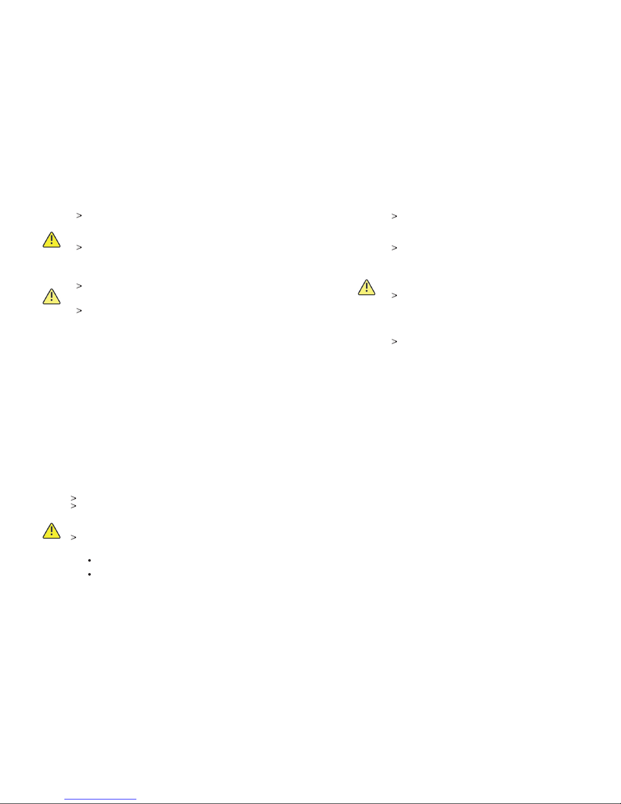
3.1. Overview
Symbol on the inverter
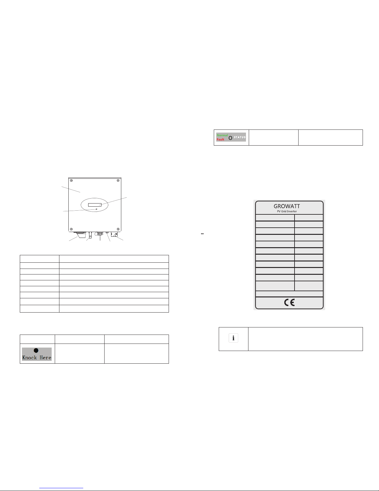
3.2. Type label
The type labe ls pro vid e a uni que id entific atio n of th e inv erte r (The type of pro duct,
Device -spe cifi c c haracte rist ics, Cer tifi cates and appr oval s). The typ e l abel s a re
on the lef t-ha nd sid e of the encl osur e.
Inform atio n
As the grid standa rds of m any coun trie s ar e in the proc ess
of impr ovin g o r upgra ding , p leas e r efer to the label on the
machin e for re fere nce of the ne west c erti ficate.
Symbol Description Explanation
Tap sy mbol Settin g the di spla y operati on
by tappi ng the L CD
Invert er sta tus sy mbol Indica tes in vert er operat ion
status
U
xxxHz
Model Name
U
DC max
I
DC max
DC range
V
AC norm
f
AC norm
P
AC norm
I
AC norm
PF
Protection Degree
Operation Ambient
Temperature
xxxxxx
xxxV
xxxV
xxxxW
xxxA
xxxx
xxxx
xxx ~ xxx°C °C
xxxV~xxxV
xxxA
IEC62109
VDE0126-1-1
G83
G
Wat erpr oof br eathabl e valv e
Positi on
F
E
D
C
B
A
AC Outpu t
PV input t ermi nals
DC switc h
State LE D
LCD
The fron t encl osur e lid
Descri ptio n
G
H
ED
C
A
B
F
H
RJ 45 Port
Page 10

12
13
More det ails abou t the t ype label a s the c hart belo w:
Mod el Name
Max i nput DC v oltag e
Max i nput DC c urren t
PV vo ltage r ange
AC gr id freq uency
Nom inal AC o utput p ower
AC no rmal ou tput cu rrent
Pow er fact or
Env ironm ental P rotec tion
Rat ing
Ope ratio nAmbi ent
tem perat ure
3.4. Transport and Store
3.4.1. Transportation
The inv ert er is tho rou ghly te sted an d in spec ted str ict ly befor e de live ry. Our
invert ers leav e ou r fa ctor y in prop er e lect rica l an d me chan ica l condit ion. Spec ial
packag ing ensu res safe a nd careful tra nspo rtat ion . H owev er, tran spor t d amage
may st ill occu r. Th e s hipp ing comp any is resp ons ible in such case s. Thor ough ly
inspec t the invert er upon de livery. Imm edia tely no tify the res ponsibl e shippin g
compan y i f y ou disc over any dam age to the pack agin g w hich indica tes that the
invert er may have be en dama ged or if you dis cove r any vis ible da mage to th e
invert er. We will be g lad t o as sist you, if re quir ed. When tran spor tin g the inverte r,
the ori ginal or equi vale nt p acka ging shou ld be use d, a nd t he maxim um layer s for
origin al car ton is s even as thi s ensu res sa fe transp ort.
3.4.2. Storage of Inverter
If yo u want t o stor age th e inve rter i n your w areh ouse , you sh ould c hoos e an
approp riat e loca tion to sto re the i nver ter.
AC no minal v oltag e
Gro watt 75 0-S
450 V
10A
50V- 450V
50H z/60H z
750 W
3.3 A
0.8 lea din g-0 .8 lag gin g
Ip6 5
-25 ...+6 0℃
230 V
Gro watt 10 00-S
450 V
10A
70V- 450V
50H z/60H z
160 0W
6.9 A
Ip6 5
-25 ...+6 0℃
230 V
3.3. Dimensions and Weig ht
The uni t mus t be s tore d in o rigi nal p ackage a nd de sicc ant m ust b e lef t in t he
packag e.
The st orag e te mper ature s houl d be alwa ys b etween -25℃ an d +6 0℃. A nd
the stor age re lati ve humidi ty can a chie ve to 100%.
If ther e ar e a batc h of inve rter s ne eds to b e st ored, the ma xim um l ayer s fo r
origin al car ton as f ollow.
The maxi mum la yers i s 11 for Gr owat t 750 -S-3 000- S
After long ter m s tora ge, local in staller or serv ice depa rtme nt of G ROWATT
should p erfo rm a com prehens ive te st bef ore insta llat ion.
3.5. The advantage of Inverter
Maximu m effi cien cy of 9 7.6%.
Wide inp ut vo ltag e range fro m 50- 550V dc.
Integr ated D C swi tch.
Sound co ntro l.
Multi co mmun ica tion p atte rn.
Easy ins tall ation.
Gro watt 15 00-S
450 V
11A
70V- 450V
50H z/60H z
200 0W
8.7 A
Ip6 5
-25 ...+6 0℃
230 V
Types
Height (H)
Width (W)
Depth (D)
Weight
Growatt 750-S
299 mm
271 mm
141 mm
6.4 kg
Growatt 1000-S
299 mm
271 mm
141 mm
6.4 kg
Growatt 1500-S
299 mm
271 mm
141 mm
6.4 kg
Growatt 2000-S
299 mm
271 mm
141 mm
6.4 kg
Growatt 2500-S
359 mm
271 mm
141 mm
9.1 kg
Growatt 3000-S
359 mm
271 mm
141 mm
9.1 kg
Mod el Name
Max i nput DC v oltag e
Max i nput DC c urren t
PV vo ltage r ange
AC gr id freq uency
Nom inal AC o utput p ower
AC no rmal ou tput cu rrent
Pow er fact or
Env ironm ental P rotec tion
Rat ing
Ope ratio nAmbi ent
tem perat ure
AC no minal v oltag e
Gro watt 20 00-S
450 V
11A
50V- 450V
50H z/60H z
200 0W
8.7 A
0.8 lea din g-0 .8 lag gin g
Ip6 5
-25 ...+6 0℃
230 V
Gro watt 25 00-S
500 V
12A
70V- 500V
50H z/60H z
250 0W
10. 9A
Ip6 5
-25 ...+6 0℃
230 V
Gro watt 30 00-S
550 V
13A
70V- 550V
50H z/60H z
300 0W
13A
Ip6 5
-25 ...+6 0℃
230 V
Page 11

All ele ctri cal in stal lations shall be done in a ccor dan ce wit h the loc al and
nation al ele ctrical c odes . Do no t remo ve th e casi ng. I nver ter co nta ins no u ser
servic eabl e part s. Refer s ervi cin g t o qual ifie d serv ice per sonn el. all wir ing
and ele ctri cal In stal lati on s houl d be co nduc ted b y a q uali fie d ser vice
person nel .
Carefu lly re move t he un it fro m its pa ckaging a nd ins pect f or ex tern al dam age.
If you fin d any im perf ections , plea se con tact your l ocal d eale r.
Be sur e th at t he i nverter s co nnec t to the ground in o rder to p rote ct prop erty
and pers onal s afet y.
The i nver ter must onl y b e o pera ted with PV gene rato r. Do not conn ect any
other so urce o f ener gy to it.
Both AC an d DC vo ltage sou rce s are t ermi nated ins ide t he PV Inv erte r.
Please d isco nnec t these cir cuit s befo re servic ing.
This unit is d esig ned to f eed power t o th e pu blic powe r gr id ( util ity) on ly. Do
not c onne ct this unit to an A C sour ce or gen erat or. Conn ecti ng Inve rter to
extern al dev ices c ould resu lt in se riou s damage to y our eq uipm ent.
When a p hotovol taic pa nel is exp osed to lig ht, it gen erates a DC volt age .
When c onne cted to this equi pme nt, a photo volt aic pan el w ill char ge t he DC
link cap acit ors.
1
Growat t inve rter
A
1
AC conne ctio n plug
B
2
Mounti ng scr ews
C
1
Instal lati on & Ope ration Ma nual
D
Item
Number
Descri ptio n
Remark s
14
15
4 Unpacking
Thorou ghly insp ect the pack aging u pon rec eive d. If a ny d ama ge t o t he c arto n i s
visibl e, or if you fin d that the inverte r unit is da mage d afte r unpa cki ng, ple ase
no tify th e sh ipp ing c omp any a nd SH ENZ HEN G ROWAT T NEW E NERG Y
TECHNO LOGY C O.,LTD imme diat ely.
Meanwh ile ple ase che ck the del iver y for com plet eness and for vis ible ex ternal
damage s of th e inv erte r. If t here a re an ything da mag ed or m issi ng, p leas e con tact
your de aler. Don 't d ispo se it s origin al pa ckag e. I f you wan t to tra nspo rt the
invert er, it is b ette r to store th e inve rter i nto the ori gina l pack age.
After op enin g the pack age, plea se check th e con tent s of th e box . It sh ould cont ain
the fol lowi ng, Ple ase che ck al l of the acc esso ries car eful ly i n the ca rton . If
anythi ng mis sing , contact y our de aler a t once.
Installation 5
5.1. Safety instructions
Danger t o life due to fire or exp losi on
Risk of bu rns d ue to h ot enclos ure pa rts
Mount th e inv erte r in su ch a wa y that it can not b e touched i nadv ert entl y.
Despit e care ful co nstruct ion, e lect rical dev ices c an cau se fires.
Do no t inst all th e inverte r on eas ily fl amma ble ma teri als an d where
flamma ble ma teri als are sto red.
Inform atio n
Though t he pac kagi ng bo x of Gro watt i nverter is d urab le, pleas e
treat the packin g box gent ly an d avo id di spos e the pack ing b ox.
In thi s pack age , ther e are inv erte r, cyst osepime nt and carton
from ins ide to o utsi de.
For the acc esso ries, the re are two kinds o f c onfi gur atio n,
please r efer t o the in verter yo u rece ive.
Energy sto red i n thi s eq uipm ent' s DC l ink cap acit ors p res ents a ri sk of
electr ic shock. E ven a fter th e u nit i s d isconne cted from the gr id and
photov olta ic pane ls, high volt ages may stil l e xist insi de the PV-In vert er. Do
not re move the cas ing unti l a t le ast 5 mi nute s after disc onne ctin g a ll p ower
source s.
Althou gh de sign ed t o mee t all safety re quir emen ts, some part s an d sur face s
of Inve rter are stil l hot d uring o pera tio n. To red uce the risk of inju ry, d o n ot
touch the heat sin k a t the b ack of the PV-In vert er or near by surf aces whi le
Invert er is op erat ing.
C
B
D
A
Page 12

1716
5.2. Selecting mounting location
This is guidanc e f or inst alle r t o choo se a suit able instal lati on loc atio n, to avoi d
potent ial da mage s to device a nd ope rato rs.
The i nsta llat ion locat ion mu st be s uita ble f or the i nverter 's wei ght a nd
dimens ions f or a lon g period ti me. (R efer t o section 3 .3)
Do no t insta ll t he i nverter on st ruct ures c onst ruc ted of f lamm able o r
thermo labi le mat erials.
Never in sta ll th e inv erte r in envir onme nt of lit tle o r no a ir fl ow, nor dust
enviro nmen t. Tha t may de rate t he eff iciency o f the co olin g fan o f the in vert er.
The Ing ress Protecti on ra te i s IP6 5 wh ich m ean s the inv erte r can be in stal led
outdoo rs and i ndoo rs.
Do not expose the inve rter to d irec t su nlig ht, in o rde r to avo id t he p ower and
eff icie ncy d erat ing ca used b y exc essi ve hea ting .
Th e h umi dit y o f t he in sta lla tio n l oca tio n sh ould b e 0 ~10 0% wi thou t
conden sati on.
The ambi ent te mper ature sho uld be b elow 4 0℃ to ensure o ptim al ope ration.
The inst alla tion l ocation m ust be f reel y and safel y to get a t all ti mes.
Vertica lly ins tall atio n an d ma ke s ure the co nnec tio n of invert er m ust be
downwa rds. N ever insta ll h oriz onta l an d av oids forwar d an d si dewa ys
tilt.( Refe r to dra wings bel ow)
Do n ot ins tal l the inver ter ne ar te levi sion ante nna or any other a nten nas a nd
antenn a cabl es.
Do not inst all the inv erte r i n l ivin g a rea, the noi se caus ed by the mach ine
may affec t on da ily li fe.
For secur ity reas ons, don ’t inst all the inve rter in plac e w here the chi ldre n
can reac h.
Don't pu t any th ings o n the inver ter.D o not co ver the inv erte r.
Invert er requ ires ad equa te cool ing spa ce. Pro vidi ng bett er vent ilat ion for
the inve rter t o ensu re the heat e scap e adeq uately.
Do not exp ose th e inve rter to dir ect su nlig ht, as this c an cau se exc essive
heatin g and th us pow er reduct ion.
Observ e the min imu m clearanc es to walls, ot her in ver ters or objects as
shown in t he dia gram b elow in ord er to gu aran tee suffic ien t heat d issi pation.
Ambien t dime nsio ns of one inv erte r
Page 13

18 19
Ambien t dime nsio ns of serie s inve rter s
There mu st be su ffic ient c lear anc e betw een th e indi vid ual in vert ers to
ensure t hat th e cool ing air of th e adja cent i nverter i s not ta ken in .
If neces sary, i ncre ase th e clea ran ce spa ces an d make s ure t here i s enou gh
fresh ai r supp ly to en sure suffi cie nt coo ling o f the in ver ters .
The inve rter c an’t i nstall to s olar izat ion,dre nch, firn l ocation . We sug gest
that the i nver ters s hould be in stal led at t he locati on wit h some c over or
protec tion
Please m ake s ure th e inv erte r is in stal led a t the r ight plac e。The in ver ter
can’t in stal l clo se to t runk
5.3. Mounting Inverter
5.3.1. Mounting bracket
DANGER
In o rder t o avo id el ectr ical shoc k or ot her in jury, in spec t exi stin g
electr onic o r plu mbin g ins tall atio ns be fore dril ling h ole s.
1.Acco rdin g to the f ollowin g dist ance t o drill two h oles o n the wa ll;
WAR NING
Fallin g eq uipm ent can caus e se riou s o r ev en f atal in jury, neve r
mount the inve rte r o n t he brac ket unle ss you are sur e t hat the
mounti ng fr ame i s rea lly f irml y mou nted on th e w all aft er
carefu lly ch ecki ng.
2.Inst all th e expl osion scr ew int o the wa ll;
Page 14

20 21
5.3.2. Mounting Inverter
Connec ting t he Sec ond Prote ctiv e Cond uctor
If the ins tall ation req uire s, the eart h term inal can be u sed to conn ect a se con d
protec tive cond ucto r or as equi pote nti al bondin g. Thi s pre vent s tou ch cu rren t
if the ori gina l prot ective co nduc tor fa ils.
Cable re quir emen t:
Earthi ng cab le cro ss-sect ion: 3 .332 m m² at maxim um
5.4. Connect switch
Separa te th e Gro watt inv erte r sec urely fr om th e gri d and the PV ge nera tor s usi ng
DC and AC Swit ch. You mus t pro vide an AC circ uit brea ker. I f Growat t DC Switch
is i nclu ded i n the d eli very of the Grow att i nver ter, i t mus t be us ed fo r operati ng th e
invert er.
5.5. Grounding
The Grow att 7 50-S -300 0-S s erie s are t ransfor merl ess i nver ters . That is wh y it ha s
no ga lvanic se para tion . D o n ot g rou nd the D C ci rcu its of the P V m odul es
connec ted to t he i nverter. Only grou nd t he m ount ing fra me o f th e PV modu les. If
you conn ect gr ound ed module s to the i nver ter, the err or mes sage " PV ISO Low" .
The inve rter m ust be conn ecte d to the AC gro unding co nduc tor of the p ower
distri buti on gri d via the gro und te rmin al (PE)
WAR NING
Becaus e of th e tran sformer less d esi gn, th e DC po siti ve po le an d
DC n egat ive p ole of PV arr ays a re not perm itte d to be grou nded .
5.6. Connect grid type
TN-C gri d suitab le
TN-S gri d suita ble
TN-C-S g rid suit able
TT gr id suitab le
Referr ing to th e foll owing figure, make the i nver ter an d expl osio n scre w
matchi ng,
Hang the i nver ter on t he explos ion sc rew
Page 15

22
23
5.7. Electrical connection
5.7.1. Safety
DANGER
Danger t o life d ue to le thal volt ages !
High vol tages whi ch ma y cau se el ectr ic sh ocks are pr ese nt in t he
conduc tive part s of the inve rter. Prio r to perf ormi ng a ny w ork on
the inve rter, d isco nnect the i nver ter on t he AC and DC sid es.
WAR NING
Danger of d amage to ele ctr onic comp onen ts d ue t o el ectr osta tic
discha rge.
Take appr opr iate ESD pre caut ions when rep laci ng a nd i nsta llin g
the inve rter.
5.7.2. Connection to the grid(AC)
Please c onne ct AC c able obey the fo llow ing p roce dure s:
1.Swit ch off AC brea ker and sec ure a gain st be ing in adverte ntly s wit ched b ack o n.
About th e AC bre aker, please re fer t o the b elow f orm .
Types Max cu rren t outp ut
Sugges ted AC sw itch s pec
4.Inse rt the stri pped and ba red c ondu ctor s L,N ,PE in to th e scr ew ter minals wi th
sign L,N ,PE o n the s ocke t element a nd ti ghte n the s crew s fir mly.
5.Push t he th read ed sleeve i nto t he soc ket e leme nt; s crew t he pr essu re sc rew
tightl y onto the th readed sl eeve ;
2. The gri d con nect ion is made usin g 3 con duct ors (L, N, and PE) ,We re com mend
the foll owin g req uire ment s for Growat t 1000 -S/ G rowa tt 15 00S/Grow att 20 00-S/Gr owat t 250 0-S/ Grow att 3 000- S.
Growat t 750- S
Model
Gro watt 75 0-S
Gro watt 15 00-S
Area(m m2)
3.3 32
3.3 32
_(mm)
_2. 05
_2. 05
AWG n o.
12
12
MAX.ca ble le ngth (m)
124
50
6.Fina lly, in sert the AC conne ctio n plu g into the AC conne ctio n rec epta cle on the
invert er.
400 Vac /10A
Gro watt 10 00-S
4.7 A
Gro watt 15 00-S
400 Vac /16A
7.8 A
Gro watt 20 00-S
400 Vac /16A
9.5 A
Gro watt 20 00-S
3.3 32
_2. 05
12 42
Gro watt 30 00-S
400 Vac /16A
14. 3A
Gro watt 30 00-S
3.3 32
_2. 05
12 28
WAR NING
You mu st ins tall a s eparate s ingl e-ph ase c ircu it-b reak er or o ther
load dis conn ecti on unit for e ach in vert er in order t o ensu re tha t the
invert er can b e safe ly discon nect ed und er load.
NOTE: The i nve rter i s equi pped w ith i nteg rate d RCM( Res idua l
curren t oper ated m onitor) and RC D(Re sidual cu rren t and pr otectiv e
device ) whic h are us ed for prev enti ng fro m being ele ctri c shoc k. An
extern al bui lt RCD i n fact is not n eces sary .
If the net work o pera tor stipu late a n exte rnal buil t RCD, you mu st
choose a r esid ual- current p rote ctiv e device th at tri gger s in the
event of r esid ual cu rrent mor e than 3 00mA .
3.Remo ve the part s of th e AC c onne cti on plu g fro m the a cces sory bag. Guid e the
pressu re scr ew, se alin g rin g, thr ead ed sle eve o ver the AC cab le
Lock the h ousi ng Unlock t he hou sing
Close th e conn ecto r
Connect the connector
socket e leme nt thr eade d sle eve se alin g ring p res sure s crew
Gro watt 25 00-S
400 Vac /16A
11.9 A
Gro watt 25 00-S
3.3 32
_2. 05
12 34
400 Vac /10A
Gro watt 75 0-S
3.4 A
Gro watt 10 00-S
3.3 32
_2. 05
12
86
Page 16

24 25
5.7.3. Connecting the PV array
5.7.3.1. Conditions for DC connection
The inve rter has 1 i ndep ende nt st ring i npu t.
The diag ram d rawi ng of D C side is sho wn as b elo w, noti ce th at the conn ecto rs ar e
in p aire d (ma le and fema le connec tors ). The conn ecto rs fo r PV ar rays a nd
invert ers ar e H4 co nnector s;
Requir emen ts for the PV modu les o f the c onne cted stri ngs:
Sa me typ e
Sa me qua nti ty of P V modu les c onne cted in ser ies
CAUTIO N
If t he invert er is n ot equipp ed wit h a DC s witc h but t his i s mand ato ry
in the cou ntry o f inst allatio n, ins tall a n externa l DC swi tch.
The foll owing lim it va lues at th e DC in put o f the i nverter m ust n ot be
exceed ed:
5.7.3. 2. Co nnectin g the P V array (DC )
DAN GER
Dan ger to li fe due to l ethal v oltag es!
Bef ore c onnec ting the P V arr ay, en sure that the D C swi tch a nd AC b reake r
are di sconn ect f rom the inve rter.N ever conn ect or d isco nnect th e DC
con necto rs unde r load.
WAR NING
Imp roper oper ation duri ng the wiri ng pro cess c an cau se fat al inj ury to
ope rator or unr ecove rable damag e to th e inve rter. O nly qu alifi ed per sonne l
can p erfor m the wir ing wor k.
Ris k of dama ge to the i nvert er.
If t he vo ltage of th e PV m odule s exce eds t he max imum input volta ge of the
inv erter, it c an be dest royed by t he ov ervol tage. This will void all warra nty
cla ims.D o not co nnect stri ngs to t he inv erter that h ave an open -cir cuit
vol tage gr eater t han the m aximu m input v oltag e of the in verte r.
WAR NING
Che ck th e con necti on ca bles of th e PV m odule s for corre ct pol arity and m ake su re th at th e
max imum input volt age o f the inver ter i s not exce eded. At an ambi ent t empe ratur e ove r 10
℃, th e open circu it vol tage o f the P V modu les sh ould n ot exc eed 90 % of th e maxi mum in put
vol tage o f the inver ter. Ot herwi se, t he max imum inver ter i nput volta ge ma y be e xcee ded a t
low a mbien t tempe ratur es.
Ty p es
M ax c ur re nt in pu t
G ro wa tt 7 50- S
1 0A
G ro wa tt 1 000 - S
1 0A
G ro wa tt 1 500 - S
1 0A
G ro wa tt 2 000 - S
11 A
G ro wa tt 2 500 - S
1 2A
G ro wa tt 3 000 - S
1 3A
5.7.4 In ver ter deman d res ponse mod es (D RMs,onl y for A ustrali a)
This ser ies in vert er has the fu ncti on of de mand resp onse m odes ,moreov er, We
use RJ45 s ocke t as inv erter DRE D conn ecti on.
5.7.4. 1 RJ4 5 socket pi n ass ignment
5.7.4. 2 Met hod of asse rti ng demand r esp onse mode s
MOD E
Rj4 5 socke t
Ass erted b y short ing pin s
Req uirem ent
DRM 0
DRM 5
DRM 6
DRM 7
DRM 8
5
6
Ope rate th e disc onnec tion d evice
Do no t gener ate pow er
Do no t gener ate at mo re than 5 0% of rat ed powe r
Do no t gener ate at mo re than 7 5% of rat ed powe r
AND S ink rea ctive p ower if c apabi e
Inc rease p ower ge nerat ion (su bject t o const raint s
fro m other a ctive D RMs)
1
5
2
5
3
5
4
5
Ass ignme nt for in verte rscap able of
bot h charg ing and d ischa rging
PIN
1
DRM 5
2
DRM 6
3
DRM 7
4
DRM 8
5
Ref Gen
6
COM /DRM0
7
/
8
/
1
→
8
Pin As signm ents Fr ont Vie w
RJ45 Soc ket
123 45678
RJ45 Plu g
Page 17

26 27
6 Commissioning
6.1. Parameters setting
Users can u se sou nd con trol f unct ion to c hang e t he d isplay langua ge a nd
lumina nce of t he dis play, en able a uto- test func tion a nd cho ose utili ty mod el.
6.1 .1. Language setting
Before ente rin g the ‘S et Languag e’ i nter face, you nee d to en ter a p assw ord as
below:
6.1.2. Set luminance of LCD display
1. If you wa nt to se t lumi nance of LC D disp lay, re peat t he ste ps as d escr ibed i n
sectio n 6.1. 1.
2. When LC D disp lays ‘ INPUT 123: 123 ’, tri ple kn ock to e nte r the se ttin g inte rfa ce.
6.1.3. Set communication address
1. If you want to set comm uni cati on address , r epea t the step s a s desc ribe d in
sectio n 6.1. 1.
2. When LC D disp lays ‘ INPUT 123: 123 ’, tri ple kn ock to e nte r the se ttin g inte rfa ce.
6.1.4. Set Queensland grid voltage range
1. If you wan t to set Que ensland gri d vol tag e ran ge , r epea t th e ste ps as
descri bed in s ecti on 6.1.1.
2. When LC D disp lays ‘ INPUT 123: 123 ’, tri ple kn ock to e nte r the se ttin g inte rfa ce.
6.1.5. Run auto test function(only for Italy)
Single kno ck t o make the di spl ay b ecom e br ight → S ingl e kn ock to “ Enable Au to
test” →D oubl e knoc k to enter “Wa itin g to start” → Sing le kno ck to s tart a uto te st. an d
then wai ting s ever al minute s for th e test r esult.
Setting…
INPUT 123:XXX
Accord ing to the LCD disp lay,y ou nee d t o i nput thr ee numb ers: 123 .You sho uld
finish s ever al ste ps as below :
1. When th e LCD st ays br ight, sin gle kn ock to ‘ Setting …’,a nd the n double kn ock to
enter ‘I NPUT 1 23:x xx’i nter fac e.
2. D oubl e kno ck to mak e the fir st nu mber fla sh, s ingl e kno ck to c hange the
number, and the firs t n umbe r y ou n eed to i npu t is ‘1’ . Do ubl e kn ock to e nter th e
second n umbe r whil e the first n umbe r was ‘1 ’.
3. When the seco nd n umb er i s f lash ing ,sin gle knock to cha nge the numb er,an d
the seco nd num ber yo u need to inp ut is ‘2 ’. Dou ble knock t o ente r the la st number
while th e firs t numb er was ‘2’.
4. When LC D disp lays ‘ INPUT 123: 123 ’, tri ple kn ock to e nte r the se ttin g inte rfa ce.
Set Language
5. Singl e knoc k to “se t languag e” →Dou ble kn ock enter “ lang uage : English ”
→S ingle kno ck to se lect t he langua ge. Aft er set ting, you n eed to w ait a fe w
second s unti l the di splay bec omes d ark, t hen the set ting w ill be s aved.
Set LCD contrast
3. Singl e knoc k to “se t LCD contr ast” →D oubl e knock to en ter “L CD con trast 2”
→ Sin gle knock to sele ct t he l umin ance . You als o ne ed t o wa it a few seco nds
after se lect ing. W hen the dis play b ecom es dark, th e chan ge is sa ved.
COM Address:xx
3. Singl e knoc k to “CO M Ad dres s: xx” →D ouble kno ck cha nge th e address t o set
mod el →Si ngle k nock t o set ad dre ss. Aft er sel ecting, y ou nee d to wai t a few
sec ond s unti l the di splay bec omes d ark, t hen the cha nge is s aved .
Model: GTXXXXXX
3. S ingl e k nock to item “Mo del: GTX XXXX X” -> Doub le knoc k t o e nter “Norm al
Volt rang e” -> Sin gle kn ock to ch ange it t o “Qld Vmax 2 55V” -> wait unt il the
displa y beco me dar k, then the i nver ter sa ved chang e.
NOTICE
This fun ctio n is onl y for Ergon E nerg y area , Queensl and, Au stra lia.
Enable Auto test
Page 18

6.2.1. Country selecting
6.2. Independent function option
Country/Regulation Name
options
VDE0126-1-1 // 0
Germany //1
UK_G83 //2
Italy
//3
France
//4
Denmark
//5
Belgium
//6
Spain
//7
Greece //8
Turkey
//9
If the countr y you want to select is not in the above list , plea se
direct ly sel ect VD E0126-1 -1.
Nether land s sele ct VDE012 6-1- 1.
NOTICE
Please f ini sh the coun try s electin g acc ording to t he fo llowing s tep s
A The LCD will quic kly swit ch t o an d st ay a t th e 'P leas e se lect ' in terface after
power on , as bel ow:
B Si ngle knoc k o n th e LC D, coun trie s w ill vary from one to a noth er a long th e
above l ist ord er. b elow act s as an ex ampl e, a nd G erma ny i s the sec ond
select ion.
C W hen you need to sel ect any of thes e c ountrie s, you can Doub le knoc k t o
enter th e next i nter face. Her e we sel ect It aly as an exa mple , as bel ow:
D Wh en the c ountry ar rive s at It aly, Do uble k nock to ent er the two op tion s 'YES'
and 'NO' , and th e curs or stays at ' NO' in d efau lt, as belo w:
E Si ngle k noc k to se lect ' YES', as be low :
F D ouble kn ock t o con firm your sel ecti on, L CD wi ll di spl ay 'S elec t OK' with the
countr y name i n the be low, as belo w:
28 29
Inform atio n
If you hav e orde red th e inverte r with s peci fic count ry set ting s, the
parame ters h ave be en preset i n fact ory an d you don't n eed to
operat e this s tep an y more.
This ser ies in vert er in Hunga ry mar ket ha s not count ry set ting s.
When the P V pane ls are c onnecte d and th eir ou tput volt age is g reat er than 70V dc
but the AC gr id is no t yet co nnected , inve rter w ill start u p auto mati cally. If it is t he
first ti me to po wer on t he invert er aft er ins tallati on, yo u may ne ed to selec t a
specif ic cou ntry. Othe rwis e, th e inte rfac e will s tay a t the ‘P leas e Sele ct’ in terf ace
all the ti me. Th ere ar e elev en opt ion s to sel ect, a s the li st be low.
Page 19

30 31
if you stil l sing le knoc k at the inte rfac e a s E, the curs or will g o t o
'NO' ag ain as D, the n if you doub le k nock , th e displa y will sw itch to
the inte rfac e as C.
Inform atio n
G Wh en the sele ctio n is su ccessfu l, the inve rter will r eboo t aut omat ically
If y ou hav e sel ecte d and c onfi rmed an unw ante d cou ntry negl ectf ul,
please con tact Gro watt for spe cif ic so ftwa re to cle ar an d res et
again.
Inform atio n
6.2.2.Auto test
6.2.2.1.Spec of the CEI 0-21 SPI
SPI func tion:t he in tegr ated SPI co nsi sts of 4 volt age l evel p rot ecti on and 2
freque ncy ra nge p rote ctio n. Th e prot ection lo gic i s as fo llow s:
6.2.2.2.Autotest
Connec t the In vert er and the PC b y RS23 2;
Power o n the inve rter, chec k the inv erte r com addr ess, and wait the i nver ter t o
connec t to gri d;
Open the P C sof twar e Shi neBu s, and sele ct page “5 Aut o Test”; set th e PC co m
port(C OM) an d the in verter co m addr ess( Inv Add);
Click bu tton “ Test” to te st the S PI fun ction;
Wai t the te st fin ish, ther e are 8 le vels t esting;
The te st resu lt d ata is s aved in the “Auto t est rep ort of xxxx xx . txt ” un der the
Softwa re ins tall d irectio n;
Page 20

32
33
Test fail co ndit ion:
Condit ion
Reason Sugges tion
Test Stop Commun icat ion lo se or inver ter
occur ot her fa ult wh en testin g
Check th e comm unic ation or
check th e inve rter s tate
Test fail The trip v alue o f the te st result i s
not in the l imit o f the sp ec
Check th e grid s tate , make sure
the grid i s stab le, an d retest
6.2.3. GFCI function
GFCI is sho rt for Gro und- Faul t Circuit In terr upte r which is used for pr eventin g
from bei ng el ectric sh ock . The i nver ter i s equ ippe d wit h int egra ted R CD (R esid ual
Curren t P rote ctive Devi ce) and RCM (Re sidu al Cur rent Ope rate d Moni tor) . T he
curren t se nsor wil l de tect the volu me o f the l eaka ge curr ent and comp are it with
the pre- set value . If the leak age curre nt is above t he permit ted ra nge, the RC D wil l
discon nect t he inv erter fro m the AC lo ad.
6.2.4. PV isolation detection
The ISO func tion a pro tec tion mech anis m. Th e invert er me asur es the re sist ance s
betwee n both t he pos itive pol e and ne gati ve pole of PV p anel a nd ear th.
Either o f the measu red va lue i s lowe r than the li mit, the P V inverte r will n ot
connec t to grid , th e o utpu t re lay will stay open , an d sh ow 'PV isol ation l ow'. The
limite d valu e is det ermi ned by t he sta nda rds. The fir mwar e sett ing of o ur PV
invert ers is 5 00Ko hm.
The si mpli fie d pr inci ple of t he isol ation r esis tan ce m easurem ent is desc ribed a s
below:
6.3. LCD display
In the low er cent er of inve rte r t her e i s the LCD dis play. We can che ck inve rter
runnin g stat us, e tc. on the LC D scr een. Item s display ed can be cha nged by knock;
you can al so cha nge so me invert er par amet ers by knoc k.
6.3.1. General LCD display
Starti ng-u p di spla y se quen ce , once the PV p ower is su ffic ient , inv ert er displ ays
inform atio n as sho wn in the flo w char t as fol low:
Power on LCD display
6.3.1.1. The first line of LCD
Standb y When the i nput v olta ge falls to 7 0V,inv erter
will dis play s tand by.Th e inve rte r will s hut
down whe n inpu t volt age is lowe r than 6 0V.
Connec t in xxS
System c heck ing
Reconn ect in x xS
System c heck ing
Power: x xxx. xW
Invert er out put po wer in norm al mod e.
DISPLAY CO NTEN T
REMARK
STATU S
Wai ting
When the i nput v olta ge is betwe en 70V a nd
80V duri ng sta rt up, i nverter w ill di spla y
‘waiti ng’
Wai ting
Connec t OK
Connec ting t o the gr idNormal
Error: x xx
System f ault
Fault
Auto Tes ting
Protec ting f unct ion
Auto Tes t
Progra mmin g Progra mmin g
Firmwa re upd ate
Page 21

34 35
Inform atio n
In fault mo de, there c an b e d ifferent erro r me ssages disp laye d
in t he LCD du e to d iffe rent faul ts. P lease re fer t o Cha pter 10 fo r
refere nce. The f irst l ine o f LCD d isplay ca n be chang ed by k nock
on the LCD scr een. The sec ond line aut oma tica lly chan ges in
the inte rval o f 2 or 4 sec onds as abo ve Table .
6.3.1.2. The second line of LCD
CYCLE DI SPLAY DISPLAY TI ME/S
REMARK
Model nu mber o f the in verter
2
Firmwa re ver sion o f the inver ter
2
Serial n umbe r, whic h is also sho wn on
2
Energy g ener ated t oday.F or acc urat e
energy t o get th e FIT pa ymen t, ple ase
refer to y our me ter
4
4
PV volta ge (PV ) and Bu s voltage ( B)
4
Grid vol tage ( AC) an d frequen cy (F)
4
Enable a uto te st fun ction
4
Total gene rate d ener gy since in stal lati on.
For accu rate e nerg y to get the FI T
paymen t, ple ase re fer to your m eter
Settin g stat us
4
Commun icat ion ad dress of th e inve rter
4
6.3.2. LCD control
To sa ve p ower, the L CD d ispl ay's bac kgr ound lig ht will t urn off auto mati call y in
10 sec onds . Si ngle knoc k will turn on t he b ackg round l ight . Th e di spla y on the
invert er can b e cont rolled by k nock ing th e sound con trol p anel i n front of it .
6.4. Communication
A de tail ed wi ring dia gram an d ins tall ati on de scri ption ca n be fou nd in th e
commun icat ion mo dule manu al.
6.4.1. RS232 (standard)
RS 2 32 is u sed f or single p oint comm unicati on. Use a RS 2 32 ca ble t o
connec t fro m inv erter's RS 23 2 por t to comp uter 's RS 232 port , or t o connec t
to a R S232 -to -USB c onverte r, then conn ect to comp uter 's US B port. And th en
run Shin eNet t o moni tor the inv erte r.
6.4.2. WIFI (Optional)
WiFi mod ule (I t is ava ila ble fr om Gro watt .)c an be us ed as an o pti onal m onit orin g
scheme . T he ways to in stal l the WIF I modu les and to mo nito r your in vert ers
refer to t he WIF I modu le manual .
Settin g...
Power : 20 15.0 W
PV : 250V B: 3 60V
Page 22

6.5. Commissioning the inverter
1. If the in vert er con nects wit h PV pan el arr ays and the i nput v olta ge is highe r than
70Vdc, whil e the AC grid is no t con nected yet, LCD will displa y mes sage s in o rder
as below :
‘Ser N O: x xx' ->'x xxxx '->' FW vers ion' ->'Waiti ng'- >'N o AC connect ion' , the d ispl ay
repeat s 'NO Ut ilit y' and LED wi ll be re d.
2. Turn o n the A C bre ake r or c lose the fuse betw een i nve rter and g rid, the syst em
will ope rate n orma lly.
3. Unde r nor mal oper atin g co ndit ions , th e LCD displays 'Pow er: xxx. x W' at St ate
info, th is is th e powe r fed into gr id. LE D turn s green.
4. Finis h comm issi oning.
6.6.1. ShineNet
ShineN et is a mon itor ing s oftware appl ied t o mon itor Grow att inve rter s via RS23 2
port o r B luet ooth m odul e. Wit h t he s peci al des ign ed f unction s an d f rien dly
compac t UI, it ca n co mpre hens ivel y me et u sers ' re quir eme nts f or s ystem
monito ring a nd bri ng unprec eden ted us er experi ence .
6.6. Monitoring tool instructions
36
37
Featur es:
Inform atio n
Users ar e abl e to m onit or th e i nve rter aft er th e set ting of
softwa re. Detailed info rma tion abou t s etting and func tion s r efer
to the Shi neNE T Manu al.
Y o u c a n d o w n l o a d t h e S h i n e N e t Y N 2 . 0 f r o m :
ftp:// 113.1 06.5 8.16 9, th e use r name is ftp gue st and Pass word i s
ftpgue st.
Sh ine Net m ay b e u pgr ade d f or b ett er f unc tio n o r u ser
experi ence , plea se refer to t he act ual so ftware ve rsio n.
6.6.2. ShineVision
ShineVi sio n is a w irel ess monitori ng d evice, whic h c onsi sts of a powe r m onit or
and a num ber of trans mitt ers, a nd o ne s hin evis ion ca n mo nito ring 1 to 6
invert ers. The t ran smit ters transmi t the run ning data col lect ed f rom p hoto vol taic
invert ers to t he m oni tor and disp lay the data onto the moni tor scre en, includin g
data of ge nera ted energ y, the gr oss ge nera ted e nerg y and th e gen erat ion in come
obtain ed fr om th e ab ove- ment ione d da ta th roug h so me si mple ca lcul atio ns,
indoor t empe ratu re, date an d time , as wel l as CO2 emis sion s.
Monito r and re cord c urrent da ta and o f inve rters.
Record h isto rica l data.
Monito r and re cord e vent info rmat ion of i nverter
Connec t com pute r and inve rte r via RS23 2 and RS48 5 por t (wi re conne ctio n)
or Bluet ooth m odul e (wirele ss con nect ion).
Remote a cces s avai lable for l ocal a rea ne twork.
Featur es:
Monito r and tr ansm itter com muni cate v ia wirele ss com muni cation te chno logy.
Extern al tra nsmi tter, with I P65 wa terp roof and du stpr oof.
A mo nito r can si multane ousl y comm unicate w ith si x tran smitter s.
Commun icat ion di stance be twee n moni tor and tra nsmi tter : 3 0 meter.
Power su pply o ptio n: built- in bat tery s lot, an ext erna l DC pow er supply.
Easy ins tall atio n, and conv enie nt to us e it.
Inform atio n
The Mon itor sho uld be k ept ind oor. F or detai led i nfor mation,
please r efer t o Shin eVis ion Ma nua l.
Page 23

38 39
6.6.3. ShineWe bBo x
It is a cost -eff ecti ve a nd c omp act moni tori ng d evice, spec iall y de sign ed for sola r
power plant. Using stable Linux oper atin g syst em with hi gh-s pee d CPU, it can
smartl y re cord your system featu res. Shin eWeb Box Prov ides loca l st orag e, e asy
wirele ss and T CP/I P conf igur atio n, an d pres ents p lant d ata o ver In tern et.
A multi-f unct iona l and h igh- perf ormance c ommu nica tio n data l ogge r; Ke ep use r
inform ed of th e syst em’s s tatu s at an y time .
Ma ssi ve st ora ge wi th fl exi ble pa ram ete rs s ett ing , s yst em i nfo rma tio n
manage ment , erro r prompt an d reco rd.
Collec ts data and uplo ads inform atio n over th e interne t in nea r real-ti me to
Growat t Shin e Serv er platfo rm.
Featur es:
Startup and Shutdown the Inverter 7
7.1. Start up the Inverter
Connec t the li ne cir cuit brea ker fr om sin gle phase .
Tur n on the DC switc h, a nd t he i nver ter wil l st art auto mati cally w hen the inpu t
voltag e is hig her th an 70V.
Note:F or Gro watt 7 50-S,th e star t volt age is 50V
7.2. Shutdown the Inverter
Discon nect the line cir cuit brea ker from single ph ase and p reve nt i t from be ing
reacti vate d.
Tur n off th e dc swi tch.
Check th e inve rter o peratin g stat us.
Wai ting u ntil L ED, displ ay hav e gone o ut, the inv erte r is shu t down.
1.
2.
3.
4.
1.
2.
Page 24

8 Operation Modes
8.1. Waiting mode
When the P V vo ltag e is high er t han 70V, Inve rter will be p ower ed u p, a nd ente rs
“waiti ng” mo de.
In this mode, in vert er w ill chec k th e sy stem pa rame ters . I f th e sy stem is norm al,
and PV vol tage i s high er than 80V dc, th e inve rter will a ttem pt to co nnect to gr id.
8.2. Normal mode
In t his mo de, t he in vert er works no rmal ly an d LED t urns gree n.
Inform atio n
The inv erte r st arts up a utom atic ally whe n the DC p ower fro m the
PV panel i s suff icie nt.
8.3. Fault mode
The int erna l in tell igen t co ntro ller can continuo usly mon itor and adju st t he sy stem
status . If inver ter f inds any une xpected con diti ons s uch a s sys tem f ault and
invert er fa ult, the faul t inf orma tio n wil l be d isplaye d on t he LC D. I n fau lt mo de the
LED turn s red.
Inform atio n
Detail ed fau lt in form atio n ref ers t o chap ter 1 0 Troub les hoot ing.
8.4. Shutdown mode
Invert ers au tomatic ally s top r unni ng du ring p eriods of lit tle or no su nlight. I n
shutdo wn mo de th e in vert ers t ake n o po wer f rom t he grid a nd pa nel, and the L CD
and LED tu rns of f.
Inform atio n
If the PV stri ng DC vol tage is too low (≤6 0 V dc) or DC swi tch
open, th e inve rter w ill also tu rn to sh utdo wn Mode
Note:F or Gro watt 7 50-S,th e PV low v olta ge is less th an 50V.
Whenev er th e DC v olta ge is high er th an 80 Vdc , inv erte r con vert s pow er to grid
as gener ated b y the PV p anels;
Whenev er th e DC volta ge is lowe r tha n 70V dc, t he in vert er wi ll wo rk in stan dby
state and attempt to connect the grid . I n w aiting sta te the inve rter con sume s
just enou gh powe r g enerate d b y t he PV pane l t o moni tor the inte rnal sys tem
status ;
40
41
Maintenance and Cleaning 9
9.1. Checking heat dissipation
If the inve rter regu larl y reduce s its out put powe r du e to high temp erat ure, plea se
improv e the he at dis sipatio n cond itio n. Maybe yo u need t o clea n the heat si nk.
9.2. Checking the DC switch
Checki ng ex tern all y vis ible dam age a nd di sco lora tion of t he DC swit ch. If th ere is
any visi ble dam age to th e DC Disc onnect, or vi sibl e dis colo rati on, contac t the
instal ler.
Once a ye ar, tu rn th e rotary swit ch fr om th e On p osit ion t o the Off p osit ion 5 time s
in su cces sio n. This c lean s the co ntac ts of the r otar y swit ch and p rolo ngs th e
electr ical e ndur ance of the D C Disc onne ct
9.3. Cleaning the Inverter
If t he in vert er is d irt y, clea n the e ncl osur e lid , the d ispl ay, an d the L EDs u sing only
clean wat er a nd a cl oth. Do no t us e an y cl eani ng a gents (e.g. so lven ts o r
abrasi ves) .
Page 25

10 Trouble Shooting
Someti mes, the PV in verter d oes not w ork norm ally, we recom mend the foll owin g
soluti ons for com mon t roubles hoot ing. The fo llowing t abl e can h elp t he te chni cian
to under stan d the pr oblem and t ake ac tion .
10.1 Warnings(W)
War ning s(W) identif y th e curre nt s tatus o f th e G rowa tt i nve rter. Warni ngs do n ot
relate to a fa ult. W hen a (W) w ith a num ber af ter it ap pear s in the di spla y, it
indica tes a Warni ng Co de a nd is usu ally clea red t hrou gh a n orderl y shu tdown/r eset or a self corr ecti ve a ctio n pe rfor med by th e in vert er. See th e (W ) cod es i n the
follow ing ta ble.
Error message Description Suggestion
No AC Conne ctio n
No utili ty gri d
connec ted or u tili ty
grid pow er fai lure .
1.Chec k AC wi ring.
2.Cont act Gr owat t.
AC V Outra nge
Utilit y grid v olta ge is
out of per miss ible
range.
1.Chec k grid v olta ge.
2.If the e rror m essa ge still ex ists
despit e the gr id vol tage bein g with in
the tole rabl e rang e, contac t Grow att.
AC F Outra nge
Utilit y grid f requ ency
out of per miss ible
range.
1.Chec k grid f requ ency.
2.If the e rror m essa ge is displ ayed
despit e the gr id fre quency be ing wi thin
the tole rabl e rang e, contac t Grow att.
Over Tem pera ture
Temperat ure ou tran ge
1.check t he inv erte r operati on sta te
2.If the e rror m essa ge is displ ayed s till ,
please c onta ct Gro watt.
PV Isola tion L ow
Insula tion p robl em
1.Chec k if pan el enc losure gr ound
proper ly.
2.Chec k if inv erte r ground pr oper ly.
3.Chec k if the D C brea ker gets we t.
4.If the e rror m essa ge is displ ayed
despit e the ab ove ch ecking pa ssed ,
contac t Grow att.
Output H igh DC I
Output c urre nt DC
off set to o hig h
1.Rest art in vert er.
2.If err or mes sage s till exis ts,
contac t Grow att.
42 43
Residu al I Hig h
Leakag e curr ent
too high
1.Rest art in vert er.
2.If err or mes sage s till exis ts,
contac t Grow att.
PV Voltag e High
The DC inp ut
voltag e is exc eedi ng
the maxi mum to lera ble
value.
Discon nect t he DC sw itch
immedi atel y.
Auto Tes t Fail ed Aut o test d idn' t passed.
Restar t inve rter
Inform atio n
If the sug gest ions d o not work, p leas e conn ect to the Gr owat t.
10.2 Errors(E)
Errors (E) code s iden tify a pos sibl e e quipmen t f ailu re, fau lt or inco rrec t i nverter
settin g o r c onfi gura tion. Any and all attempt s t o c orre ct or clea r a fau lt must be
perfor med b y qua lif ied p erso nnel. Typical ly, th e (E) code can be cl eared on ce th e
cause or f ault is r emov ed. Some of the ( E) c odes , Er ror as indic ated in t he t able
below, may indi cat e a fatal erro r and requ ire you to cont act the sup plier or the
Growat t to rep lace a n ew one.
Error co de
Descri ptio n Sugges tion
Error: 1 01
Commun icat ion fa ult Slave
proces sor ca n't re ceive dat a
from Mas ter pr oces sor.
1.Rest art in vert er
2.If err or mes sage s till exis ts,
contac t Grow att.
Error: 1 02
Consis tent f ault . Data
receiv ed by Ma ster a nd Slave
proces sor ar e diff eren t. The
reason c an be ut ilit y grid
voltag e or fre quen cy change
freque ntly. .
1.Rest art in vert er.
2.If err or mes sage a ppears
freque ntly o r erro r message
still ex ists a fter r eplacem ent,
check ut ilit y grid . If you requ ire
help, co ntac t Grow att.
3.If err or mes sage s till exis ts,
contac t Grow att.
Error: 116
EEPROM f ault
Contac t Grow att.
Error: 117
Relay fa ult
Contac t Grow att.
Error: 118
Init mod el fau lt
Contac t Grow att.
Error: 119
GFCI Dev ice Da mage
Contac t Grow att.
Error: 1 20
HCT fa ult
Contac t Grow att.
Error: 1 21
Commun icat ion fa ult.
Master p roce ssor c an't
receiv e data f rom Sl ave
proces sor.
1.Rest art th e inve rter
2.If err or mes sage s till exis ts,
contac t Grow att. .
Error: 1 22
Bus volt age fa ult
Contac t Grow att.
Page 26

Decommissioning 11
11.1. Dismantling the Inverter
1. Disco nnec t the in verter as d escr ibed i n section 7 .
2. Remov e all co nnec tion cabl es fro m the in verter.
CAUTIO N
Danger o f burn i njur ies due to ho t encl osur e parts!
Wai t 20 minu tes be fore d isas semb ling until the ho usin g
has cool ed dow n.
3. Screw o ff all p roje ctin g cabl e gla nds.
4. Lift th e inve rter o ff the b rack et an d unsc rew th e brac ket s crew s.
11.2. Packing the Inverter
If p ossi ble, alwa ys pac k the i nver ter i n its origi nal ca rton and se cure it wit h ten sion
belts. If it is no longe r av aila ble, yo u ca n al so u se a n equiv alen t ca rton . Th e box
must be capable of being clos ed c ompl etel y an d mad e to supp ort both the weig ht
and the si ze of th e inve rter.
11.3. Storing the Inverter
Store th e inve rter i n a dry p lace w here a mbient te mper atur es ar e alwa ys bet ween 25°C and + 60°C .
11.4. Disposing of the Inverter
Do n ot dispos e of fa ulty in ver ters o r a cces sor ies to get her wi th
househ old wast e. P lea se acco rdan ce with the disp osa l regul atio ns for
electr onic waste wh ich appl y at the i nsta lla tion site at th at ti me. Ensu re
that the old u nit a nd, w here appl icable, any ac ces sori es ar e dis pose d of
in a prope r mann er.
44 45
12Technical Data
12.1. Specification
Model
Gro watt
100 0-S
Gro watt
150 0-S
Input da ta(D C)
Max . DC powe r
130 0W 180 0W
Max . DC volt age
450 V 450 V
Sta rt volt age
80V 80V
PV vo ltage r ange
70V- 450V
70V- 450V
MPP w ork vo ltage
ran ge/ nom inal
vol tage
70V- 450V
/25 0V
70V- 450V
/18 0V
Ful l load dc v oltag e
ran ge
175 V-400V
110V- 400V
Max . input c urren t
10A
10A
Max . input c urren t
per s tring
10A 10A
Num ber of in depen dent
MPP t rack ers / str ings pe r
MPP t rack er
1 / 1
1 / 1
Output ( AC)
Rated AC ou tput
power
100 0W 1 600W
Max. AC pow er
100 0W 1 650W
4.7 A
Max. out put
curren t
7.8 A
AC nomin al
voltag e; ran ge
AC grid
freque ncy; r ange
Power fa ctor
THDI
<3%
<3%
AC conne ctio n
Gro watt
200 0-S
230 0W
450 V
80V
70V- 450V
70V- 450V
/36 0V
200 V-400V
11A
11A
1 / 1
200 0W
200 0W
9.5 A
<3%
Gro watt
300 0-S
340 0W
550 V
80V
70V- 550V
70V- 550V
/36 0V
250 V-500V
13A
13A
1 / 1
300 0W
300 0W
14. 3A
220 V/230 V/240 V; 180Va c-280 Vac
50, 60H ; ±5 Hzz
<3%
Sin gle pha se
Gro watt
250 0-S
290 0W
500 V
80V
70V- 500V
70V- 500V
/36 0V
220 V-450V
12A
12A
1 / 1
250 0W
250 0W
11.9 A
<3%
Gro watt
750 -S
970 W
450 V
55V
50V- 450V
55V- 450V
/18 0V
80V- 400V
10A
10A
1 / 1
750 W
750 W
3.4 A
0.8 leadi ng-0. 8lagg ing
<3%
Page 27

46 47
Eff icie ncy
Protec tion d evic es
Genera l Data
Ope ratin g tempe ratur e
ran ge
–25°C ... +60°C (-13...+140℉) with derating above 45°C /113℉
Altitu de
200 0m(65 60ft) w ithou t derat ing
Max. effi cie ncy
97. 4% 9 7.4%
Euro wei ghte d
eff icie ncy
96. 5% 9 7%
MPPT effi cien cy
99. 5% 9 9.5%
DC re verse p olari ty
pro tecti on
yes yes
DC sw itch ra ting fo r
eac h MPPT
yes yes
Out put ove r curre nt
pro tecti on
yes yes
Out put ove r volta ge
pro tecti on-va risto r
yes yes
Gro und fau lt
mon itori ng
yes yes
Gri d monit oring
yes yes
Int egrat ed all - po le sens itive
lea kage cu rrent m onito ring un it
yesyes
Dimens ions ( W / H / D)
in mm
271 /299/ 141 2 71/29 9/141
Wei ght
6.4 KG
6.4 KG
Noise em issi on (ty pical)
Self-C onsu mpti on
night
< 0.5 W< 0 .5 W
Coolin g conc ept
Nat ural Nat ural
Topology
tra nsfor merle ss
Enviro nmen tal Pr otectio n
Rating
Ip6 5 Ip6 5
Relati ve hum idit y
100 % 100 %
Featur es
Interf aces : RS23 2/Wifi
yes /opt
DC conne ctio n
H4
H4
AC conne ctio n
con necto r
con necto r
Displa y
LCD
LCD
War rant y: 5 yea rs
/ 10 years
yes / opt
yes / opt
CE, V DE 0126 -1-1, V DE-AR -N-41 05,IE C 62109 , G83,
AS4 777, NB T3200 4-201 3, EN50 438, CE I 0-21, INMET RO
yes /opt
Certif icat es and a pproval s
12.2. DC connector info
DC conne ctio n H 4
97. 4%
97%
99. 5%
yes
yes
yes
yes
yes
yes
yes
271 /299/ 141
6.4 KG
< 0.5 W
Nat ural
Ip6 5
100 %
H4
con necto r
LCD
yes / opt
yes /opt
97. 6%
97. 3%
99. 5%
yes
yes
yes
yes
yes
yes
yes
271 /359/ 141
9.1 KG
< 0.5 W
Nat ural
Ip6 5
100 %
H4
con necto r
LCD
yes / opt
yes /opt
97. 6%
97. 1%
99. 5%
yes
yes
yes
yes
yes
yes
yes
9.1 KG
< 0.5 W
Nat ural
Ip6 5
100 %
H4
con necto r
LCD
yes / opt
yes /opt
97. 2%
96%
99. 5%
yes
yes
yes
yes
yes
yes
yes
271 /359/ 141
271 /299/ 141
6.4 KG
≤ 25 dB (A)
< 0.5 W< 0.5 W
Nat ural
Ip6 5
100 %
yes /opt
H4
con necto r
LCD
yes / opt
12.3. Torque
Enclos ure li d scre ws 7kg.cm
Shell an d RS23 2 scre ws 7kg.cm
AC termi nal 6kg.cm
Additi onal g roun d screws 20k g.c m
Page 28

48 49
13 PV System Installation
13.1. Single inverter
13.2. Multi inverters
Compliance Certificates 14
Growat t750 -S-3 000-S
Certif icat es
14.2. Download address
www.gin vert er.com/Do wnlo ad.a spx
14.1. List
15 Contact
If yo u h ave te chni cal pr oble ms abo ut our p rodu cts, c onta ct the G ROWATT
Servic elin e. We need the fol low ing info rmation in orde r to provide you with th e
necess ary as sist ance:
Invert er typ e
Serial n umbe r of the i nverter
Event nu mber o r disp lay messa ge of th e inve rter
Type a nd num ber o f PV mod ules c onne cte d
Option al equ ipme nt
Declar atio n
CE, V DE 0126 -1-1, V DE-AR -N-41 05,IE C 62109 , AS4 777, N BT320 04-20 13,
EN5 0438, C EI 0-21 ,INME TRO
G83
 Loading...