

Page 1
service@ginverter.com
GR - UM - 001 - 09
GROWATT NEW ENERGY CO.,LTD
No. 2 8 Gua nghui R oad, Lo ngten g Commu nity,
Shi yan, Ba oan Dis trict , Shenz hen, P.R. C hi na
Page 2
Congratulations on choosing our Grid PV Inverter, Our Grid PV Inverter are a highly
reliable products due to their innovative design and perfect quality control.Such invert ers
are used in high demand, grid-linked PV systems. This manual contains important
information regarding installation and safe operation of this unit. Be sure to read this
manual carefully before using. If you encounter any problems during installation or
operation of this unit, first check this manual before contacting your local dealer or
representative . Instructions inside this manual will help you solve most installation and
operation difficulties.
CONTRNT
INSTALLATION
2.1 Installation manual
2.2 Fixed on the wall
2.3 Connect to the grid (AC utility)
2.4 Connect to PV panel (DC input)
2.5 Checking
2.6 System diagram
MODES OF OPERATION
3.1 Normal mode
3.2 Fault mode
3.3 Shutdown mode
3.4 Sound control LCD display
INVERTER STATUS
COMMUNICATIONS
5.1 Communications software instructions
5.2 Monitor
5.3 Detailed information
5.4 RS 485 cable connection
TROUBLE SHOOTING
SPECIFICATIONS
Content 1
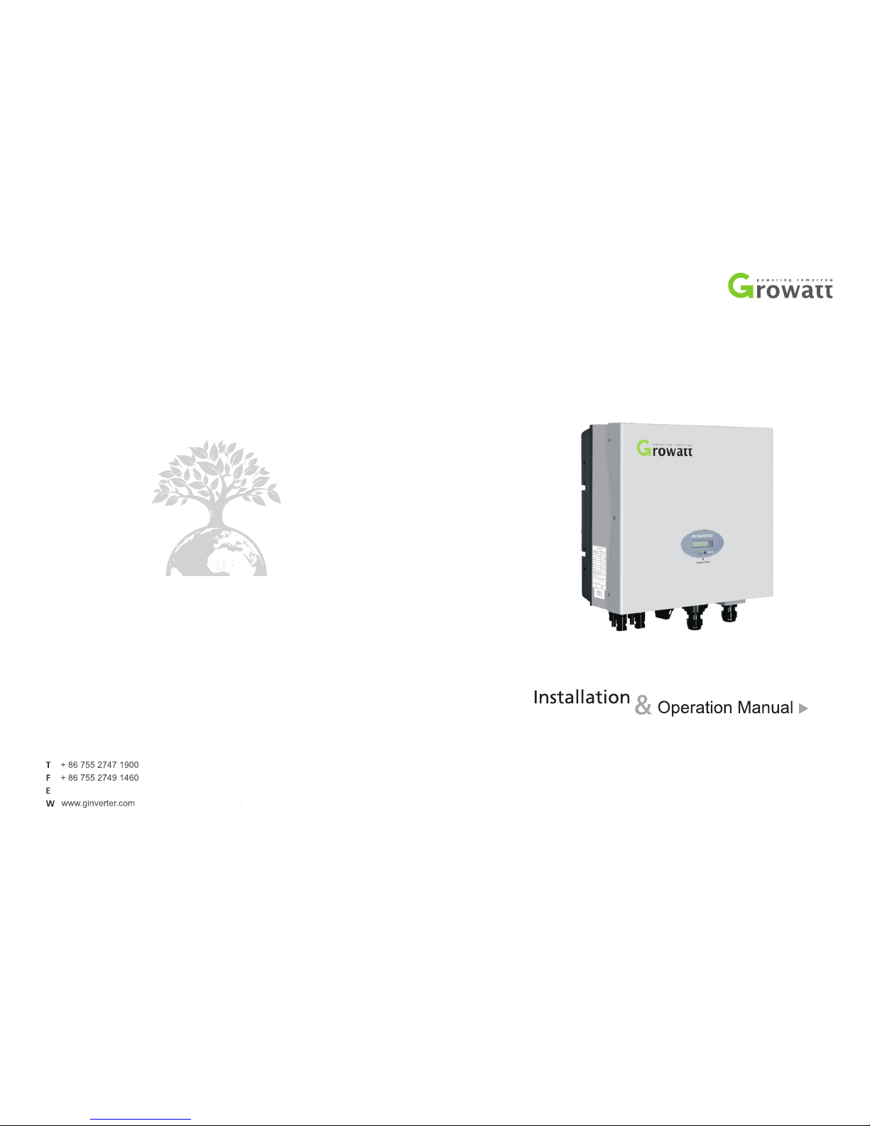
Design Overview
Front Overview
1
Page 3
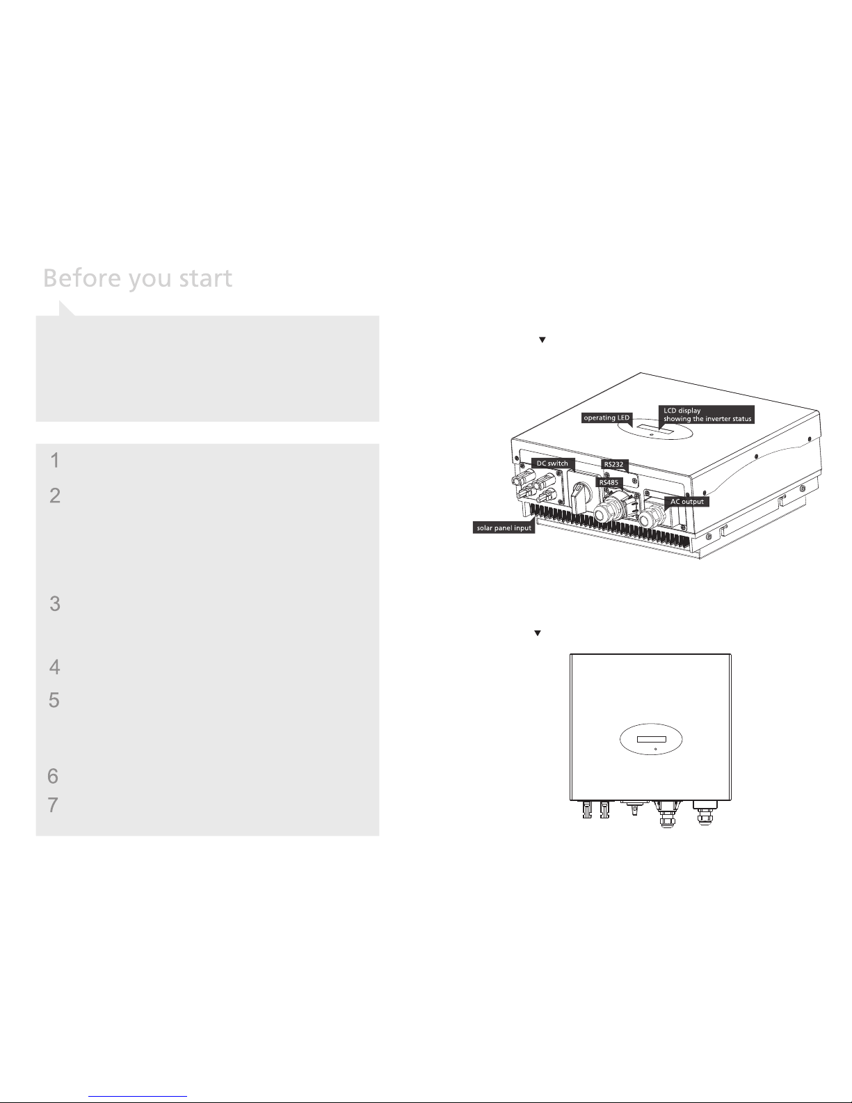
Bottom Overview
Open ing the pack age
Item
Name
Ouantity
1
2
3
4
5
6
7
8
9
10
Solar inverter
Mounting frame
Mounting scre ws
Safety-lock screw s
Mounting frame scre ws s le ev e
AC socket
AC socket assembly scre ws
Installation & Operation manual
RS485 waterproo f de vi ce
RS485 waterproo f de vi ce a ss em bl y sc re w
1
1
6
4
6
1
4
1
1
4
After opening the package, please check the contents of the box. It should contain
the following:
32
Installation 2
2.1 In stallati on manual
E
A
B
C
Do no t re mo ve t he c as in g. I nv er te r contains no use r se rv ic ea bl e
parts. Refe r serv ic in g to q ua li fi ed ser vi ce per so na l. All wiri ng and
electrical in st al la ti on sh ou ld be con du ct ed by a qu al if ie d ser vi ce
personnel and must meet national requirements of AS/NZS 3000.
Both AC and DC vo lt ag e sou rc es ar e ter mi na te d ins id e the PV
Inverter. Pl ea se d is co nn ec t th es e ci rc ui ts b ef or e se rv ic in g.
When a ph ot ov ol ta ic pa ne l is exposed to light, it ge ne ra te s a DC
voltage. When conn ec te d to t hi s equi pm en t, a p ho to vo lt ai c pa ne l
will charge the DC link capacitors.
Energy st or ed in this eq ui pm en t’s DC link ca pa ci to rs pr es en ts a ris k
of el ec tr ic shoc k. Even afte r th e un it is disconnected f ro m th e gr id
and ph ot ov ol ta ic pa ne ls , h ig h v ol ta ge s m ay st il l e xi st in si de th e P VInverter. Do no t remove the casing un ti l at le as t 10 mi nu te s afte r
disconnecting all power sources.
This un it i s de si gn ed t o fe ed p ow er t o th e pu bl ic p ow er t o th e
public grid (utility) only. Do n ot c on ne ct t his unit to an AC source or
generator. Co nn ec ti ng Inv er te r to ex te rn al dev ic es cou ld res ul t in
serious damage to your equipment.
Carefully remove t he un it fr om it s packing and in sp ec t f or ex te rn al
damage. If you fi nd an y imp er fe ct io ns , ple as e con ta ct yo ur lo ca l
dealer.
Although d es ig ne d t o me et al l safety re qu ir em en ts , s om e parts a nd
surfaces of In ve rt er a re s ti ll h ot during o pe ra ti on . To re du ce t he r is k
of in ju ry, do n ot touc h the h ea t si nk at th e ba ck of th e PV- In ve rt er
or nearby surfaces while Inverter is operating.
D
G
F
Page 4
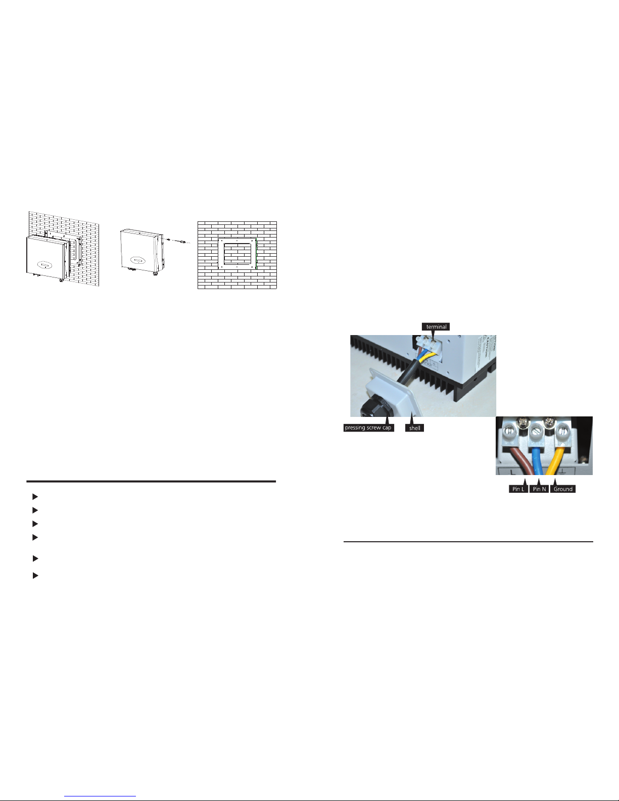
Image 1
Image 2
Image 3
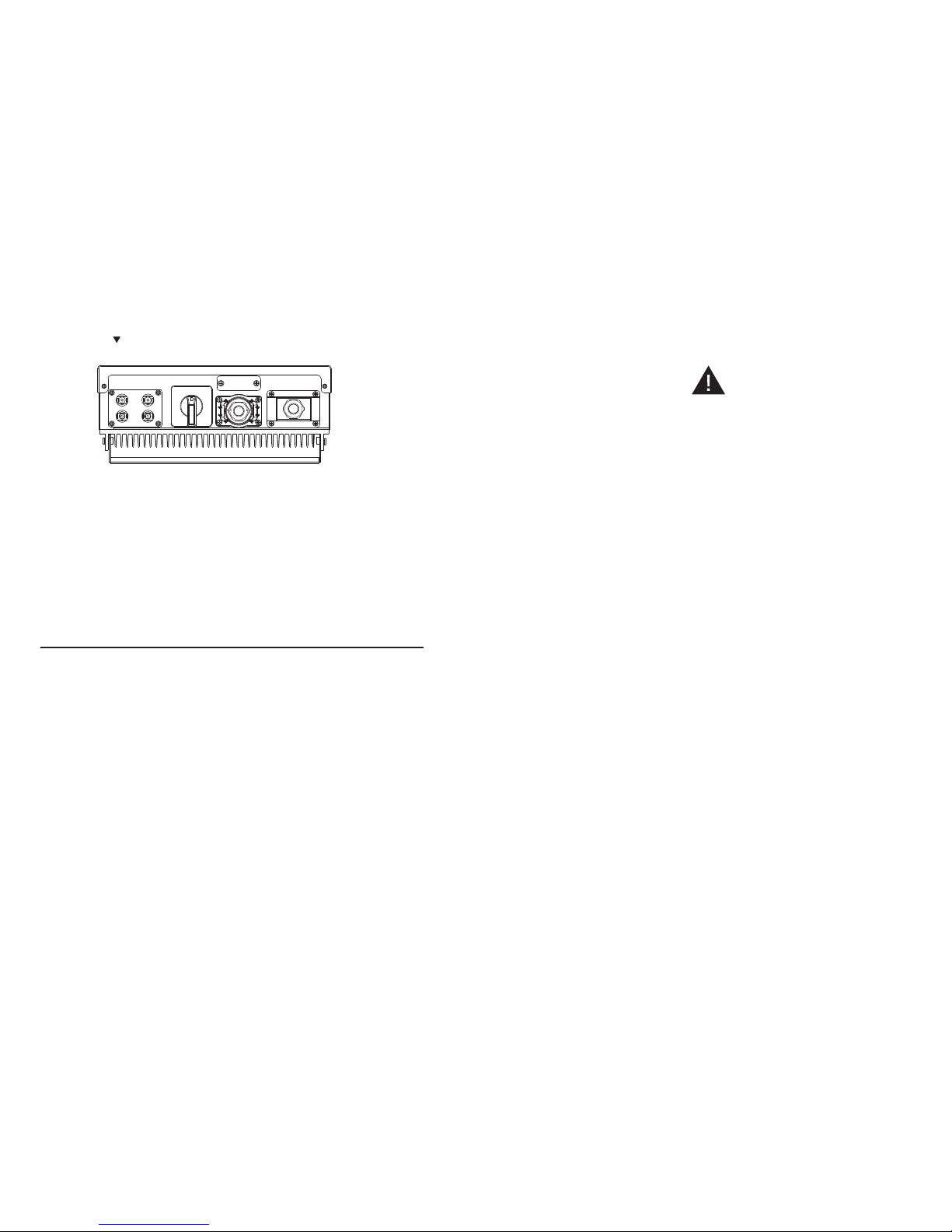
2.2 Fi xed on the wal l
Se le ct a w a l l o r s o l i d
vertical surface that can
support the PV-Inverter.
A
Inverter r eq ui re s a de qu at e
cooling spa ce . All ow at
least 20cm space abo ve
and below the inverter.
B
Using the mounting frame
as a template, drill 4 holes
as il l us tra t ed in im a ge
1+2.
C
Fix t he mounting fr am e as
the fig ure sho ws . Do not
make the scre ws to be
flush to the wal l. Instead,
leave 2 to 4mm exposed.
D
Hang th e in ve rt er o n the
mounting frame.
E
Chec k t h e in st a l l a tio n
conditions.
F
Do not install the PV-Inverter on a slanted surface.
Check the upper straps of PV-Inverter and ensure i t fi ts o n to t he b ra ck et .
Insert safety-lock scre ws t o th e bo tt om l eg t o se cu re t he i nv er te r (i ma ge 3 ).
Check th e secu re moun ti ng of th e PV-In ve rt er by tr yi ng to raise it from th e
bottom. The PV-Inverter should rem ai n fi rm ly a tt ac he d.
Select the installation location so that the status display can be easily viewed.
Choose a st ro ng mounting wal l to p re ve nt vibrations whi le i nv er te r is
operating
4
5
2.3 Co nnect to the g rid (AC util ity)
A
B
C
Measure th e grid (u ti li ty ) v ol ta ge and fr eq ue nc y. It should b e 2 30 VAC ( or
220VAC), 50/60Hz and single phase.
Open the brea ke r or f us e be tw ee n PV I nv er te r an d ut il it y.
For Inverter, AC w ires specifications as follows:
Model
_( m m)
Area(mm²)
AWG n o.
Gro wa tt 1 00 0
Sungold 1000
2.05
2.05
3.332
3.332
12
12
Page 5

E
A
B
C
under a ny condition! Ma ke sure th e m ax im um open circ ui t vo lt ag e ( Voc )
of ea ch PV st ri ng is les s tha n 450 V DC fo r Gro wa tt 10 00 ,S un gl od
1000,The length of input wire m us t be l es s th an 30 m.
Use H4 or M C4 (Mul ti -c on ta ct ) co nn ec to rs for PV a rr ay term in al s. Make
sure DC s wi tc h is o ff b ef ore connecting.
Connect the po si ti ve ne ga ti ve te rm in al s f ro m t he PV pa ne l t o p os it iv e (+)
terminals a nd ne ga ti ve (- ) terminals o n t he PV- In ve rt er. Ea ch DC te rm in al
on Inverter can withstand 20ADC.
Before c on ne ct in g P V p an el s t o D C t er mi na ls , p le as e make sure the
polarity is cor re ct . I nc or rec t pol ar it y con ne ct io n cou ld pe rm an en tl y
damage th e un it . Ch ec ks short-circu it current o f th e PV stri ng . The t ot al
short-circu it cu rre nt of the PV stri ng sho ul d be less than the inve rt er ’s
maximum DC curren t.
High volt ag es exis t when the PV p an el is ex po se d to t he sun .To re du ce
risk of electric sho ck , avoid tou ch in g live co mp on en ts a nd tr ea t
connection terminals care fu ll y.
D
2.4 Co nnect to PV pa nel (DC inpu t)
2.5 Ch ecking
6 7
2.5. 1 Country se lecting
When the PV pan el s ar e connected and th ei r outp ut volt ag e is g re at er than 70V dc
but t he AC g ri d is not ye t connected, inverter wi ll star t up auto ma ti ca ll y. I f it is t he
first ti me t o po we r o n th e in ve rt er after in st al la ti on , yo u may n ee d to s el ec t a s pe ci fi c
country* .Ot he rw is e, the int er fa ce will sta y at the ‘Ple as e Sele ct ’ inte rf ac e all the
time. There a re e le ve n op ti on s to s el ec t, a s th e li st b el ow.
Country/Regulation Name
options
VDE0126-1-1
Germany
UK_G83
Italy
France
Denmark
Belgium
Spain
Gre ec e
Turk ey
Hungary
// 0
// 1
// 2
// 3
// 4
// 5
// 6
// 7
// 8
// 9
// 1 0
Note: 1.If the country you want to select is not in the above list, please dire ct ly s el ec t
VDE0126-1-1.
2.The in ve rt er ca n o nl y b e u se d for s in gl e g ri d- co nn ec te d i n t he are a w he re CE I 0-21
and VDE-AR-N4105 are re qu es te d to a cc ord.
Please finish the country selecting accordi ng t o th e fo ll ow in g st ep s:
The LCD will qu ic kl y swit ch to and st ay at the ‘Pl ea se se le ct ’ inte rf ac e
after power on, as Fig 2-5-1.
A
Single knoc k on the LCD, coun tr ie s will vary from one to a no th er alon g
the abov e list ord er. Fig 2-5-2 act s as an exa mp le , and Ger ma ny is the
second selection.
B
Fig 2-5-1
Fig 2-5-2
*
If you h ave o rdere d the inve rter with spec ific count ry se tting s, th e par amete rs ha ve b een p reset in f actor y
and y ou don' t need to o perat e this st ep any mo re.
Page 6

When y ou need t o s el ec t an y o f these c ou nt ri es , y ou c an Do ub le knock to
enter the next interface. Here we s el ec t It al y as a n ex am pl e, a s Fi g 2- 5- 3.
C
Fig 2-5-3
When th e c ou nt ry ar ri ve s at It al y, Double k no ck to en te r th e t wo op ti on s
‘YES’ and ‘NO’, and the cursor stays at ‘NO’ in default, as Fig 2-5-4.
D
Fig 2-5-4
E
Fig 2-5-5
Single knock to select ‘YES’, as Fig 2-5-5.
F
Double k no ck to co nf ir m y ou r selection, LC D w il l d is pl ay ‘S el ec t OK’ w it h
the country name in the below, as Fig 2-5-6.
Note: if yo u s ti ll single k no ck at th e interface a s F ig 2- 5- 5, th e cursor wi ll
go to ‘NO’ agai n as Fig 2- 5- 4, then if you double kn oc k, the di sp la y wi ll
switch to the interface as Fig 2-5-3.
Fig 2-5-6
G
Note: If you have sel ec te d and c on fi rm ed an unwanted cou nt ry
neglectful, pl ea se c on ta ct G ro wa tt f or specific s of tw are to c le ar a nd res et
again.
When the selection is successful, the inverter will reb oo t au to ma ti ca ll y.
2.5. 2 Commissi oning
After th e inve rt er reboot, LCD will prod uc e the foll ow in g mess ag es in or de r:
‘Ser NO : xxx ’- >’ xx xx x’ -> ’F W ve rs io n’ -> ’Wa it in g’ -> ’N o AC co nn ec ti on ’, the
display rep ea ts ’ NO U ti li ty ’ an d LE D wi ll b e re d.
Close the AC br ea ke r or fu se between PV-In ve rt er and gri d. Turn on the DC
switch. The normal operating sequence begins.
Under n or ma l op er at in g co nd it io ns the LC D di sp la ys ‘Pow er : xx x. x W’ . Th at is
the power fed to the grid. The LED tur ns g reen.
This completes the check.
2.6 Sy stem diagr am
A
B
PV Panel: Pro vi de D C po we r to i nv er te r.
Converts DC (D ir ec t C ur re nt ) p ow er fr om PV panel ( s) to AC (A lt er na ti ng
Curre nt ) p ow er. B ec au se I nv er te r i s grid-connected it co nt rol s t he curre nt
amplitude accordi ng t o th e PV P anel power supply. Inv er te r al wa ys t ri es t o
convert the maximum power fro m yo ur P V pa ne l( s) .
98
Page 7

C
Connection s ys te m : Th is “i nt er fa ce ” be tw ee n Ut il it y a nd P V-I nv er te r ma y
consist of elec tr ic al bre ak er, fus e and con ne ct in g ter mi na ls . To c om pl y
with loca l sa fe ty stan da rd s an d co de s, the connection syst em shou ld be
designed and implemented by a qualified technician.
Utility: Referred t o as “ grid” in t hi s ma nu al , is t he w ay y ou r el ec tr ic p ow er
company pr ov id es p ow er to yo ur p la ce . P le as e n ot e th at In ve rt er can on ly
connect to low-voltage sysytems (namely,22 0_ 23 0VA C, 5 0/ 60 Hz ).
D
There are 3 diffe re nt m od es o f op er at io n.
3 Modes of Operation
3.1No rmal mode
In t hi s mo de , In ve rt er wo rk s no rm al ly. W he ne ve r th e su pp li ed po we r fr om P V pa ne l i s
suffi ci en t ( vo lt ag e> 90 VD C) , Inverter co nv er ts po we r t o the g ri d a s g en er at ed by th e
PV pan el . If the powe r is insu ff ic ie nt , (vol ta ge <7 0D C) Inverter ent er s a “w ai ti ng ”
state. Wh il st “wai ti ng ” Inverter us es just enou gh po we r fr om the P V pa ne l monitor
intern al s ys te m st at us . In n or ma l mo de t he L ED i s green.
3.2 Fa ult mode
The intern al int el li ge nt con tr ol le r can cont in uo us ly mon it or and adj us t the system
status. I f Inverter fi nd s any u ne xp ec te d conditions su ch as gr id probl em s or in te rnal
failure , it w il l di sp la y th e in fo rm at io n on i ts L CD a nd t he L ED w il l be r ed .
3.3 Sh utdown mod e
During peri od s of little or no sunlight, In ve rt er auto ma ti ca ll y stops ru nn in g. In this
mode, I nv er te r d oe s not t ak e a ny power f ro m t he gr id . Th e d is pl ay and L ED ’s on the
fro nt p an el d o no t wo rk .
Notes
Operating inv er te r is qu it e ea sy. Du ri ng normal ope ra ti on , In ve rt er ru ns
automatically with DC s wi tc h o n. Ho we ve r, to ac hi ev e maximum conversion
eff ic ie nc y of I nv er te r pl ea se r ea d th e fo ll ow in g in fo rm at io n:
a Auto matic ON-O FF:
Wi th DC swi tc h on, Inv er te r star ts up automatically when DC-power from the PV
panel is suff ic ie nt .
Once the PV - Inverter starts it enters one of the following 3 states:
1.Standby: T he PV st ri ng can onl y pr ov id e ju st eno ug h voltage t o minimum
req ui re me nt s of t he c on troller.
2.Wai ti ng : Whe n the PV str in g DC vol ta ge i s greater th an 70 V, Inve rt er en te rs a
“waiting” state and attempts to connect to the grid.
3.Normal operation: Wh en PV st ri ng DC voltage is greater t ha n 90V, In ve rt er
operates in the normal state.
11
10
Page 8

12
13
b Star ting-up di splay sequ ence:
Once the PV power is suffi ci en t, Inve rt er disp la ys information as shown in the flow
chart as follow:
SerNo: xxxxxxxx Module: xxxxxxxxx FW Version: x.x.x
Connect in xxS Connect OK Power: xxxx.xW
LCD ba cklight co ntrol:
To save power, the L CD d is pl ay ’s bac kl ig ht a ut om at ic al ly t ur ns o ff a ft er 3 0 se co nd s.
The First line of LCD
STATE
DISPLAY
REMARK
Wai t St at e
Inverter State
Fault State
Auto Test State
Pro gr am S ta te
Standby
Wai ti ng
Connect in xxS
Reconnect in xxS
Connect OK
Power: xxxx.xW
Error : xx x
Auto Testing
Pro gr am mi ng
PV voltage low
Initial waiting
System checking
System checking
Connect to Grid
Inverter watt at working
System Fault
Pro te ct in g au to t es t
Update Software
The second line of LCD
SerNo CYCLE DISPLAY DISPLAY TI ME /S
REMARK
1
2
3
4
5
6
7
8
9
10
11
12
13
Etoday: xx.x KWh
Eall: xxx.x KWh
Tall: xx.x h
PV: xx x/ xx x. B : xx x
AC: xxxV F: xx.xHz
SerNo: xxxxxxxxxx
Module: PX UX MX SX
FW version: x.x.x
Enable Auto Test
Set Language
Set LCD Contrast
System F: XXHz
COM addre ss : xx
4
4
4
4
4
4
4
4
4
4
4
4
4
The energy today
The total energy
The total work time
The PV1 & PV2 voltage
The AC voltage and freq ue nc y
The serial number
The inverter module
The software ve rs io n
The enable auto test
Set LCD language
Set LCD contrast
The grid freq ue nc y
The communication Addre ss
3.4 So und contro l LCD displa y
The display on th e i nv er te r c an be co nt rol b y K no ck on th e f ront of it . S ou nd co nt rol
can define the display language, luminance of the display, aut o- te st a nd f requency.
When t he L CD i s dark:
Knock and double knock make it becomes bright.
Knock to make it display next information or change the set situation.
Double knock make the display stand for 30 second on 1-5. And enter set menu on
6-12.
When t he L CD i s brigh t:
Page 9

14 15
Set th e di sp lay:
Set language
Knock to make th e display brig ht -> kn oc k to “s et language” -> do ub le knock to
enter “ la ng ua ge : En gl is h” -> k no ck to s el ec t th e la ng ua ge you ne ed and wa it unti l
the display become dark.
Set luminance of the display
Knock to ma ke th e d is pl ay bright -> k no ck to “s et LC D c on tr as t” -> d ou bl e k no ck to
enter “L CD c on tr as t 2” -> knock to s el ec t the l um in an ce y ou need a nd w ai t until t he
display become dark.
Auto test
Knock to make th e di sp la y br ig ht - > kn oc k to “ En ab le A uto test” -> do ub le k no ck t o
enter “Wa it in g to s ta rt ” -> k no ck t o st ar t au to t es t an d wa it f or t he t es t result.
Fre qu en cy
Knock to m ak e th e di sp la y br ig ht - > knock t o “S ys te m F: x xH z” -> d ou bl e kn oc k to
enter “System F: x xH z” - > knock t o se le ct t he F re qu en cy y ou n ee d an d wait un ti l th e
display become dark.
Set contrast
Knock to m ak e th e di sp la y bright -> kn oc k to “ CO M Ad dr es s: x x” -> d ou bl e kn oc k
to change the Addre ss m od e -> k no ck t o se t ad dr es s.
Inverter Status 4
Inverter is des ig ne d to be user-friendly; ther ef ore, the st at us of the Inverter can be
easily und er st oo d by reading the in fo rm at io n sho wn on the fron t pan el display. All
possible messages are s ho wn i n th e fo ll ow in g ta bl e.
DISPLAY
OPERATIO N
Auto Test Failed
No AC Connection
PV Isolation Low
Residual I High
Output High DCI
PV Voltage High
AC V Outrange
AC F Outrange
System fault
Auto test do not pass
No utility, no g ri d co nn ec t
Insulation prob le m
GFCI fault
Output Curren t DC o ff se t to o hi gh
PV panel voltage too high
Grid voltage out of range
Grid freq ue nc y ou t of r an ge
Inverter fault
Error : 10 0
Error : 10 1
Error : 10 2
Error : 11 6
Error : 11 7
Error : 11 8
Error : 11 9
Error : 12 0
Error : 12 1
Error : 12 2
2.5V Refere nc e Vol ta ge F au lt
Communication Fault
Consistent Fault
EEPROM Fault
Relay Fault
Init Model Fault
GFCI Device Damage
HCT Fault
Communication Fault
Bus Voltage Fault
Set Queensland grid voltage range
Knock t o m ak e t he di sp la y become br ig ht -> Kn oc k t o item “M od el : G TX XX XX X” ->
Double kno ck to enter “No rm al Volt ra ng e” -> Knock to chan ge it to “Qld Vm ax
255v” -> wait until the display become dark, then the inverter saved change.
Note: this function is only for Ergon Energy area , Qu ee ns la nd , Au st ra li a.
Page 10

16
5 Communication
5.1 Co mmunicat ions softw are instru ctions
ShineNET is a PC soft wa re th at co mm un ic at es wi th Sh in e Inv er te r to ana ly ze th e
inverter work state. It is co nv en ie nt for yo u to know the in ve rt er real time work in g
state and the history work information.
Spec:
1. Communicate with inverter by RS232 and Bluetooth.
2. Construct net with in ve rt er, GROmonitor and ShineNet by RS 23 2, Bl ue to ot h
and Intern et .
3. Two In te rf ac es : Mu lt i In ve rt er I nt er fa ce a nd Wa ve D at a In te rf ac e.
4. In Mu lt i Inverter In te rf ac e: 9 in ve rt er s w or ki ng data at the s am e ti me , y ou can
select your own compare i nv er te rs a nd p ar am et er s.
5. In Wave Da ta Inte rf ac e: Query the in ve rt er real time and history po we r wa ve ,
work data and error i nf or ma ti on .
6. Multi languages: Eng li sh , Simp le Chi ne se , Fren ch , Germ an , Span is h and etc .
Support OS: Wi nX P / Vi st a / wi n7 / 2 00 0/ 2 00 3
5.2 Mo nitor
After se tt in g the soft wa re the use r can moni to r the inverter. The righ t side of the
main interface is the detailed information of inverter.
5.3 De tailed inf ormation
Detailed setting method and other functions ref er t o “S hi ne NE T Ma nu al .” i n th e CD .
5.4 RS 4 85 cable con nection
1. P le as e ta ke o ut the RS 48 5 wa te rp ro of d ev ic e fr om t he Accessories ba g, e ve n if you
don’t cho os e RS485 as comm un ic at io n meth od , the RS48 5 waterpro of dev ic e still
has to be locked on the inverter.
2. Twis t o ff th e w at er proof connector, a nd pu ll ou t o ne or two St op pe r a cc ording to
your demand.
17
Page 11

3. Mak e the cabl e thro ug h the hol e of ru bb er st op pe r and the RS485 wat er proof
cover. The t yp e of c ab le i s recommended as “KVVRP22/2*1.5”.
4. Take out the RS485 connection terminal.
1
2
3
5. Con ne ct th e cab le to th e RS4 85 te rm in al (‘ 1’ to ‘1 ’, ‘3 ’ to ‘3’ , and ‘2’ to the
shielding ne t) → plu g RS 48 5 terminals i nt o th e inverter → tight wa te rp roof
connector →lock waterpro of d ev ic e on to t he i nv er te r.
Note:
① As to the connection between inverters, please re fe r to t he f ol lo wi ng f ig ur e.
1
2 3
RS4 85 term inal of t he inve rter
Com p ort of
Shi ne WebB ox
RS 48 5 termi nal of th e inver ter 1
1
2 312 3
RS 48 5 termi nal of th e inver ter 2
1
2 312 3
② As to the connection between in ve rt er an d S hi ne WebBox (or Shine Pano), please
ref er t o th e fo ll ow in g fi gu re .
19
18
Page 12

21
6 Trouble Shooting
In most sit ua ti on s, the Inverter re qu ires very lit tl e serv ic e. However, if I nv er te r is no t
able to work per fe ct ly, ple as e refer to th e foll ow in g instructions befo re calling you r
local dealer.
Should any prob le ms ar is e, th e L ED on th e f ro nt pa ne l w il l b e r ed an d t he LC D d is pl ay s
the r el ev an t in fo rm at io n. Plea se refer to t he foll ow in g fo r a list of pote nt ia l pr ob le ms
and their solutions.
SYSTEM FAULT
Ground I Fault
Isolation Fault
Grid Fault
1. The grou nd c ur re nt i s to o hi gh .
2. Unplug the inputs from t he P V ge ne ra to r an d ch ec k th e pe ri ph er al A C sy st em .
3. After the cause is cleared , re -p lu g th e PV p an el a nd c he ck P V-I nv er te r st at us .
4. If the pro bl em p er si st s pl ea se c al l se rv ic e.
1. Check the impedance is between PV (+) & PV (-) and the PV-Inverter is earthed.
The impedance must be gre at er t ha n 8M .
2. If the pro bl em p er si st s pl ea se c al l se rv ic e.
1. Wa it f or 5 m in ut es , if t he g ri d return s to n or ma l, P V-I nv er te r au to ma ti ca ll y restarts.
2. Make sure gr id v ol ta ge a nd f re qu en cy m ee t th e sp ec if ic at io ns .
3. If the pro bl em p er si st s pl ea se c al l se rv ic e.
4. Check grid usability.
No AC connection
1. Grid is not connected.
2. Check grid connection cables.
INVERTER FAILURE
PV Over Voltage
Consistent Fault
1. Che ck the o pe n P V v ol ta ge ; see if it i s g re at er than or t oo cl os e t o 4 50 VD C.
2. If PV voltage is less than 450VDC, and the pro bl em s ti ll o cc ur s, p le as e ca ll l oc al s er vi ce .
1. Disconnect PV (+) or PV (-) from t he i np ut , re st ar t th e PV- In ve rt er.
2. If it does not work, call service.
If there is n o di sp la y on t he p an el , pl ea se c he ck P V-input connections. If the voltage is
higher than 90V, call y ou r lo ca l se rv ic e.
During p er io ds of li tt le or no sunlight, the P V-I nv er te r m ay co nt in uo us ly st ar t u p and
shut d ow n. Thi s i s d ue to i ns ufficient po we r g en er at ed to o pe ra te the con tr ol
circu it s.
Specifications
7
Inp ut Data
Max. i nput cu rrent
/per s tring
Max. D C volta ge
Max. D C power
PV vol tage ra nge
MPP vo ltage r ange
Numb er of MPP t racke rs/
stri ngs per M PP trac ker
Gro watt1 000
10A/ 10A
1300 W
450V
70V-4 50V
110V- 400V
1 / 1
Out put Dat a
AC con necti on
Eff icien cy
MPPT e ffici ency
Nomi nal AC ou tput po wer
Max. A C power
Max. o utput c urren t
AC nom inal vo ltage ; range
AC gri d frequ ency ; ra nge
Phas e shift ( cos φ)
THDI
Max . ef ficie ncy
Euro -eta
99.5 %
97%
95.5 %
Pro tecti on Devi ces
Inte grate d all-p ole sen sitiv e
leak age cur rent mo nitor ing uni t
Gen eral Da ta
DC rev erse po larit y prote ction
AC sho rt-ci rcuit p rotec tion
Grou nd faul t monit oring
Grid m onito ring
Dime nsion s (W / H / D) in mm
Weig ht
yes
yes
yes
yes
yes
360/ 329/1 32
11.5 K G
Oper ating t emper ature r ange
–25° C..+6 0°C
Cont inuou s full ou tput po wer
temp eratu re rang e
–25° C..+5 0°C
Nois e emiss ion (ty pical ) ≤25 dB( A)
Sing le phas e
1000 W
1100 W
5.5A
220, 230,2 40V;
180Va c-280 Vac
50Hz ,60Hz ;±5Hz
1
< 3%
Cons umpti on: ope ratin g
(sta ndby) / n ight
Topolo gy
<5W /< 0 .5 W
tran sform erles s
Cool ing con cept
No fan
Inst allat ion: In door/
Outd oors (I P65 ele ctron ics)
yes / ye s
VDE 0126-1-1,N4105,
IEC 62109,G83,CE,
ENEL Guideline(CEI 0-21+A70)
Cer tific ates an d Appro vals
20
Sun gold 10 00
10A/ 10A
1300 W
450V
70V-4 50V
110V- 450V
1 / 1
Sing le phas e
1000 W
1100 W
5.5A
230V;
207Va c~263 Vac
50Hz ,60Hz ;±5Hz
1
< 3%
99.5 %
97%
95.5 %
yes
yes
yes
yes
yes
360/ 329/1 32
11.5 K G
–25° C..+6 0°C
–25° C..+5 0°C
≤ 25 dB( A)
<5W /< 0 .5 W
tran sform erles s
No fan
yes / ye s
AS 477 7, AS/N ZS 3100
 Loading...