

Page 1

ARK High Voltage Battery System
Download
Manual
Shenzhen Growatt New Energy Co., Ltd
4-13/F,Building A,Sino-German(Europe) Industrial Park,
Hangcheng Ave, Bao'an District, Shenzhen, China
T
+86 755 2747 1942
service@ginverter.com
E
www.ginverter.com
W
GR-UM-223-A-02
Growatt New Energy
User Manual(A1)
Page 2
About this Document
Symbol
Description
Indicates a potentially hazardous situation, if not avoided, could re su lt
in serious injury or death.
This document describes the installation, electrical connection, operation, commission,
maintenance and troubleshooting of ARK High Voltage Battery System. Before i ns ta ll in g
and operating ARK High Voltage Battery System, ensure that you are f am il ia r wi th
product feature s, f un ct io ns , an d sa fe ty p recautions provided in this document.
1 Product Overview
Contents
1.1 Intended Use
1.2 Appearance
1.3 Working Principle and Function
WARNING
2 Safety
3 Storage and Transportation
4 Installation
5 Power on/off Battery system
6 Maintenance Guide
2.1 Basic security
2.2 Safety Precautions
2.3 War ning Labels
2.4 Emergency Responses
3.1 Storage Requirements
3.2 Tran sp or ta ti on R eq ui rement
4.1 Basic Installation Requirements
4.2 Installation Required Tools
4.3 Installation Procedures
4.4 Electrical Connection
5.1 Power on Battery system
5.2 Power off battery system
6.1 Preparation
6.2 Battery pack or high voltage
controller re pl ac em en t
6.3 System fault information and
suggestions
7 Technical Specifications
Appendix I
Appendix II
7.1 System Data
7.2 Battery System designation
7.3 HVC 60050-A1
7.4 ARK 2.5H-A1
Page 3

1 Product Overview
Location
Port
Function
1
PCS
Communication with PCS
2
Link-In
Battery system parallel communication entrance
3
Pressure relief valve
Pressures i ns id e is released via the vent
4
Link-Out
Battery system parallel communication export
5
BMU
Communication with battery module
6
Module+/ Module-
Connect to the power terminal of the battery string
7
Ground terminal
8
PCS+/PCS-
The output from battery system to the PCS
9
Ground terminal
10
USB interface
USB communication interface
11
LED
SOC and working status indication of the system
12
Breaker
Breaker to turn on/off the whole battery system
13
Power button
Wak e up t he b at te ry s ys te m
Location
Port
Function
1
Link0
Communicate with the previous module Link1
2
Link1
Communicate with the next module Link0
3
Module-
Connect to the positive terminal of the adjacent
module
4
Module+
Connect to the negative terminal of the adjacent
module
5
Ground terminal
6
Pressure relief valve
Pressures i ns id e is released via the vent
7
Ground terminal
1.1 Intended Use
The entire ARK Hig h Voltage Ba tt er y System in cl ud es a HVC 60050-A1(high voltage
controller) and multiple ARK 2.5H-A1 (battery pack).
Each ARK 2.5H-A1 consists of 50A h c el ls wh ic h form 51.2V voltage battery pack via one
parallel and s ix te en s er ia l co nn ec ti on (1P16 S) . Two to ten ARK 2. 5H -A 1 ca n be connected
in serial to extend the capacity and power of energy storage system.
The ARK battery system powers the loads th rough PCS at nighttime without solar; when
solar b ec om es available du ri ng daytime, solar energy powers t he loads as a priority and
store res id ua l so la r po we r in to t he A RK b at te ry s ys te m.
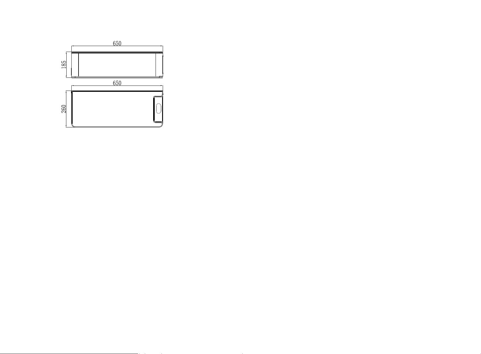
1.2 Appearance
1.2.1 HVC 60050-A1 (high voltage controller)
The high voltage control le r is com po se d of bat te ry co ntrol unit, DC brea ke r, power
supply and communication terminals. The appearance of the product is shown as below.
Dimension (unit: mm)
1.2.2 ARK 2.5H-A1 (battery pack)
ARK 2.5H-A1 consists of battery module (including cell and mechanical parts), Battery
management unit (BMU) as well as power and communication terminals. Product
appearance is shown as below.
Fig 1.1: Schematic diagram of power panel
Fig 1.2: Dimension of HVC 60050-A1
Fig 1.3: Schematic diagram of power panel
1
2
Page 4
Dimension (unit: mm)
Fig 1.4: Dimension of ARK 2.5H-A1
1.3 Working Principle and Function
The ARK high voltage battery system is composed of a high voltage controller HVC
60050-A1 and battery pack ARK 2.5H-A1 in series. It contains electrochemical batteries,
battery control units, battery management units, power and signal terminals, and
mechanical parts.
Compared with other battery systems, it has better charging and discharging
performance, higher charging and discharging efficiency, more accurate status monitor,
longer cycle life and less self-discharge loss.
A single cluster system can connect 2 to 10 packs in series to increase the capacity and
power of the battery system. The entire battery system communicates with the inverter
through CAN communication, and the operation stability is high.
Ø Monitoring: voltage, current and temperature de te ct io n of b ot h si ng le c el ls a nd
battery system.
Ø Protection and Alarm: pro te ct io n an d al ar m wh en o ve rv ol ta ge , un de r vo lt ag e, o ve r
current, over temperature o r un de r te mp er at ure occurs. See Appendix I for the details.
Ø Report: report all alarm and status data to PCS.
Ø Series connection: support two to ten packs in Series connection.
Ø Power failure triggered b y fa ul t: 1 0 mi nu te s af te r th e ba tt er y sy st em a nd P CS
communication is disconnected or 15 minutes after undervoltage protection.
Safety 2
When installing or using a b at te ry s ys te m, t he s af et y inform at io n contained in this
section m us t always be followed. Fo r safety reasons, it is the installer's responsibility to
be familiar with this manual and all war ni ng s be fo re installation.
2.1 Basic security
The battery system has been designed and tested in accordance with strict rules with
intern at io na l sa fe ty c er ti fi ca ti on requirements. Before a ny i ns ta ll at io n or u se o f th e
battery system, please read all safety instructions caref ul ly a nd a lw ay s fo ll ow t he relevant
rules. Growatt is not res po ns ib le f or a ny c on se qu en ce s resulting from violation of the
following regulations:
Ÿ Damage occurred during transportation.
Ÿ Incorrect transportation, storage, installation and use, or customer fails to convey the
correct information about transportation, storage, installation and use to terminal.
customers.
Ÿ Non-professional installation.
Ÿ Failure to obey the rules of this operation instructions and safety pre ca ut io ns i n th is
document.
Ÿ Unauthorized modifications or removal of the software p ac ka ge .
Ÿ The product's tamper label is damaged or the prod uc t la ck s an y pa rt s (e xc ep t
authorized disassembly parts).
Ÿ Operation in extreme enviro nm en ts w hi ch a re not allowed in this document .
Ÿ Repair, di sa ss em bl e, o r ch an ge p ac ks w it ho ut a ut ho ri za ti on a nd c au se f ai lu re.
Ÿ Damage to shell labels or modifies date of production.
Ÿ Packs fail to be charge for more than six months.
Ÿ Damages due to force majeure (s uc h as l ig ht ni ng , ea rt hq ua ke s, f ire, and storms).
Ÿ War ra nt y ex pi ra ti on .
2.2 Safety Precautions
2.2.1 Environment req ui rements
Ø Do not expose the battery to temperature above 50℃ or heat sourc es .
Ø Do not install or use the battery in wet locations, moisture, corro si ve g as es o r li qu id s,
such as bathroom.
Ø Do not expose the battery to direct sunlight for extended periods of time.
Ø Place battery in safe place away from childre n an d an im al s.
Ø Battery power terminals shall not touch conductive objects such as wires.
Ø Do not dispose the batteries in fire, which may cause an explosion.
Ø The battery system shall not come in contact with liquids.
3
4
Page 5

2.2.2 Operation Precautions
Symbols
Description
Do not dispose in trash
Lithium ion battery can be recycled
Certification in European union are a
Electric shock hazard
Explosive gas
May leak corrosive electrol yt e
Heavy enough to cause severe injury
Keep the Pack away from childre n
Make sure the battery polarity well connected
Do not expose to fire
Operate as the Manual
The performance will be limited
when the temperature is below
0°C.
Ø Do not touch the battery system with wet hands.
Ø Do not disassemble the battery system without permission.
Ø Do not crush, drop or pierc e th e ba tt er y pa ck a nd h ig h vo lt ag e co nt roller.
Ø Dispose the batteries according to local safety reg ul at io ns .
Ø Store and rec ha rg e ba tt er y in a cc ordance with this manual.
Ø Ensure the connection of grou nd w ire reliable.
Ø Remove all metal objects such as watches and rings that could cause a short-circuit
before installation, re pl ac em en t an d ma in te na nc e.
Ø The pack shall be repaire d, replaced or maintained by skilled personal that has been
recognized.
Ø When storing or handling batteries ,do not stack batteries without package.
Ø Do not broke the battery, the released electrol yt e ma y be t ox ic a nd i s ha rm fu l to s ki n
and eyes.
Ø Packaged batteries should not be stacked more than specified number stipulated on
the packing case.
Ø Do not use damaged, failed or deformed batteries, which may lead to high
temperature or even dangero us a cc id en ts . Co nt in ue d op er at io n of d am ag ed b at te ry m ay
result in electrical shock, fire or e ve n wo rs e.
2.3 Warning Labels
Model
Nomin al/ Rated C apa ci ty
Nomin al/ Rated E ner gy
Rated C urr ent
Opera tin g Amb ien t
Temp eratu re
Fig 2.1: Nameplate
ARK H igh Volt age Bat tery Sy stem
ARK 5 .1H-A 1/102 .4V/
5.1 2kWh/ 4.6kW h
ARK 7 .6H-A 1/153 .6V/
7.6 8kWh/ 6.9kW h
ARK 1 0.2H- A1/20 4.8V/
10. 24kWh /9.2k Wh
ARK 1 2.8H- A1/25 6.0V/
Sys tem Mod el/
Nom inal Vol tage/
Nom inal En ergy/
Rat ed Ener gy
Hig h Voltag e
Con troll er Mode l
Pro tecti ve Clas s
Rat ed Curr ent
Nom inal/ Rated
Cap acity
Ing ress
Pro tecti on
Ope ratin gAmbi ent
Tempe ratur e
12. 80kWh /11.5k Wh
ARK 1 5.3H- A1/30 7.2V/
15. 36kWh /13.8 kWh
ARK 1 7.9H- A1/35 8.4V/
17. 92kWh /16.1 kWh
ARK 2 0.4H- A1/40 9.6V/
20. 48kWh /18.4 kWh
ARK 2 3.0H- A1/46 0.8V/
23. 04kWh /20.7 kWh
ARK 2 5.6H- A1/51 2.0V/
25. 6kWh/ 23.04 kWh
HVC 6 0050- A1
50A h/45A h
-10 °C ~ +50° C
ARK 2.5 H- A1
51.2V
50Ah/ 45 Ah
256 0Wh/230 0Wh
25A
-10°C ~ + 50 °C
Made In China
I
25A
IP6 5
WARNING
Do no t disas sembl e or alte r the PACK to a void he at ,exp losio n or fire .
Do no t use the PAC K beyon d speci fide co nditi ons.I t might c ause he at
gen erati on,da mage, or dete riora tion of i ts perf orman ce.
Do no t throw, drop, hit,d rive a na il in,s tamp on t he PACK.I t may cau se
hea t gener ation ,expl osion ,or fir e.
In ca se of ele ctrol yte lea kage, keep le aked el ectro lyte aw ay from
con tact wi th eyes o r skin. immed iatel y clean w ith wat er and se ek help
fro m a docto r.
Do no t put the PAC K into a fi re.Do n ot use it o r leave i t on a plac e
nea r fire, heate rs,or h igh tem perat ure sou rces. It may ca use ove r
tem perat ure,e xplos ion or fi re.
Do no t subme rge the PAC K in wate r,or wet t he prod uct.I t may cau se
hea t gener ation ,expl osion , or fire .
Do no t rever sely co nnect t he PACK pos itive (+)an d negat ive(- )term inal.
Do no t short c ircui t by lett ing the PAC K termi nals( +and -) conta ct a wire
or an y metal .
The u nit is he avy eno ugh to ca use sev ere inj ury.
Kee p out of re ach of ch ildre n or anim als.
X
Fig 2.2: Label
5
X
Fig 2.3: Nameplate
Made In China
Notice
6
Page 6

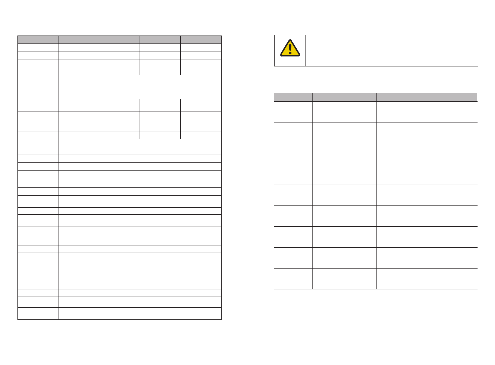
2.4 Emergency Responses
Situation Occurs
Description and action need
Leakage
Avoid touch of leaking liquid or gas. If you touch the leaking
electrolyte, do as below immediately.
Inhalation: Evacuate the contaminated area, and seek medical help.
Eye contact: Rinse eyes with flowing water for 15 minutes, and seek
medical help.
Skin contact: Rinse contacted area thorou gh ly w it h so ap a nd w at er,
and seek medical help.
Ingestion: Vomiting, and seek medical help.
On fire
It's hard for battery system ignite spontaneously. If the battery has
caught a fire, do not try to extinguish the fire bu t ev ac ua te p eo pl e
immediately.
Wet Packs
If the battery system is soaked or submerged in water, do no t ac ce ss
it. Contact Growatt or distributors immediately for technical
assistance.
Damaged shell
Damage to the shell is very dangerous, so special attention must be
paid. They are no longer suitable for use and may be dangerou s to
personnel. If the battery case is damaged, please stop using it and
contact Growatt or a distributor.
If not follow the above instructions for long-term storage, the battery
cycle life will be reduced or even damaged.
Manufacturer takes fore se ea bl e ri sk s ce na ri os i nt o co ns id er at io n an d is d es ig ne d to
reduce hazard s an d da ng er s. H ow ev er, if the following situation occurs, do as below:
Storage and Transportation 3
3.1 Storage Requirements
Ø Place the product follow the identification on the packing case during storage.
Ø Do not put the product upside down or sidelong.
Ø The defective product needs to be separated fro m ot he r product.
Ø The storage environment req ui rements are as follows:
Ÿ Place the product in a dry, clean and well ventilated place.
Ÿ The storage temperature for a short week(7 days) is between -20°C to 50℃.
Ÿ If you store the prod uc t ov er a l on g pe ri od o f si x mo nt hs , th e st or ag e te mp er at ure is
between -20°C to 40°C, relative humidity: 5%~95%RH.
Ÿ Place the product away from c or rosive and organic substances (including gas
exposure).
Ÿ Free from d irect exposure to sunlight and rain.
Ÿ At least two meters away from heat source s (s uc h as a r ad ia to r) .
Ÿ Free from e xp os ure to intensive infrared radiation.
Ø If the battery is stored for more t ha n si x mo nt hs , th e ba tt er y pa ck s ha ll b e recharged to
40% SOC every six months using a charger.
Notice
3.2 Transportation Requirement
Battery pack has been certified in UN38.3 (Section 38.3 of the sixth Revised Edition of the
Recommendations on the Tra ns po rt o f Da ng erous Goods: Manual of Tests and Criteria)
and SN/T 0370.2-2009 (Part 2: Performance Test of the Rules for the Inspection of
Packaging for Exporting Dangerous Goods). Battery pack is classified as category 9
dangerous goods.
Ø The battery pack shall not be transported with other inflammable, explosive or toxic
substances.
Ø Ensure the original Package and label complete and re co gn iz ab le .
Ø Prohibit dire ct e xp os ure to sunlight, rain, condensing water caused by temperature
differe nc e an d me ch an ic al d am ag es .
Ø Prohibit to pile up more th an s ix b at te ry p ac k.
Ø There will be a dro p in c ap ac it y du ri ng t ra ns po rt at io n an d st or ag e.
Ø Tran sp or ta ti on t em pe ra tu re is between -20°C to 40°C, relative humidity: 5%~95%RH.
7
8
Page 7

4 Installation
Ø The installation and use of batteries involve a lot of expertise.
Therefore , pl ea se e ns ure that technicians have obtained relevant
technical certificates before operation.
Ø Ensure to rea d th e Gu id an ce b ef ore installation in order to understand
product information and safety cautions.
Ø Operators should be well trained technicians and fully understand the
whole photovoltaic system, grid network, battery system, working
principle and national regional standards .
Ø Installers must use insulating tools and wear safety equipment.
Ø Device damages caused by failure to comply with storage,
transportation, installation and use requirem en ts s pe ci fi ed i n Gu id an ce
are not coved by Warranty.
Ø Do not install or use battery near explosive or inflammable substances.
Ø Use battery in well-ventilated environment with temperature r an gi ng
from -10℃ to 50℃.
Ø Maintain a minimum level of dust and dirt in the environment.
Ø Do not install battery in highly humid area such as bathroo m.
Ø Please make sure that all battery pack connected in series are from the
same batch, the same model and the same manufacturer. Do not mix old
batteries with new batteries. A battery pack that does not exceed 300
cycles is defined as a new battery.
Ø Before installing in series, make sure th at t he v ol ta ge d ifference of the
battery pack must be less than or equal to 0.5V.
Ø When installing the batteries, we recommend that the manufacturing
date of batteries in the same system should be within 3 months. The
manufacturing date of batteries can be interpreted thro ug h ba r co de
(refer to Appendix 1).
Do not place the battery pack upside down.
WARNING
Notice
4.1 Installation environment
Ø The battery system can be installed indoors or outdoors. The following conditions are
allowed:
9
Fig 4.1:Acceptable wall mounted installation
Fig 4.2:Acceptable floor standing installation
WARNING
Ø When installing outdoors, it is necessary to install sunshades and rain shelters to avoid
direct exposure t o su nl ig ht a nd r ai n.
Fig 4.3: Sunshades and rain shelters
10
Page 8

4.2 Installation Required Tools
Ø The high voltage controller (HVC 60050-A1) and the battery pack (ARK
2.5H-A1) are standard a cc es so ri es , pl ea se b e su re to purchase both, a
battery system only needs a high voltage controller (HVC 60050-A1),
battery pack (ARK 2.5H-A1) You c an f reely match the number within 2 to
10 .
Ø The battery base is only used for floor installation, and the wall bracket
is only used for wall installation .The battery base and wall bracket are
optional accessory, no t st an da rd accessory.
Ø You ne ed t o se pa ra te ly p urchase the connection cable from the high
voltage controller (HVC 60050-A1) to the PCS.
Ø If you want to install the same battery system in two lines, you need to
purchase a extension cable separately for connection.
Ø The installation method can be selected wall Mounted installation or
floor standing installation as required .
The following tools are req ui red to install the battery system:
4.3.1.2 Check the list of ARK 2.5H-A1
Drill
Pencil
Screw Driver
Tap Measure
Wre nc h
Multimeter
It is recommended to wear the following safety gear when dealing with the battery
system.
Insulated Glove
Safety Goggle Safety Shoes
4.3 Installation Procedures
4.3.1 Pre-installation Check
Ø Check the PACK package before op en i t. I f an y ab no rm it y is d et ec te d, d o no t op en t he
Package and contact your distributor.
Ø Check the quantity of all parts inside according to the package list. If there is a ny p ar t
missing or damaged, please contact your distributor.
4.3.1.1 Check the list of HVC 60050-A1
Se ri al c a bl e X1
Fig 4.5:compoents and parts ARK 2.5H-A1
4.3.1.3 Check the battery base and wall bracket
Ba t t er y b as e
Fig 4.6:Optional installation accessories
Notice
Fig 4.4:compoents and parts of HVC 60050-A1
11
Pl u g X1
12
Page 9

4.3.2 Wall Mounted Installation
Ø The number of wall-mounted installations should not exceed 4
(including high voltage controllers).
Ø If there are mo re than 4, please install them in two lines, and the
spacing should be greater than or equal to 300mm.
Ø If more than 4 batteries are us ed , b as e mo un ti ng i s recommended.
Ø For floor installation with base , the maximum stack number of the
battery is ten. But if the battery number is greater than six , we
recommend stacking them in two lines.
Ø The safety part needs to be installed at the top battery, ho we ve r, once
the number of the battery pack is higher than 7, one more safety part
should be installed in the middle battery which is shown the last step.
Ø Do not forget wear ESD wrist strap and gloves, safety gloves and
goggles.
4.3.3 Floor Standing Installation
Fig 4.8: Floor standing installation process
Ø Step 1: Place the battery base in the area to be installed, and mark the position of the
installation hole with a marker. The m in im um d is ta nc e be tw ee n th e wa ll a nd t he b at te ry
is 300mm.
Ø Step 2: Select an alloy drill with a diameter of 10mm and drill a mounting hole at least
60mm deep in the wall. Insert the expansion pipe into the hole and screw in the screw s to
secure the anti rol l ov er p la te .
Ø Step 3: Stack the battery on the base, connect the fixed connecting strip between the
battery packs.
Ø Step 4: Make sure the battery will not shake, and then lock the safety scre w.
Ø Step 1: Please make sure that the weight capacity of the wall should exceed 150kg.
Ø Step 2: Put bracket on wall and mark drilling spots. Keep a minimum distance of
300mm between the wall and bracket; a minimum distance of 500mm between bracket
and ground.
Ø Step 3: Choose an alloy drill with a diameter of 8mm, and drill at least 60mm mounting
holes in the wall. Clean the soil and insert the expansion tube into the hole, then screw in
the screw to fix the wall mount.
Ø Step 4: Fix the battery on the wall mount, make sure that the battery will not shake,
and then lock the safety screw.
Notice
13
Notice
4.4 Electrical Connection
Notice
14
Page 10

4.4.1 Definition of RJ45 communication port pin
No.
PCS
LINK_IN
LINK_OUT
BMU
1
RS485_B
Add_in
Add_out
\
2
RS485_A
Master
GND\3
GND
GND
Slaver
IMA_isoSPI
4
CAN_H
GND
GND
IPA_isoSPI
5
CAN_L
CANH
CANH
IMB_isoSPI
6
GND
CANL
CANL
IPB_isoSPI
7
WAK E-
GND
GND\8
WAK E+
Power_ON
Power_ON
\
No.
LINK 0
LINK 1
1
\
\
2
\
\
3
\
\4\
\
5
IMA_isoSPI
IMB_isoSPI
6
IPA_isoSPI
IPB_isoSPI
7
\
\8\
\
Ø When connecting the power line, it must be the same color terminal to
connect , otherwise there may be dangers such as short circ ui t .
Ø A DC circuit brea ke r ha s be en i ns ta ll ed i n th e hi gh v ol ta ge c on troller. If
you want to install a DC circuit brea ke r be tw ee n th e ba tt er y sy st em a nd
the PCS, you need to purchase it yourself accordi ng t o th e fo ll ow in g
specifications:
a. Voltage: 750Vdc/1000Vdc
b. Current: 63A
4.4.1.1 Communication port definition of HVC 60050-A1
4.4.2 System connection diagram
Notice
4.4.2.1 System connection diagram
4.4.1.2 Communication port definition of HVC 60050-A1
15
Fig 4.9: Single line installation
Note:
Ø The battery is not allowed to be installed in the running state. Tur n off th e sy st em
power before installation.
Ø To ensure system security, do not forget to install ground wire .
Ø Don't forget to connect the communication plug of the last battery pack, otherwise it
will cause system failure.
Ø When installing in two rows, please purch as e th e ex te nd ed s er ia l ca bl e.
Ø The cable connecting PCS can be purchased fro m GR OWATT.
Fig 4.10: Two li ne s installation
16
Page 11

4.4.2.2 Electrical wiring connection
Ø For a single battery system, the “Link-in” and “Link out” port of the
High Voltage Controller don't need to be connected, they are o nl y us ed
for parallel connection of the battery systems.
Ø Please pay attention to the connector color when connection the
power line. Only the same color of the connector could be connected
together.
Ø To ensure system security, do not forget to install ground wire .
Ø The battery module furthest from the HVC 60050-A1(high voltage
controller) is defined as the last battery module.
Ø Please pay attention to the connector color when connecting the
power line. Only the same color of the connector could be connected
together.
Ø The power lines between the battery modules are connected in series.
Be careful not to short-circu it t he b at te ry m od ul es d ur in g th e co nn ec ti on
process.
A. HVC 60050-A1(High Voltage Controller) wiring
Step 1: Insert the power cable into the corresponding port, then there is c li ck s ou nd
indicating the connection is ok.
Step 2: Insert the communication cable into the "PCS" port and "BMU" port, and then
tighten the communication terminal clockwise. (“PCS” port connects to the PCS. “BMU”
port connects to the adjacent battery pack.)
Step 3: Connect to the PCS and adjacent battery pack using a 6mm2 grounding wire
through gro un di ng t er mi na l.
Fig 4.11: HVC60050-A1 Electrical wiring connection diagram
Notice
Step 1: Insert the power cable into the corresponding port, then there is c li ck s ou nd
indicating the connection is ok.
Step 2: Insert the communication cable into the "Link0" and "Link1" port, and then
tighten the communication terminal clockwise. (“Link0” connects to “Link1” of the
previous module. For the battery adjacent to the high voltage control le r, "link0" is
connected to the "BMU" of the high voltage controller. “Link1” connects to “Link0” of
the next module.)
Step 3: Insert a plug into the "Link1" port of the last battery module. The plug is an
annex of HVC 60050-A1 (high voltage controller).
Step 4: Connect to adjacent battery pack using a 6mm2 grounding wire th rough
grounding terminal.
Notice
B. ARK 2.5H-A1(Battery module) wiring
Fig 4.12: ARK 2.5H-A1 Electrical wiring connection diagram
17
18
Page 12

5 Power on/off Battery system
Ø The installation and use of batteries need to be operated by
professional technicians.
Ø Do not contact any positions with potential differe nc e.
Ø Prohibition sign should be hung on the battery: " Non - pro fe ss io na ls ,
do not touch.
Ø If any abnormalities occur during the startup phase, power off the
system immediately. Af te r problem confirmed, proceed again.
Ø Make sure the inverter is turned off before c he ck in g th e ba tt er y sy st em .
Power on the battery system by pressing power button(t>5S)
Serial
Procedures
Acceptation criteria
1
Connect the battery and PCS
Make sure the wiring harnesses are well
connected
2
Close the breaker of the battery
system
Make sure the bre ak er i s ON
3
Press POWER button for 5
seconds. Observe the LED
indication on panel..
1. If both RUN/ALM and SOC lights turn o n
normally, sy st em i s po we red on successfully.
2. If RUN/ALM light turn s red, there is a failure
and should solve it before power on again.
Error
Indication
Error
description
Error cause
Suggested actions
ALM
( ALM
Light
Flickers)
Discharge under
voltage
protection
Single cell voltage
below the threshold
for under-voltage
protection.
There is over discharge risk. User
should stop discharging and
arrange recharge
Charge over
voltage
protection
Single cell voltage
exceeding threshold
for protection
threshold.
1. There is no safety threa t;
2. User should stop charging.
Wai t fo r th e ba tt er y sy st em t o
automatically resolve the fault
Extern al C AN
Communication
failure
Communication loss
between PCS and
battery system.
1. There is no safety threa t an d
user should stop using battery.
2. Check if PCS and battery
communication terminal is well
connected.
3. If PCS and battery system
cannot communicate when the
communication wire is confirmed
well connected, user should
contact installer to repair battery.
Ø Before re pl ac in g th e ba tt er y, use the charger to charge the new battery
and the existing battery to full (SOC 100%).
Ø If the battery is not used, it is recommended to charge and discharge
the battery every 3 months to activate the chemical characteristics, and
the maximum interval shall not exceed 6 months.
Maintenance Guide 6
6.1 Preparation
Before maintenance, please make sure th at t he b at te ry s ys te m is p ow ered off and the DC
circuit bre ak er i s off.
Notice
5.1 Power on Battery system
Fig 5.1
Ø Before turning on the battery, ple as e ch ec k if t he c ab le i s properly connected.
6.2 Battery pack or high voltage controller replacement
Ø Wear safety gloves.
Ø Close the breaker and power off t he b at te ry s ys te m.
Ø Disconnect power lines and CAN communication lines of the battery system.
Ø Uninstall the safety screws on both sides of the battery pack or high voltage control le r.
Lift up the battery pack or high voltage controller.
Ø Put the battery pack or high voltage controller into the packing box accord in g to t he
repair proc ed ure and transport the battery pack or high voltage controller to the
designated repair site.
Ø Install new battery pack or high voltage controller based on proc ed ure specified in
Section 4.
Notice
6.3 System Failure Information List and Troubleshooting
Suggestions
5.2 Power off
19
Fig 5.2
Turn the DC brea ke r of t he H VC 6 00 50 A1(High Voltage Controller) to "Off" t o tu rn
off the entire ba tt er y sy st em .
20
Page 13

Interior
Communication
failure
Communication loss
between two packs
1.Check whether the
communication line between the
battery pack and the battery pack
is connected OK;
2.Check whether the
communication line between the
high voltage controller and the
battery pack is connected OK.
High
temperature
protection
The temperature
exceeds the
protection value
It is dangerous, please stop using
the battery immediately, wai t fo r
the battery temperature to drop ,
the fault will be automatically
resolved.
Low temperature
protection
The temperature is
below the
protection value
No safety risk, wait for the
temperature to rise, the fault will
be automatically resolved.
(ALM
Light on)
Discharge short
circuit
Extern al s ho rt c ircuit
of battery system
There is safety risk and user
should stop using battery.
User should contact installer to
repair PCS and battery.
Precharge short
circuit
Precharge
overtime
Voltage
sampling
anomaly
protection
BMS Voltage
sampling
failure
There is safety risk and user
should stop using battery.
User should contact installer to
repair battery.
Current
sampling fault
BMS current
sampling
failure
Main circuit fault
BMS main power
circuit failure
There is safety risk and user
should stop using battery.
User should contact installer to
repair battery.
7.1 System Data
System Model
ARK 5.1H-A1
ARK 7.6H-A1
ARK 10.2H-A1
ARK 12.8H-A1
ARK 15.3H-A1
Nomin al e nergy
5.12kWh
7.68kWh
10.24kWh
12.8kWh
15.36kWh
Rated energy
4.608kWh
6.912kWh
9.216kWh
11.52kWh
13.82kWh
Rated Power
2.56kw
3.84kw
5.12kw
6.4kw
7.68kw
Max Power
4.915kw
7.372kw
9.83kw
12.288kw
14.745kw
Nominal
capacity
50Ah(@25℃)
Rated
capacity
45Ah(@25℃)
Nominal
voltage
102.4V
153.6V
204.8V
256V
307.2V
Voltage range
94.4V ~1 13.6V
141.6 V~ 170.4V
188.8 V~ 227.2V
236V-284 V
283.2 V~ 340.8V
Dimensions
(mm)
650/260/555
650/260/740
650/260/925
650/260/1110
650/260/1295
Weight
64kg
91kg
118kg
45kg
172kg
Rated current
25A(@25℃)
Max current
48A(@25℃)
Fault current
49A(@25℃)
DoD
90%
Operating
ambient
temperature
-10℃~50℃
RTE
≥95%
Battery pack
in series
Maximum support 10 units in series, series voltage differen ce △V≤0 .5 V
Humidity
5%~95%
Storage
temperature
﹣20℃~50℃/7 days; -20℃~40℃/6 months; 95%RH
cooling
method
Natural cooling
Installation
Wal l- mo un te d/ fl oo r st ac ki ng i ns ta ll at io n
Altitude
≤2000m
communicati
on method
CAN(to PCS)
Certified
product
IEC62619/IEC 62040/IEC 62477/VDE 2510-50 / RCM+ CEC /CE
Tran sp or t
certification
UN38.3
IP rating
IP65
Envir onmenta l
req ui remen ts
RoHS,Reach
Battery
System
Secondary Li-ion Battery System
Technical Specifications 7
21
22
Page 14
System Model
ARK 17.9H-A1
ARK 20.4H-A1
ARK 23.0H-A1
ARK 25.6H-A1
Nominal energy
17.92kWh
20.48kWh
23.04kWh
25.6kWh
Rated energy
16.13kWh
18.43kWh
20.74kWh
23.04kWh
Rated Power
8.96kw
10.24kw
11.52kw
12.8kw
Max Power
17.203kw
19.66kw
22.118kw
24.576kw
Nominal
capacity
50Ah(@25℃)
Rated capacity
45Ah(@25℃)
Nominal voltage
358.4V
409.6V
460.8V
512V
Voltage range
330.4V~397.6V
377.6V~454.4V
424.8V~511.2V
472V~568V
Dimensions
(mm)
650/260/1480
650/260/1665
650/260/1850
650/260/2035
Weight
199kg
226kg
253kg
280kg
Rated current
25A(@25℃)
Max current
48A(@25℃)
Fault current
49A(@25℃)
DoD
90%
Operating
ambient
temperature
-10℃~50℃
RTE
≥95%
Battery pack in
series
Maximum sup po rt 1 0 units in series, se ri es v oltage diff erence △V≤0. 5V
Humidity
5%~95%
Storage
temperature
﹣20℃~50℃/7 days; -20℃~40℃/6 months; 95%RH
cooling method
Natural cooling
Installation
Wal l- mo un te d/ fl oo r st ac ki ng i ns ta ll at io n
Altitude
≤2000m
communication
method
CAN(to PCS)
Certified
product
IEC62619/IEC 62040/IEC 62477/VDE 2510-50 / RCM+ CEC /CE
Tran sp or t
certification
UN38.3
IP rating
IP65
Envir onmenta l
req ui remen ts
RoHS,Reach
Battery System
Secondary Li-ion Battery System
Ø Method for calculating rated capacity:
Rated capacity of the measured module: 45 Ah
Number of modules connected in series: 2~10
Calculated rated capacity (Ah) = 45 Ah *1 =45Ah
Ø The performance will be limited when the temperature is below 0°C.
Notice
Model
Battery designation
Recommended charge instructions
ARK 5.1H-A1
IFpP/41/150/102/[(1P16S)
2S]M/-10+50/90
1.Constant current 25A charging to 108V;
2.Constant current 10A charging to 110V;
3.Constant current 2A charging to 110V;
ARK 7.6H-A1
IFpP/41/150/102/[(1P16S)
3S]M/-10+50/90
1.Constant current 25A charging to 162V;
2.Constant current 10A charging to 165V;
3.Constant current 2A charging to 165V;
ARK 10.2H-A1
IFpP/41/150/102/[(1P16S)
4S]M/-10+50/90
1.Constant current 25A charging to 216V;
2.Constant current 10A charging to 220V;
3.Constant current 2A charging to 220V;
ARK 12.8H-A1
IFpP/41/150/102/[(1P16S)
5S]M/-10+50/90
1.Constant current 25A charging to 270V;
2.Constant current 10A charging to 275V;
3.Constant current 2A charging to 275V;
ARK 15.3H-A1
IFpP/41/150/102/[(1P16S)
6S]M/-10+50/90
1.Constant current 25A charging to 324V;
2.Constant current 10A charging to 330V;
3.Constant current 2A charging to 330V;
ARK 17.9H-A1
IFpP/41/150/102/[(1P16S)
7S]M/-10+50/90
1.Constant current 25A charging to 378V;
2.Constant current 10A charging to 385V;
3.Constant current 2A charging to 385V;
ARK 20.4H-A1
IFpP/41/150/102/[(1P16S)
8S]M/-10+50/90
1.Constant current 25A charging to 432V;
2.Constant current 10A charging to 440V;
3.Constant current 2A charging to 440V;
ARK 23.0H-A1
IFpP/41/150/102/[(1P16S)
9S]M/-10+50/90
1.Constant current 25A charging to 486V;
2.Constant current 10A charging to 495V;
3.Constant current 2A charging to 495V;
ARK 25.6H-A1
IFpP/41/150/102/[(1P16S)
10S]M/-10+50/90
1.Constant current 25A charging to 540V;
2.Constant current 10A charging to 550V;
3.Constant current 2A charging to 550V;
7.2 Battery System designation
23
24
Page 15

7.3 HVC 60050-A1
No.
Items
Specification
1
Model
HVC 60050-A1
2
Input/output voltage range
90~585V
3
Rated current
25A
4
Operating ambient temperature
-10~50℃
5
IP rating
IP65
6
communication method
CAN2.0
7
Dimensions (W/D/H)
W650*D260*H185 mm ±2mm
8
Weight
8.5±1kg
9
Certification
CE-EMC
10
Environmental req ui rements
RoHS
No.
Items
Specification
1
Battery pack Module
ARK 2.5H-A1
2
Nominal Capacity/Energy
50Ah/2.56kWh
3
Rated Capacity/Energy
45Ah/2.3 kWh
4
Nominal Voltage
51.2V
5
Operating Voltage
47.2 - 56.8V
6
Rated current(25℃)
25A
7
Battery Type
Cobalt Free Lithium Iro n
Phosphate (LFP)
8
Operating ambient temperature
-10~50℃
9
Storage conditions
10
Cooling
Natural cooling
11
Dimension (W/D/H)
W650*D260*H185 mm ±2mm
12
Weight
27±1kg
13
Installation
Wal l- mo un te d in st al la ti on /f lo or
standing installation
14
Ingress pro te ct io n
Ip6515Cell safety certification
IEC62619/UL1642
16
safety certification
IEC62619/IEC 62040/IEC
62477/VDE 2510-50 / RCM+ CEC
/CE
17
Tran sp or ta ti on t es t st an da rd
UN38.3
18
Environmental req ui rements
RoHS
19
Battery designation
IFpP/41/150/102/[1P16S]M/10+50/90
XXX X XXXX XXXX XXXX
The 13th to 16th di gits re prese nt t he s eria l n umbe r , ba se 34 ,
from 0001 to ZZZ Z , a utomat ical ly re turn t o 0 every w eek
The 9th t o 12th digits re prese nt t he produc tion date , a t otal of 4 digits ,
s uch as in t he 38th wee k of 2013 is 1338
The 5th t o 8th di gits re prese nt t he s upplie r . G ROWA TT is 0000 , other
outs ourcin g s upplie rs refer to the corres ponding rela tions hip of the suppl ier c ode
The 4th re pres ents t he softw are vers ion c ode , re fer t o G ROW ATT cont rolle d
"S oftwa re c ode hi story tabl e"
The 1th to 3th digi ts indica te the product code : refer to th e p roduct nam ing table and code
corre sponde nce tabl e for deta ils
Appendix I
Ø Barcode coding rules
Bar code number position:
7.4 ARK 2.5H-A1
25
﹣20℃~50℃/7 days; -20℃~40℃
/6 months; 95%RH
1. The 1th to 3th digits indicate the product code : re fe r to t he p roduct naming table and
code correspondence table for details.
2. The 4th repres en ts t he s of tw are version code , refer to GROWATT control le d
"Software code history table".
3. The 5th to 8th digits repres en t th e su pp li er c od e. G RO WATT i s 00 00 , th e su pp li er D i s
0001, and other outsourced suppliers are 00 02 /0 00 3. .. , a nd s o on , pl ea se refer to the
corresponding rel at io ns hi p ta bl e of t he s up pl ie r co de .
4. The 9th to 12th digits repre se nt t he p roduction date, which is repres en te d by 4 d ig it s,
the year is repre se nt ed b y th e fi rs t 2 di gi ts , an d th e we ek i s represented by the last 2
digits, for example, the 38th week of 2013 is 1338.
5. The 13th to 16th digits repres en t th e se ri al n um be r, 34 base , rep resented by 4 digits,
and the characters 0 to Z are used. I and O in the letters are di sc arded.
For example, the product number is SD00.0002100, the prod uc t co de i s AR J, t he
software version is 0, the supplier D is 0001, the prod uc ti on d at e is 2 1t h we ek i n 20 21 ,
and the first barcode of the work ord er i s AR J0 00 01 21 21 00 01 .
26
Page 16

Appendix II
LED light definition
Status
Items
SOC indication
RUN/ALM
Remark
LED1
LED2
LED3
LED4
LED5
Charge
SOC
0%-25%
(t=1S)
RUN/ALM light
on and one SOC
lights flicker
26%-50%
(t=1S)
51%-75%
(t=1S)
76%-99%
(t=1S)
100%
Discharge
SOC
100%-76%
75%-51%
50%-26%
25%-5%
5%-0%
(t=1S)
RUN/ALM light
flicker
Idle
100%-76%
75%-51%
50%-26%
25%-5%
5%-0%
(t=1S)
RUN/ALM light
flicker
Protection
Cell charge
overvoltage
alarm
LED1-LED4 indicates current
remaining capacity
(t=1S)
RUN/ALM light
flicker green
Cell charge
overvoltage
protection
(t=1S)
RUN/ALM light
flicker green
Cell
discharge
undervoltag
e alarm
(t=1S)
RUN/ALM light
flicker green
Cell
discharge
undervoltag
e protection
(t=1S)
RUN/ALM light
flicker green
Charge and
discharge
high
temperatur
e alarm
(t=1S)
RUN/ALM light
flicker green
Charge and
discharge
high
temperature
protection
(t=1S)
RUN/ALM light
flicker green
Charge and
discharge
low
temperature
alarm
(t=1S)
RUN/ALM light
flicker green
Charge and
discharge
low
temperature
protection
(t=1S)
RUN/ALM light
flicker green
PACK
charge
overvoltage
alarm
(t=1S)
RUN/ALM light
flicker green
PACK
charge
overvoltage
protection
(t=1S)
RUN/ALM light
flicker green
PACK
discharge
undervoltag
e alarm
(t=1S)
RUN/ALM light
flicker green
PACK
discharge
undervoltag
e protection
(t=1S)
RUN/ALM light
flicker green
High
temperature
environment
alarm
(t=1S)
RUN/ALM light
flicker green
High
temperature
environment
protection
(t=1S)
RUN/ALM light
flicker green
Cell Large
voltage
differe nc e
alarm
(t=1S)
RUN/ALM light
flicker green
Cell Large
voltage
differe nc e
protection
(t=1S)
RUN/ALM light
flicker green
LED indication Control Mechanism
27
28
Page 17

War ning of
high
temperature
differe nc e
of PACK
module
(t=1S)
RUN/ALM light
flicker green
Fault,perso
nnel
handling
require d
Discharge
short circuit
SOC indicates current rem ai ni ng
capacity
(t=1S)
RUN/ALM light
flicker red
Precharge
short circuit
(t=1S)
RUN/ALM light
flicker red
Precharge
overtime
circuit
(t=1S)
RUN/ALM light
flicker red
Extern al
CAN
communicat
ion failure
(t=1S)
RUN/ALM light
flicker red
Interior
communicat
ion failure
(t=1S)
RUN/ALM light
flicker red
Voltage
sampling
anomaly
protection
(t=1S)
RUN/ALM light
stays red
Current
sampling
fault
(t=1S)
RUN/ALM light
stays red
Main circuit
fault
(t=1S)
RUN/ALM light
stays red
Shenzhen Growatt New Energy Co., Ltd
4-13/F,Building A,Sino-German(Europe) Industrial Park,
Hangcheng Ave,Bao’an District, Shenzhen, China
T
+86 755 2747 1942
service@ginverter.com
E
www.ginverter.com
W
29
 Loading...