


Growatt 10000UE
Growatt 12000UE
Growatt 18000UE
Growatt 20000UE
Installation
&
Operation Manual
GR - UM - 020 - 01A
Growatt 9000UE
Growatt 8000UE
Growatt 7000UE
Shenzhen Growatt New Energy Technology CO.,LTD
1st East & 3rd Floor, Jiayu Industrial Zone, Xibianling, Shangwu Village,
Shiyan, Baoan District, Shenzhen,P.R.China
+ 86 755 2747 1900
+ 86 755 2747 1460
info@ginverter.com
www.growatt.com
T
F
E
W
Info rmation on t his Manual
1.1Documents use
1.2 Symbols Used
1.3 Glossary
Safe ty
2.1 Intended Use
Prod uct Descri ption
3.1 Gro wa tt U E ov er vi ew
3.2 Type label
3.3 Size and weight
3.4 Tran sp or ta ti on
Unpa cking
Index
1
2
3
4
2.2 Safety Prec au ti on s
Inst allation
5
5.1 Safety instruction
5.2 Selecting the Installation Location
2.3 Assembly Wa rn in gs
2.4 Electrical Connection War ni ng s
2.5 Operation War ni ng s
2.6 Symbols on the inverter
3.5 Storage of Inverter
3.6 The a dvant age of th e Growa tt U E inv erter s
5.3 Installation guide
5.4 Electrical Connections
5.5 Grid Type

Star t-Up and shu t down
the in verter
7
7.1 Start-Up the inverter
7.2 Shut down the Inverter
Comm issionin g
6
6.1 Commission the Inverter
6.2 Operation Modes
6.3 Country Setting and LCD Display
6.4 M3 LCD Display
6.5 Double MPPT of the Grow at t UE
6.6 Communication
Main tenance an d Cleaning
8
8.1 Cleaning Fans and Grills
8.2 Exchange Fan
9.1 Error M es sa ge s di sp la ye d on L CD
Trouble s hoo ting
9
10 .1 Dismantling the Inverter
10.2 Packing the Inverter
Deco mmission ing
10
10.3 Disposing of the Inverter
Spec ificatio n
11
Cert ificates
PV sys tem instal lation
12
13
11 .1 Specification of Grow at t UE
11.2 DC connector info
11 .3 Torqu e Val ue s
11.4 Spare Pa rt s an d Ac ce ss or ie s
Cont act
14
Store this manu al where it w il l be accessible at all ti me s. We as su me no l ia bi li ty for
any d am ag e c au se d by fa il ur e t o ob se rv e t he se inst ru ct io ns . F or poss ib le ch an ge s in
this ma nu al , S HE NZ HE N G RO WATT NE W ENERGY TE CH NO LO GY CO ., LTD accepts n o
res po ns ib il it ie s to i nf or m th e us er s.
Information on this Manual 1
1.1 Do cuments us e
1.1. 2 Tar get G roup
1.1. 3 Storage of t he manual
This i ns ta ll at io n gu id e contains in st al la ti on , co mm is si on in g, communication, t rouble
shooting. in fo rm at io n of Gro wa tt UE s er ie s in ve rt er s:
Grow at t 7000UE
Growatt 80 00 UE
Growatt 90 00 UE
Growatt 10 00 0U E
Growatt 12 00 0U E
Growatt 18 00 0U E
Growatt 20 00 0U E
This manual is for qualified persons who will operate, maintenance, service and
rep ai re d in ve rt er s.
Wi th this i ns ta ll at io n g ui de , u se rs are ab le to i ns ta ll an d operate the in ve rt er s
easily.T hi s manu al doe s not cove r any det ai ls con ce rn in g equi pm en t connected to
the Gro wa tt U E. St or e th is m an ua l wh ere accessible at all times.
1.1. 1 Vali dity
1.1. 4 Addition al Informa tion
For further information on special topics in the download are a at w ww. gi nv er te r.com
1.2 Sy mbo ls Used
The following types of safety instructions and general information appear in this
document as described below:
Symb ol desc ription
Read t he ma nual
DANGER
WAR NI NG
CAUTION
NOTICE
Informat io n
DANGER indicates a hazard ou s si tu at io n wh ic h, i f no t av oi de d,
will re su lt i n de at h or s er io us i nj ur y.
WAR NI NG i nd ic at es a h az ard ou s si tu at io n wh ic h, i f no t av oi de d,
could res ul t in d ea th o r se ri ou s in ju ry.
CAUTION indicates a hazardo us s it ua ti on w hi ch , if n ot a vo id ed ,
could res ul t in m in or o r mo de ra te i nj ur y.
NOTICE indicates a situation which, if not avoided, could res ul t
in prop er ty d am ag e.
Information that you must rea d an d kn ow t o en su re o pt im al
operation of the system.
1.3 Gl ossary
AC
Abbre vi at io n fo r "A lt er nating Curre nt "
DC
Abbre vi at io n fo r "D ir ec t Cu rrent"
Ener gy
Energy is measure d in W h (w at t ho ur s) , kW h (k il ow at t ho ur s) o r MW h (m eg aw at t
hours).
1
2
Powe r
Power is measured i n W (w at ts ), k W (k il ow at ts ) or M W (m eg aw at ts ). P ow er i s an
instantaneous value. It displays the power your inverter is curre nt ly f ee di ng i nt o th e
power distribution grid.
Powe r rate
Power rate is the radio of curren t po we r fe ed in g in to t he p ow er d is tr ib ut io n gr id a nd
the maximum power of the inverter that can feed into the power distribution grid.
Powe r Fac tor
Power factor is the ratio of true power or watts to apparen t po we r.
PV
Abbreviation for photovoltaic
Wire less commu nication a ccessori es (option al)
The extern al w ireless communication technology is a radio technology that allows
the inverter and other communication prod uc ts t o co mm un ic at e wi th e ac h ot he r.
Safety 2
2.1 In tended Use
Gro wa tt U E se ri es i nv er te rs a re t o be u se d so le ly t o fe ed s ol ar e ne rg y co nv er te d
photovoltaically into the public grid. Grow at t UE s er ie s in ve rt er s ar e mu lt i- st ri ng
inverters with multi-MPP trackers, which mean they are ab le t o co nn ec t to d if fe rent
PV module arrays. The equipment may only be operated in compliance with its
intended use.
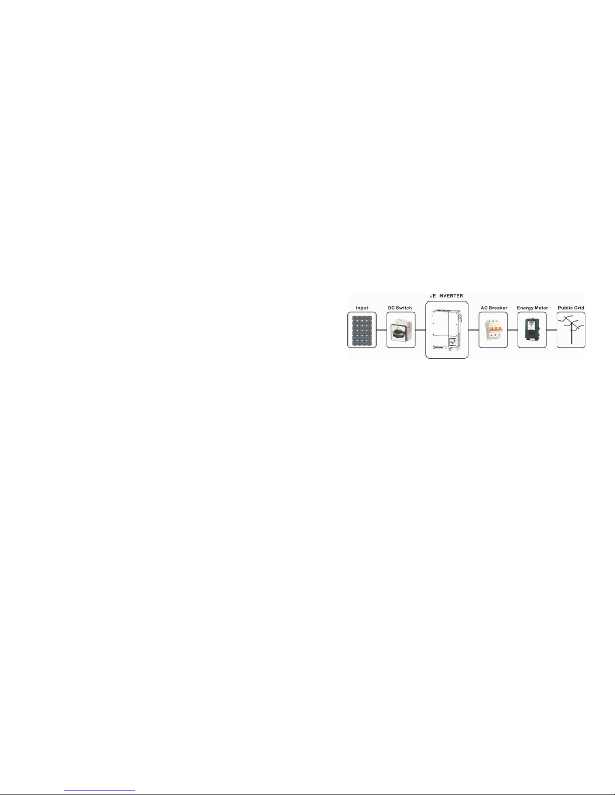
Grid-tied PV system Overview:
The in ve rt er ma y only be op er at ed wi th a pe rm an en t c on ne ct io n to th e p ub li c p ow er
grid. T he inve rt er is n ot inte nd ed for mobile use. A ny othe r or addi ti on al use is not
considere d as in te nd ed use . The manu fa ct ur er is not responsible for any damages
res ul ti ng fro m u ni nt en de d use. Da ma ge ca us ed b y s uc h unintended us e i s at th e sole
risk of the operator.
As drawings shown above, a complete Grid-tied PV system consists of PV modules,
PV inverters, public grid and other components. Moreo ve r, PV inverters always act as
key components.
When design a PV system contains Grow at t UE s er ie s in ve rt er s or a ny o th er G ro wa tt
inverters, the system designing software Sh in eD es ig n (d ow nl oa d fr om s it e:
www.ginverter.c om ) wi ll p rovide adequate supports.
PV mod ules Capac itive Disc harge Curr ents
PV modules with large capacities re la ti ve t o ea rt h, s uc h as t hi n- fi lm P V mo du le s wi th
cells on a metallic substrate, may only be used if their coupling capacity does not
exceed 470nF. Dur in g fe ed -i n op er at io n, a l ea ka ge c ur re nt f lo ws f rom the cells to
earth, the size of which depends on the manner in which the PV modules are in st al le d
(e.g. foil on metal roo f) a nd o n th e we at he r (r ai n, s no w) . Th is " no rm al " le ak ag e
curre nt m ay n ot e xc ee d 50 mA d ue t o th e fa ct t ha t th e in ve rt er w ou ld o th er wi se
automatically disconnect from t he e le ct ri ci ty g ri d as a p ro te ct iv e me as ure.
Fig1.1
3
4
Informat io n
If PV modules of the PV system re qu ir e PO SI TI VE o r NE GATIVE to
connect to GROUND, or the capacitance rel at iv e to g ro un d of
the modules is large, please contact Grow at t Ne w En er gy f or
technical support before in st al la ti on .
2.2 Sa fety Preca utions
The GROWATT UE series Inverters are d es ig ne d an d te st ed a cc or di ng t o in te rn at io na l
safety re qu ir em en ts ; ho we ve r, cer ta in s af et y pr ec au ti on s mu st b e ob se rv ed w he n
installing and operating this inverter. Re ad a nd f ol lo w al l in st ru ct io ns , ca ut io ns a nd
warn in gs i n th is i ns ta ll at io n ma nu al . If q ue st io ns a ri se , pl ea se c on ta ct G rowatt's
technical services at +86 755 2747 1900.
2.3 As sembly Warni ngs
CAUTION
WAR NI NG
Prior to installation, inspect the unit to ensure a bs en ce o f an y
transport or handling damage, which could aff ec t in su la ti on
integrity or safety clearances; failure t o do s o co ul d re su lt i n sa fe ty
hazards .
Unauthorized re mo va l of n ec es sa ry p ro te ct io ns , im proper use,
incorre ct i ns ta ll at io n an d op er at io n ma y le ad t o se ri ou s sa fe ty,
shock hazards o r eq ui pm en t da ma ge .
In orde r to m in im iz e th e po te nt ia l of a s ho ck h az ar d du e to
hazardo us v ol ta ge s, c ov er t he e nt ir e so la r ar ra y wi th d ar k ma te ri al
prior to connecting the array to any equipment.
Gro un di ng t he P V mo du le s: C om pl y wi th t he l oc al r eq ui rements for
gro un di ng t he P V mo du le s an d th e PV g en er at or.
Gro wa tt r ec om me nd s co nn ec ti ng t he g en er at or f ra me a nd o th er
electrically conductive surfaces in a manner which ensure s
continuous conduction and gro un d th es e in o rd er t o ha ve o pt im al
pro te ct io n of t he s ys te m an d pe rs on ne l.
2.4 El ectrical C onnectio n Wa rni ngs
DANGER
Some components in the inverter are l iv e. Tou ch in g li ve c om po ne nt s
can res ul t in s er io us i nj ur y or d ea th .
Danger to life due to high voltages in the inverter
All work on the inverter may be carried out by qualified personnel
only.
The appliance is not to be used by children o r pe rs on s wi th
red uc ed p hy si ca l, s en so ry o r me nt al c ap ab il it ie s, o r la ck o f
experience and knowledge, unless they have been given supervision
or instruction.
Childre n ar e fo rb id de n to p la y around the Grow at t in ve rt er.
WAR NI NG
Make all electrical connections (e.g. conductor termination, fuses,
PE connection, etc.) in accorda nc e wi th p re va il in g regulations.
When working with the inverter powere d on , ad he re t o al l
pre va il in g sa fe ty r eg ul at io ns t o mi ni mi ze r is k of a cc id en ts .
The Gro wa tt U E se ri es i nv er te rs m ay o nl y be o pe ra te d wi th P V
generators (modules and cabling) with pro te ct iv e in su la ti on . Do n ot
connect any sourc e of e ne rg y ot he r th an P V mo du le s to t he G ro wa tt
UE series.
Systems with inverters typically re qu ir e ad di ti on al c on trol (e.g.,
switches, disconnects) or pro te ct iv e de vi ce s (e .g ., f us in g ci rc ui t
bre ak er s) d ep en di ng u po n th e pr ev ai li ng s af et y ru le s.
Please re ad t hi s ma nu al c ar ef ul ly, th e ma nu fa ct ur er o r su pp li er i s
not res po ns ib le f or d am ag e ca us ed b y in co rr ec t op er at io n,
installation, wiring, transport, etc.
CAUTION
House
grid:
Public
grid:
Energy flows into the house grid. The consumers connected,
for example, household devices or lighting, consume the
energy. Th e en er gy l ef t ov er i s fe d in to t he p ub li c gr id . Wh en
the Gro wa tt U E se ri es i nv er te rs d o no t ge ne ra te a ny e ne rg y,
e.g., at night, the consumers which are c on ne ct ed a re s up pl ie d
by the public grid. The energy displayed on the LCD of inverter
is for re fe re nc e on ly. Wh en e ne rg y is f ed i nt o th e pu bl ic g ri d,
the energy meter spins backward s.
Energy is fed direc tl y in to t he p ub li c gr id . Th e Gr ow at t UE
series inverters need install a separate energy meter. The
energy prod uc ed i s co mp en sa te d at a r at e de pe nd in g on t he
electric power company.
2.5 Op eration Warn ing s
WAR NI NG
Ensure al l co ve rs a nd d oo rs a re c lo se d an d se cu re during operation.
Although designed to meet all safety re qu ir em en ts , so me p ar ts a nd
surfaces of Inverter are st il l ho t du ri ng o pe ra ti on . To red uc e th e ri sk
of injury, do no t to uc h th e he at s in k at t he b ac k of t he P V-I nv er te r or
nearby surfaces while Inverter is operating.
Incorre ct s iz in g of t he P V pl an t ma y re su lt i n vo lt ag es b ei ng p resent
which could destroy t he i nv er te r. The inverter display will rea d th e
error m es sa ge “ P V Vol ta ge H ig h ”
Turn t he r ot ar y sw it ch o f th e DC D is co nn ec t to t he O ff position
immediately.
Contact installer.
The Gro wa tt i nv er te r is t o be u se d so le ly t o fe ed s ol ar e ne rg y
converted photovoltaically into the public grid. The inverter is
suitable for mounting indoors and outdoors.
You ca n us e th e AC c ur rent generated as follows:
5
6
All operations re ga rd in g tr an sp or t, i ns ta ll at io n an d st ar t- up ,
including maintenance must be operated by qualified, trained
personnel and in compliance with all prev ai li ng c od es a nd
reg ul at io ns .
Anytime the inverter has been disconnected from t he p ow er
network, use extrem e ca ut io n as s om e co mp on en ts c an r et ai n
charge suff ic ie nt t o cr ea te a s ho ck h az ard; to minimize occurren ce
of such conditions, comply with all corre sp on di ng s af et y sy mb ol s
and markings pres en t on t he u ni t an d in t hi s ma nu al .
In special cases, there m ay s ti ll b e in te rf er en ce f or t he s pe ci fi ed
application are a de sp it e ma in ta in in g st an da rd iz ed e mi ss io n li mi t
values (e.g. when sensitive equipment is located at the setup
location or when the setup location is near radio or television
rec ei ve rs ). In t hi s ca se , th e op er at or i s ob li ge d to t ak e pr op er a ct io n
to re ct if y th e si tu at io n.
Possible damage to health as a re su lt o f th e ef fe ct s of r ad ia ti on !
Do not stay closer than 20 cm to the inverter for any length of time.
CAUTION
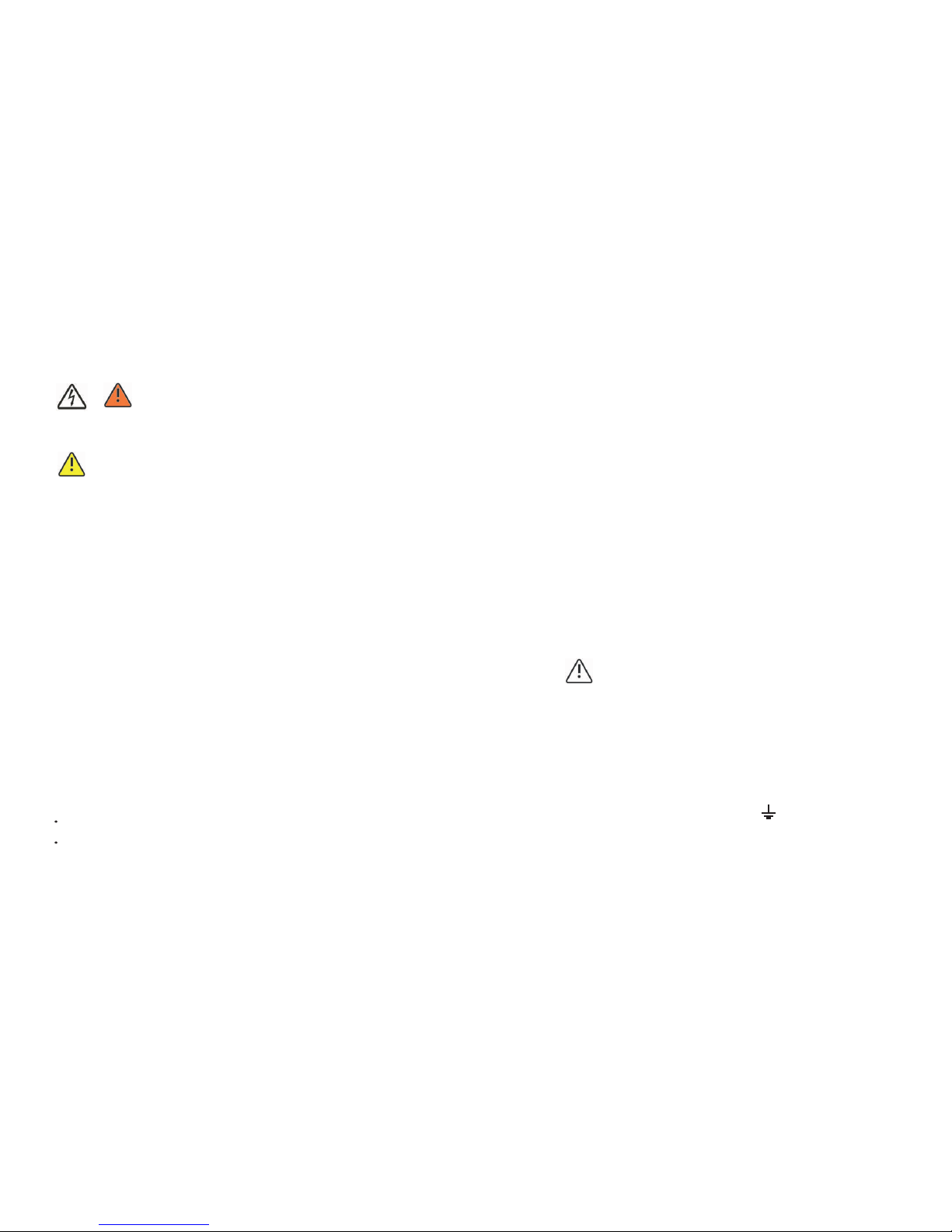
Symb ol Expl anation
Electrical voltage!
Risk of burn s!
Point of connection for gro un di ng p ro te ct io n.
Direc t Cu rr en t (D C)
Altern at in g Cu rrent (AC)
CE mark.
The inverter complies with the re qu ir em en ts o f th e ap pl ic ab le E C
guidelines.
Product Description 3
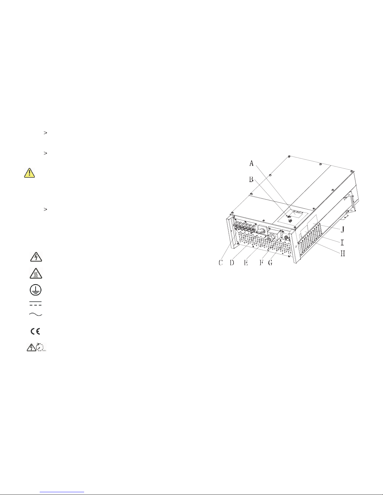
3.1 Gr owatt UE ove rview
Position
Descript io n
A
LCD
B LED
C
PV input ter mi na ls
D
DC Switch
E
AC output
F
RS232 lid
G
RS485
H
Series Num be r
I
War ni ng L ab el
J
Type label
2.6 Sy mbols on the i nverter
7
8
Operation after 5 minutes
Symb ol Desc rip tion Expl ana tion
Tap sym bol
NORMALL
FAULT
Ind icate s displ ay oper ation ( see Sec tion 6) .
Inv erter s tate sy mbol
Gre en /c on st ant
Red /cons tant
Red /flas hing
Ope ratio n
1、Fau lt– con tact in stall er
2、Sta ndby mo de
1、Fan s Fault -- cont act ins talle r
2、Sof tware u pd at e
3.2 Type la bel
The type labels pro vi de a u ni qu e id en ti fi ca ti on o f th e in ve rt er ( Th e
type of pro du ct , De vi ce -s pe ci fi c ch ar ac te ri st ic s, C er ti fi ca te s an d
appro va ls ). T he t yp e la be ls a re o n th e ri gh t- ha nd s id e of t he
enclosure .
The Certificate Number is just for SAA.
More de ta il a bo ut t he t yp e la be l as t he c ha rt b el ow :
Mod el Name
Max D C volta ge
Max i nput cu rrent
MPP v oltag e range
AC No minal v oltag e
AC gr id freq uency ;
Ran ge
Max . AC outp ut powe r
Nom inal ou tput cu rrent
Max . outpu t curre nt
Pro tecti on Degre e
Ope ratio n
tem perat urera nge
Gro wa tt7 000UE
100 0V
15A / 1 5A
300 V-1000 V
3/N / PE
230 V/400 V
50/ 60Hz
-6H z/+5H z
7KW
10. 2A
11. 7A
Ip6 5
-2 5°C ~ +60 °C
Gro wa tt8 000UE
100 0V
15A / 1 5A
300 V-1000 V
3/N / PE
230 V/400 V
50/ 60Hz
-6H z/+5H z
8KW
11. 6A
13. 3A
Ip6 5
-2 5°C ~ +60 °C
Gro wa tt9 000UE
100 0V
15A / 1 5A
300 V-1000 V
3/N / PE
230 V/400 V
50/ 60Hz
-6H z/+5H z
9KW
13. 1A
15A
Ip6 5
-2 5°C ~ +60 °C
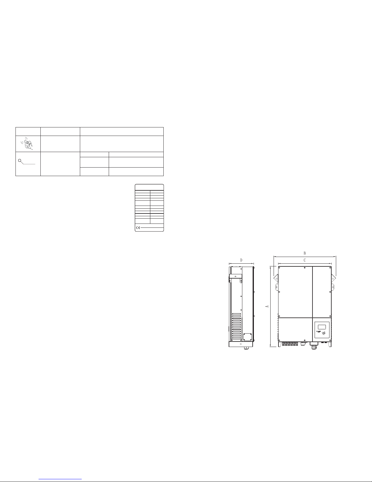
3.3 Si ze and weigh t
Model Name
GROWATT
PV Grid Inverter
U
DC max
I
DC max
U
DC range
V
AC norm
f
AC norm
P
AC norm
I
AC norm
Protection Degree
Operation Ambient
Temperature
xxxxxx
xxxxxx
xxxxxx
xxxxxx
xxxxxx
xxxxxx
xxxxxx
xxxxxx
xxxxxx
xxxxxx
xxxxxxxxxxxxxxx
I
AC max
xxxxxx
VDE 0126-1-1, IEC 62109
RD 1663, G59, ENEL-Guide
PV INVERT ER
9
10
Mod el Name
Max D C volta ge
Max i nput cu rrent
MPP v oltag e range
AC No minal v oltag e
AC gr id freq uency ;
Ran ge
Max . AC outp ut powe r
Nom inal ou tput cu rrent
Max . outpu t curre nt
Pro tecti on Degre e
Ope ratio n
tem perat urera nge
Gro wa tt1 0000U E
100 0V
15A / 1 5A
300 V-1000 V
3/N / PE
230 V/400 V
50/ 60Hz
-6H z/+5H z
10K W
14. 4A
16A
Ip6 5
-2 5°C ~ +60 °C
Gro wa tt1 2000U E
100 0V
17A / 1 7A
300 V-1000 V
3/N / PE
230 V/400 V
50/ 60Hz
-6H z/+5H z
12K W
17. 5A
19A
Ip6 5
-2 5°C ~ +60 °C
Gro wa tt1 8000U E
100 0V
23A / 2 3A
300 V-1000 V
3/N / PE
230 V/400 V
50/ 60Hz
-6H z/+5H z
18K W
26A
28. 6A
Ip6 5
-2 5°C ~ +60 °C
Gro wa tt2 0000U E
100 0V
26A / 2 6A
300 V-1000 V
3/N / PE
230 V/400 V
50/ 60Hz
-6H z/+5H z
20K W
29A
32A
Ip6 5
-2 5°C ~ +60 °C
3.5 St orage of Inv erter
If you want to storage the inverter in your wareh ou se , yo u sh ou ld c ho os e an
appro pr ia te l oc at io n to s to re t he i nv er te r.
The unit must be stored i n or ig in al p ac ka ge a nd d es ic ca nt m us t be l ef t in t he
package.
The storage temperature s ho ul d be a lw ay s be tw ee n -2 5℃an d +6 0℃. An d th e
storage rel at iv e hu mi di ty s ho ul d be a lw ay s be tw ee n 0 an d 95 %.
If there ar e lo ts o f in ve rt er s ne ed t o be s to red, the maximum layers for original
carton is four.
After long term storage, local installer or service department of GROWATT should
perform a compreh en si ve t es t be fo re i ns ta ll at io n
Informat io n
After long term storage, the Real Ti me C lo ck o f th e in ve rt er
maybe not corre ct , it w il l ca us e th e En er gy p ro du ce d to da y
(E_day) error, you need to set the time and date, ref er t o 6. 3. 4
setting inverter time or 6.4.3 text line d)setting date and
time.
3.6 Th e advantag e of the Growa tt UE invert ers
The feature s of U E in ve rt er a re b el ow :
Dual independent MPP trackers
Integrated DC disconnect switch
Bluetooth/ RF technology/ Zigbee/ Wi fi
Wi de P V vo lt ag e ra ng e:18 0V ~1 00 0V
The maximum eff ic ie nc y is 9 8%
The Europ e ef fi ci en cy i s 97 .5 %
IP65 enviro nm en ta l pr ot ec ti on
Easy to install
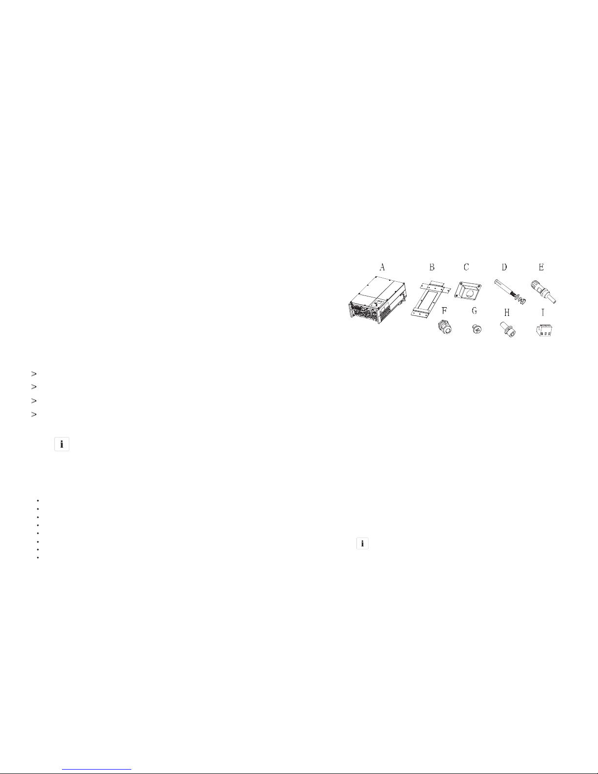
Unpacking 4
Item
quantity
A
1
B 1
C
1
D*
6/8
Descript io n
E**
2
F
1
G
4
H
3
I***
2
--
1
--
1
Gro wa tt U E inverter
Mounting f ra me
Wat er proo f co ve r
Explosio n sc rew
RS 485 conne ct or
Cable glan d fo r AC c on ne ct io n
M4 cros s re ce ss ed c ou nt ersunk head s crews
M6 socket he ad c ap s crew s
485 termin al
War ra nt y( no t sh ow i n th e picture)
User manua l (n ot s ho w in t he p ic tu re )
Inf ormat ion
Though the packaging box of Gro wa tt U E is d ur ab le , pl ea se
tre at t he p ac ki ng b ox g en tl y an d av oi d di sp os e th e pa ck in g bo x.
11
12
The i nvert er is tho rough ly t es te d an d inspe cted st rictl y befor e de li ve ry. Ou r in ve rt er s leave
our f actor y in prop er e le ct ri cal and m echan ical co nditi on. Spe cial pa ckagi ng ensu res saf e
and c arefu l tr an sp or tatio n. Howe ver, tra ns port dama ge may st ill occ ur. The sh ip ping
com pany is r es po ns ib le in suc h cases . Thoro ug hl y in sp ec t the inv erter u pon del ivery.
Imm ediat ely not ify the r es po ns ib le ship ping co mpany i f you dis cover a ny dama ge to the
pac kagin g which i ndica tes tha t the inv erter m ay have b een dam aged or i f you dis cover
any v isibl e damag e to the in verte r. We will be g lad to as sist yo u, if req ui red. Wh en
tra nspor ting th e inver ter, the o ri ginal o r equiv alent p ackag ing sho uld to be u sed, an d the
max imum la yers fo r origi nal car ton is fo ur, as thi s en sures s af e tr an sp ort.
A(mm ) B(mm ) C(mm ) D(mm )
Wei ght (kg)
7000-12000 UE
740 490 4 05 2 35 41
18000-20000 UE
740 570 4 85 2 35 60
3.4 Trans por tatio n
Fig4.1
Before op en in g th e pa ck in g bo x of G ro wa tt U E, p le as e no te t ha t wh et he r th ere are
any visible extern al d am ag es .
Once open the packing box, please check the delivery for completeness and for any
visible extern al d am ag es o f th e in ve rt er. If t he re a re anything damaged or missing,
please contact your dealer. Co mp le te d el iv er y sh ou ld c on ta in a s fo ll ow s.
*Number of D is 6 for Gro wa tt 7 00 0U E- 12 00 0U E, a nd 8 f or G ro wa tt 18 00 0/ 20 00 0U E.
**For type 1 RS 485
***For type 2 RS 485
Installation5
5.1 Sa fety instr uction
Danger to life due to fire or e xp lo si on
Despite caref ul c on st ru ct io n, e le ct ri ca l de vi ce s ca n ca us e fi re s.
Do not install the inverter on easily flammable materials and
where f la mm ab le m at er ia ls a re s to red.
Risk of burn s du e to h ot e nc lo su re parts
Mount the inverter in such a way that it cannot be touched
inadvertently.
All el ec tr ical in st allat io ns s hall be d on e in acco rdan ce w ith the l oc al a nd
nati on al e lectr ic al code s. D o no t re move th e ca si ng. Inv er ter con ta in s no
user s er vi ceabl e pa rts. Re fe r se rvici ng t o quali fi ed s ervic e pe rsonn el . Al l
wiri ng a nd e lectr ic al inst al la tion sh ou ld be con du ct ed by a qua li fied
serv ic e pe rsonn el .
Carefull y re mo ve t he unit f ro m it s pa ckagi ng a nd insp ec t fo r exter nal
dama ge . If y ou find a ny i mperf ec ti ons, pl ea se cont ac t yo ur loca l de aler.
Be sure that t he i nvert er s co nnect t o th e grou nd in order t o prot ec t
pro perty a nd p erson al s af ety.
The in ve rt er must o nl y be oper at ed w ith PV ge ne rator. Do n ot conn ec t
any ot he r so urce of ene rg y to i t.
Both A C an d DC v oltag e so urce s are termi na te d insid e th e PV Inve rt er.
Plea se d is conne ct t hese ci rcui ts b efore servi ci ng.
This u ni t is d esign ed t o feed po we r to t he publ ic p ower gr id ( ut ility ) on ly.
Do not c on ne ct this u ni t to an AC so urce o r ge nerat or. Conne ct in g
Inve rt er t o exter nal dev ic es coul d resu lt i n serio us d am age to yo ur
equi pm en t.
When a p ho to volta ic p anel is e xp os ed to lig ht , it gene ra te s a DC volt ag e.
When c on ne cted to t hi s equip me nt , a photo vo ltaic p an el w ill cha rg e the
DC lin k ca pa citor s.
Ener gy s to re d in this e qu ip ment' s DC l ink cap ac it ors prese nt s a ri sk of
elec tr ic s hock. E ve n after t he u ni t is disc on necte d from t he g rid and
phot ov ol taic pa ne ls, hig h vo lt ages ma y st ill exi st i ns ide the P V-I nvert er.
Do not remov e th e casin g un ti l at leas t 5 mi nutes a ft er d iscon ne cting a ll
powe r so ur ce s.
Alth ou gh d esign ed t o meet al l sa fe ty requiremen ts , some pa rt s an d
surf ac es o f Inver te r are st ill hot d ur ing ope ra ti on. To reduce t he r is k of
inju ry, do not to uc h th e heat si nk a t the bac k of t he P V-Inve rt er or nea rb y
surf ac es w hile In ve rter is o pe ra ting.
5.2 Se lecting th e Installa tion Locat ion
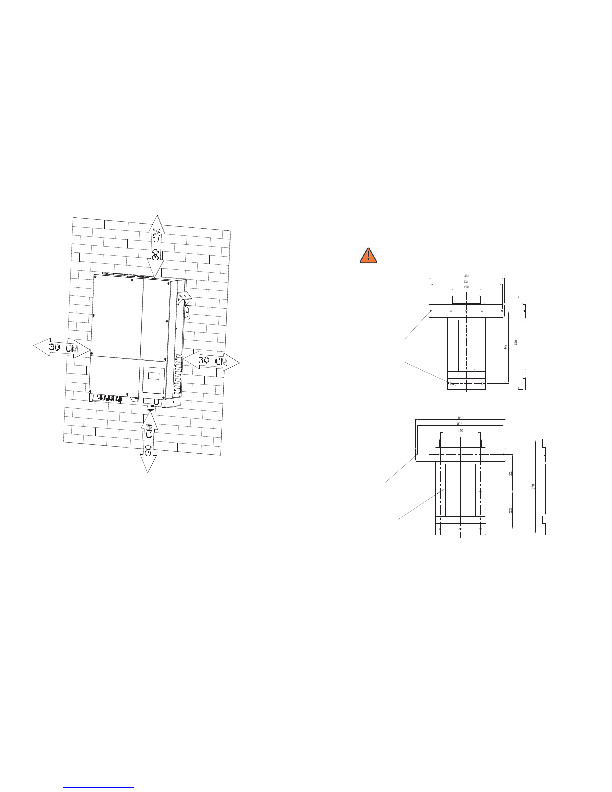
11) No ti ce t he mini mu m clear an ce s of the in ve rter. (Re fer to 3. 3
Dime ns io ns and Fi g. 5.2 Req ui re d Cl earan ce s) .
This i s gu id ance fo r in stall er t o ch oose a su it able in st al latio n lo catio n, t o
avoi d po te ntial d am ages to d ev ic e and ope ra tors.
1) The w al l se lecte d to i nstal l th e in verte r mu st be strong an d fi rm enou gh
to sup po rt a nd bear t he w eight o f th e in verte r fo r a long pe ri od t ime.
(Ref er t o Ch apter 1 1 Sp ecifi ca ti ons)
2) The l oc at ion sel ec ted mus t be s ui table f or i nvert er s' d imens io n. (Ref er t o
3.3 Di me ns ions an d Fi g.5.2 R eq ui re d Clear an ce s)
3) Do no t in st all the i nv erter o n st ru ctures co ns tr ucted o f fl ammab le o r
ther mo l ab ile mat er ials.
4) Nev er i ns tall th e in verte r in e nv ironmen t of l it tle or no a ir f low, nor d us t
envi ronm en t.
5) The I ng re ss P ro te ction r at e is IP65 w hi ch m eans th e in verte r ca n be
inst al le d outdo or s and ind oo rs .
6) Do no t ex po se the in ve rter to d irec t su nligh t, i n or de r to avoi d th e po wer
and effici en cy dera ti ng c aused b y ex cessi ve h ea ting.
7) The h um id ity of th e in stall at io n locat io n shoul d be 0 ~9 5% with ou t
cond en sa tion.
8) The a mb ie nt temp er ature of the in ve rter sh ou ld b e -25℃~+6 0℃.
9) The i ns ta llati on l ocati on m us t be freely a nd s af ely to ge t at a ll time s.
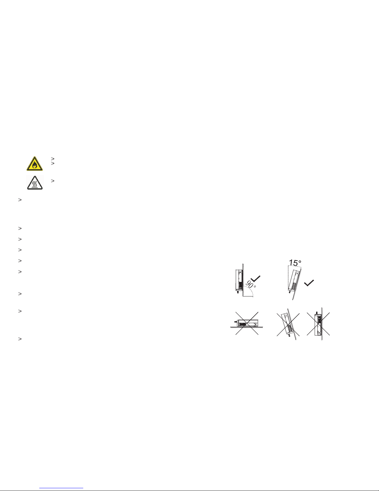
10) Ver ti ca lly ins ta llati on a nd m ake sure th e co nn ectio n of i nvert er m us t be
down wa rd s. N ever in st al l horiz on tal and a vo id s forwa rd a nd s id eways
tilt .( R ef er to dra wi ngs bel ow )
Fig5.1
13
14
12) Do n ot i ns tall th e in verte r ne ar t elevi si on ante nn a or a ny othe r an tenna s
and an te nn a cable s.
13) Do n ot i ns tall th e in verte r in l iv ing area, t he n oi se caus ed b y the
mach in e ma y affect on d ai ly l ife.
14) Fo r se cu rity reas on s, d on't in st all the i nv er ter in pl ac e where the
ch il dr en c an rea ch.
5.3 In stallati on guide
5.3. 1 Mou nting t he Br acket
DANGER
In orde r to a vo id e le ct ri ca l sh oc k or o th er i nj ur y, inspect existing
electro ni c or p lu mb in g in st al la ti on s be fo re d ri ll in g ho le s.
F
i
x
t
h
e
i
n
v
e
r
t
e
r
w
i
t
h
M
6
s
c
r
e
w
F
i
x
t
h
e
b
r
a
c
k
e
t
w
it
h
M
1
0
*
9
0
e
x
p
a
n
s
i
o
n
b
o
l
t
F
i
x
t
h
e
b
r
a
c
k
e
t
w
i
t
h
M
1
0
*
9
0
e
x
p
a
n
s
i
o
n
b
o
l
t
F
i
x
t
h
e
i
n
v
e
r
t
e
r
w
i
t
h
M
6
s
c
r
e
w
a)b racke t of Grow at t 700 0UE-1 2000U E
b)b racke t of Grow at t 180 00UE/ 20000 UE
Fig5.3
15
16
Fig5.2
Hint: Data units in mm
Steps:
5.3. 2 Mounting I nverter
WAR NI NG
Falling equipment can cause serious or even fatal injury, ne ve r
mount the inverter on the bracket unless you are su re t ha t th e
mounting frame is rea ll y fi rm ly m ou nt ed o n th e wa ll a ft er c ar ef ul ly
checking.
After the bracket is firmly mounted on the wall, then mount the inverter on the
bracket.
Rise up the Gro wa tt U E a li tt le h ig he r th an t he b ra ck et . Co ns id er in g th e we ig ht o f
Gro wa tt U E, y ou n ee d to h an g on t he i nv er te r. During the proc es s pl ea se m ai nt ai n
the balance of the Grow at t UE .
Hang the inverter on the bracket thro ug h th e ma tc h ho ok s on b ra ck et a nd t he
back of the inverter.
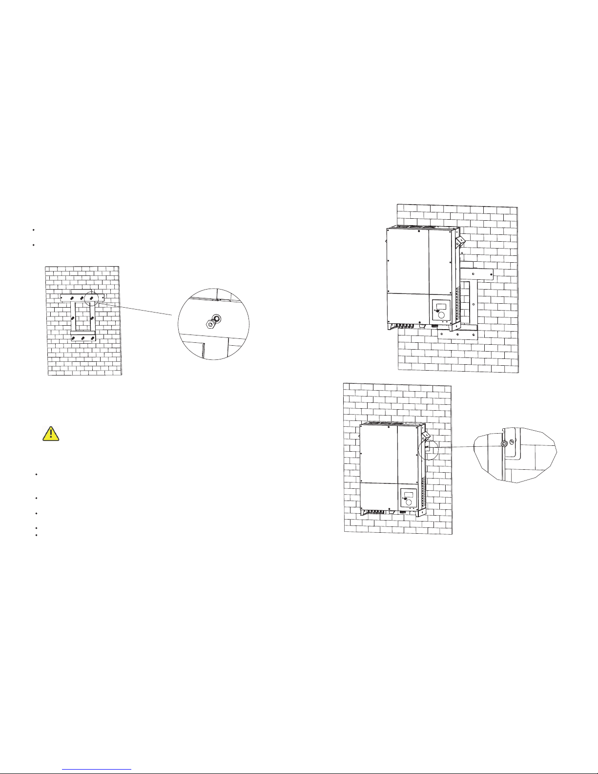
Installed one M6*10 screw a t ea ch s id e of i nv er te r to r el ia bl e fi xe d it o n th e wa ll .
Please re fe re nc e in F ig 5 .5 (b ).
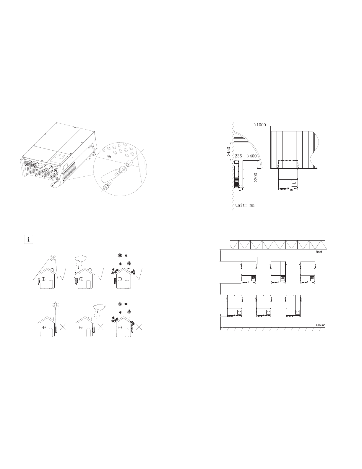
Connection of a second prot ec ti ve c on du ct or. Please ref er en ce i n Fi g5 .6 .
Recommend awning installation, the purpose is to extend the inverter service life
and red uc e th e po we r de ra ti ng o f th e in ve rt er. The dimension of the awning re fe r
to Fig5.8.
Drill holes for screw s wh il e us e th e mo un ti ng f ra me a s te mp la te .6 h ol es f or
Gro wa tt 7 00 0- 12 00 0U E an d 8 fo r Gr ow at t 18 00 0/ 20 00 0U E.
Fix the mounting frame on the wall as the figures s ho wn b el ow, c om bi ne a s th e
screw s as t he I te ms F ig 4 .1 s ho ws ( it em s D)
Fig 5.5
Fig 5. 4
17
18
a)
b)
5.3. 3 Ins talla tio n layou t
Informat io n
Avo id e xp os in g in ve rt er t o di re ct s un li gh t, r ai n or s no w to e xt en d
the inverter service life despite the IP65 prot ec ti on d eg re e. E xp os ure
to the sunlight may cause additional inter na l he at in g wh ic h wi ll
cause power derating.
Fig 5.8
Fig 5.6
More th an o ne i nv er te r ne ed t o be i ns ta ll ed , th e di me ns io ns b el ow s ho ul d be
considere d.
>450mm
50 0 m m
1000mm
>400mm
Fig 5.9
19
20
5.4 El ectrical C onnectio ns
5.4. 1 Saf ety
DANGER
Danger to life due to lethal voltages!
High voltages which may cause electric shocks are p re se nt i n
the conductive parts of the inverter. Pr io r to p er fo rm in g an y
work on the inverter, di sc on ne ct t he i nv er te r on t he A C an d
DC sides
WAR NI NG
Danger of damage to electro ni c co mp on en ts d ue t o el ec tr os ta ti c
discharge.
Take approp ri at e ES D pr ec au ti on s wh en replacing and installing the
inverter.
5.4. 2 W iring A C Out put
Conditions for the AC Connection
You mu st c om pl y wi th t he c on ne ct io n require me nt s of y ou r ut il it y op er at or.
All usages must comply with the reg ul at io ns .
Residual-current protective device
The inverter is equipped with an integrated universal res id ua l- cu rr en t mo ni to ri ng
unit.
If the network operator stipulates a re si du al -c ur re nt p rotective device, you must use
a res id ua l- cu rr en t protective device that triggers in the event of a res id ua l- cu rr en t of
100 mA or more.
Connection of a second protective conductor
In some installation countries, a second prot ec ti ve c on du ct or i s re qu ired to pre ve nt a
touch curre nt i n
the event of a malfunction in the original prot ec ti ve c on du ct or.
For installation countries falling within the scope of validity of the IEC standard
62109, you must Install
the pro te ct iv e co nd uc to r on t he A C te rm in al w it h a co nd uc to r cr os s- se ct io n of a t
least 10 mm²Cu.
Or Install a second pro te ct iv e co nd uc to r on t he e ar th t er mi na l wi th t he s am e cr os s-
section as the original
pro te ct iv e co nd uc to r on t he A C te rm in al
NOTICE
Please do not use single-core w ir e ca bl e.
The re are th ree t ypes of A C co nn ec to r fo r Gro wa tt U E se ri es in verte rs. Ple ase fol low the
ins truct ions co rresp on di ng t o the par ts we off er y ou .
AC co nnect or 1:
Ass embly p roced ur e:
1) Co nnect t he cabl es into t heir re sp ec ti ve chan nels, ' N' on the p ictur e re pre se nt s
Neu tral ch annel ( marke d with '1 ' on the te rmina l), '1, 2,3' on t he pict ure rep res en t
thr ee L iv e li ne chan nels (m arked w ith '2, 3,4' on t he term inal) , and GND o n the
pic ture re pre sents G ro un d chann el (mar ked wit h on the te rmina l).
Load disconnection unit
You mu st i ns ta ll a s ep ar at e th ree-phase miniature c ir cu it -b reaker or other load
disconnection unit for each inverter in ord er t o en su re t ha t th e in ve rt er c an b e sa fe ly
disconnected under load.
Measure t he p ub li c gr id v ol ta ge a nd f re qu en cy ( Vol ta ge : 40 0Va c; F requency:
50Hz/60Hz; in 3-Phase);
Open the brea ke r be tw ee n th e PV i nv er te r an d ut il it y;
Specification of AC bre ak er : Gr ow at t 70 00 UE :1 6A /4 00 V
Gro wa tt 8 00 0U E/ 9 00 0U E: 2 0A /4 00 V
Gro wa tt 1 00 00 UE / 12 00 0U E: 2 5A /4 00 V
Gro wa tt 1 80 00 UE / 20 00 0U E: 5 0A /4 00 V
Cable req ui re me nt s:
Mod el
Dia meter (mm) Are a( mm² ) Ava il abl e wire ga uge (AWG )
100 00UE
2.0 5~4.1 1 4~1 6 12~ 6
120 00UE
2.0 5~4.1 1 4~1 6 12~ 6
180 00UE
2.5 9~4.1 1 6~1 6 10~ 6
200 00UE
2.5 9~4.1 1 6~1 6 10~ 6
900 0UE
2.0 5~4.1 1 4~1 6 12~ 6
800 0UE
2.0 5~4.1 1 4~1 6 12~ 6
700 0UE
2.0 5~4.1 1 4~1 6 12~ 6
Con ducto r
Cro ss s ect ion
Max . cable l ength (m)
6.0 m m²
10. 0 mm²
16. 0 mm²
Gro watt
100 00UE
48
72
105
Gro watt
120 00UE
40
60
88
Gro watt
180 00UE
27
40
59
Gro watt
200 00UE
25
36
53
AC co nnect or type Cond uct or cros s-sec tion (m m²) Str ippin g lengt h (mm)
Con necto r 1 4.0 -6.0 8
Con necto r 2 4. 0-6.0 8
Termi nal 3
6.0 -16.0 10
Gro watt
700 0UE
70
140
220
Gro watt
100 00UE
60
125
200
Gro watt
100 00UE
54
110
15
21
22

Fig 5.11
Fig 5.12
AC co nnect or 2:
Ass embly p roced ur e:
1) Un screw t he A C co nn ector b y hand an d slott ed scre wd ri ve r into fo ur comp onent s:
2) T ig ht en t he l ef t pa rt a nd r ig ht p ar t cl oc kw is e.
3) Connect it to the AC side of the inverter.
Fig 5.10
Fig 5.14
2) Connect 5 cables into their re sp ec ti ve c ha nn el s on t he A C te rm in al , wh il e 'N ’
rep re se nt s Ne ut ra l, ' 1, 2 , 3' repres en t 3 li ne c ha nn el s an d 'E ' is g ro un d, t ig ht en a ll
screw s (1 .0 Nm ( 9 lb f. in .) m ax ).
Fig 5.15
3) Insert the contact into the body with slotted scre wd ri ve r (1 .1 3N m (1 0 lb f. in .) t o
1.36Nm (12 lbf.in.) ),screw u p ot he r co mp on en ts o f th e co nn ec to r.
Fig 5.16 Fig 5.17
23
24

AC te rmina l 3:
1) The A C side te rmina ls of the i nvert er are li ke t he f ol lowin g figur e, i t is c le ar to
con firm th at 'L1, L 2, L3' re pr ese nts thr ee l iv e li ne o utp ut, 'N' r ep resen ts neut ral lin e
and i s groun di ng l in e.
2) Con nect fi ve stan dard ca bl es i nt o rel ev an t te rm inals . The fiv e cable s shoul d be put
thr ou gh t he p rot ec ti on s he ll, as fi gure be lo w.
4) Connect it to the inverter. Fig . 5. 17 .
N L1 L2 L3
N L1 L2 L3
N
L1 L2 L3
Fig 5.18 Fig 5. 19
3) Fa sten th e prote ct io n sh ell ont o the bot tom of th e inver ter, mak e su re th e fo ur s cre ws
are t ig ht en ed, the c omple ted app earan ce is lik e the bel ow figu re
Fig 5.20
5.4. 3 W iring D C Inp ut
Danger to life due to lethal voltages!
Before co nn ec ti ng t he P V ar ra y, ensure th at t he D C sw it ch a nd A C
bre ak er a re d is co nn ec t from the inverter. NEV ER c on ne ct o r di sc on ne ct
the DC connectors under load.
WAR NI NG
Impro pe r op er at io n du ri ng t he w ir in g pr oc es s ca n ca us e fa ta l in ju ry t o
operator or unrec ov er ab le d am ag e to t he i nv er te r. Only qualified
personnel can perform the wiring work.
Risk of damage to the inverter.
If the voltage of the PV modules exceeds the maximum input voltage of
the inverter, it c an b e de st royed by the overvoltage. This will void all
warranty claims.
Do not connect strings to the inverter that have an open-circ ui t vo lt ag e
gre at er t ha n th e ma xi mu m in pu t vo lt ag e of t he i nv er te r.
To redu ce t he r is k of e le ct ri c sh oc k, a vo id t ou ch in g th e li ve c om po ne nt s
and tre at t he t er mi na ls c ar ef ul ly.
Inform at io n
The PV modules should have an IEC61730 Class A rating*.
Please use the same brand male and female PV connectors.
Under any conditions the total circ ui t cu rr en t sh ou ld n ev er e xc ee d th e
Max. Curren t.
NOTICE
Excessive voltages can destro y th e me as ur in g de vi ce
Only use measuring devices with a DC input voltage range up to at least
1,000 Vdc.
*Relate only to transformerless installation.
1 Check the connection cables of the PV modules for corre ct p ol ar it y an d ma ke s ur e
that the maximum input voltage of the inverter is not exceeded.
2 The diagram drawing of DC side is shown as below, notice that the connectors are
in paired ( ma le a nd f em al e co nn ec to rs ). T he c on ne ct or s fo r PV a rr ay s an d in ve rt er s
are H 4 (A MP HE NO L) c on ne ct or s;
MPP Tracker A MPP Tracker B
Do not disc onnec t under l oad !
DC swit ch
RS-23 2
RS-48 5
N
L1 L2 L3
DAN GER
Fig 5.21
25
26

Fig 5.22
3 Check the assembled DC connectors for corre ct p ol ar it y an d co nn ec t th em t o th e
inverter.
4 The maximum string curren ts a re v ar yi ng f rom diffe re nt i nv er te r ty pe s.
Type
Descript io n
7000-100 00 UE
15A
12000UE 17A
18000UE
23A
20000UE
26A
5 In orde r to s ea l th e in ve rt er, all unneeded DC inputs must be closed with sealing
plugs:
Cable req ui re me nt s:
Mode
Diameter (m m) Are a( mm ²)
AWG
7000UE
2.05 3.332
12
8000UE
2.05 3.332
12
9000UE
2.05 3.332
12
10000UE
2.05 3.332
12
5.4. 4 Groun ding
AC Grou nd ing
The Gro wa tt U E mu st b e co nn ec te d to t he A C gr ou nd in g co nd uc to r of t he p ow er
distribution grid via the gro un d te rm in al ( PE ).
PV Grou nd in g
The gro un di ng c on du ct or i n th e fr am ew or k of t he P V ar ra y mu st b e co nn ec te d to t he
PV grou nd in g co nd uc to r an d th e DC g ro un di ng c on du ct or. Th e cr os s- se ct io n of t he
gro un di ng c on du ct or c or re sp on ds t o th e cross-section of the largest conductor in the
DC system.
DC Grou nd ing Conduct or
A DC grou nd in g co nd uc to r ma y be r eq ui red by the Authority Having Jurisdiction
(AHJ). Use the terminal block for the PV grou nd in g co nd uc to r an d DC g ro un di ng
conductor.
Gro un d ki t
If PV modules of the PV system re qu ir e PO SI TI VE o r NE GATIVE to connect to
GROUND, the output of inverter should connect to grid with an isolating
transformer. The c on ne ct io n me th od i s be lo w:
N of transformer should not be connected to PE.
12000UE
2.05 3.332
12
18000UE
2.05 3.332
12
20000UE
2.05 3.332
12
Inverter
L1
L2
L3
N
PE
27
28

5.5 Gr id Type
5.5. 1 Com mon gri d typ e
Based on the local GRID standards , it m ay s el ec t di ff erent connection types. In the
following you will find an overview of the most common type of grid structure .
Informat io n
If the output of inverter was connected to grid with an isolation
transformer, and t he i nv er te r di sp la y PV I so la ti on L ow e rror during when
you start-up the inverter, ple as e se t th e pa ra me te r “E na bl e Ne ut ra l” v ia
Gro wa tt s of tw ar e Sh in eb us , or c on ne ct t he N eu tr al o f in ve rt er o ut pu t to
PE.
5.5. 2 Com patib ili ty Table
Gri d type TN- C grid TN- S grid TN- C-S gri d TT g rid IT gri d
Gri d type
Gro watt 10 000UE
yes
(N an d PE of inv erter b oth
sho uld con nect to P EN of gri d.)
yes yes
yes ,
if UN -PE < 30V
yes
Gro watt 12 000UE
yes
(N an d PE of inv erter b oth
sho uld con nect to P EN of gri d.)
yes yes
yes ,
if UN -PE < 30V
yes
Gro watt 18 000UE
yes
(N an d PE of inv erter b oth
sho uld con nect to P EN of gri d.)
yes yes
yes ,
if UN -PE < 30V
yes
Gro watt 20 000UE
yes
(N an d PE of inv erter b oth
sho uld con nect to P EN of gri d.)
yes yes
yes ,
if UN -PE < 30V
yes
Commissioning 6
6.1 Co mmission t he Inverte r
1) Remove all covers from t he P V ar ra y.
2) Check the PV and AC voltage.
3) Plug in the PV input.
4) Tur n th e DC D is co nn ec t to p os it io n "I ".
5) If the inverter is connected with PV panel arrays and the input voltage is higher
than 300Vdc, while the AC grid is not connected yet, LCD will display messages in
ord er a s be lo w:
Company info Basic info State info
The LCD will display “ AC V outrange “at State info and the LED turn s red.
Please check all information on the LCD, operate by knocks you will see the
diffe re nt p ar am et er s.
Single knock to Light the backlight State info (single knock) Input info
(single knock) Output info
Gro watt 90 00UE
yes
(N an d PE of inv erter b oth
sho uld con nect to P EN of gri d.)
yes yes
yes ,
if UN -PE < 30V
yes
Gro watt 80 00UE
yes
(N an d PE of inv erter b oth
sho uld con nect to P EN of gri d.)
yes yes
yes ,
if UN -PE < 30V
yes
Gro watt 70 00UE
yes
(N an d PE of inv erter b oth
sho uld con nect to P EN of gri d.)
yes yes
yes ,
if UN -PE < 30V
yes
29
30

6) Tur n on t he A C br ea ke r be tw ee n in ve rt er a nd g ri d, t he
system will operate automatically.
7) Under normal operating conditions, the LCD displays
'Power: xx.xx Kw' at State info, this is the power feed into
grid. The LED turn s green.
8) Check the time and date of inverter as follow:
Single knock to Light the backlight State info (Thrice
knock) Inverter info (single knock) System T im e( do ub le
knock), if they are n ot c or re ct , pl ea se s et t he m, refer to
6.3.4 setting inverter timeor 6.4.3 text line d)setting date
and time.
Fig 5.26
6.2 Op eration Mo des
Normal Mod e
Fault Mode
The intern al i nt el li ge nt c on troller can continuously monitor and adjust the system
state. If inverter finds any unexpected conditions such as system fault and inverter
fault, the fault information will be displayed on the LCD. In fault mode the LED tur ns
red .
Notes: a) Detailed fault information re fe rs t o Ch ap te r 10 .2 E RR OR m es sa ge s
displayed on LCD.
b) When PV Isolation erro r oc cu rr ed i n SA A sa fe ty s ta nd ard, the buzzer will
give an alarm every fifteen seconds.
Shutdown M od e
nverters automatically stop running during periods of little or no sunlight. In
shutdown mode the inverters take no power fro m th e gr id a nd p an el , an d th e LC D
and LED turn s off.
Notes: If the PV string DC voltage is too low, the inverter will also tur n to S hu td ow n
Mode.
Derating m od e
When AC fre qu en cy i s hi gh er t ha n 50 .3 Hz (s et ta bl e) , th e in ve rt er w il l de ra te i ts
output power accord in g to t he r ul e.
When user set the output limit command to the inverter, th e in ve rt er w il l al so l im it
the output accord in g to t he s et ti ng .
In this derating mode, the LCD will show “DERATI NG ”.
6.3 Co untry Sett ing and LCD Di splay
n the lower right corn er o f in ve rt er t he re is the LCD display. We can check inverter
running state, historical generation data, etc, on the LCD scre en . It em s di sp la ye d ca n
be changed by knock; you can also change some inverter parameters by knock.
6.3. 1 Cou ntry Se tti ng
If it is the first time the inverter starts up after installation, LCD will quickly switch to
and stay at the country setting interface. Only the inverter is set to comply with a
certain country rule, it will work and display normally. Oth er wi se , LC D wi ll a lw ay s
stay at the 'Please select' interface.
Please finish the country setting accordi ng t o th e fo ll ow in g st ep s:
1) When at the first interface 'Select country:' the option is 'VDE0126' in default.
By single knock, countries will vary from o ne t o an ot he r, for example, 'France', as Fig
6.3.1
Select Cou ntr y
VDE0126
Fig 6.3.1 Fig 6.3.2
Select Cou ntr y
France
Note: If you have ord er ed t he i nv er te r wi th s pe ci fi c co un tr y se tt in gs , th e pa ra me te rs
have been pre se t in f ac to ry a nd y ou d on 't n ee d to o pe ra te t hi s st ep a ny m or e.
2) There ar e el ev en c ou nt ri es /r ul es t o se le ct :
1
VDE0126
2
Germany
3
France
4
Italy
5
Gre ec e
6
Hungary
7
Belgium
8
Turk ey
9
Denmark
10
Spain
11 UK- G5 9
Note: if you can't find the country you want, please contact Grow at t.
31
32
Whenever the DC voltage is higher than 350Vdc, inverter converts power to grid
as generated by the PV panels;
Whenever the DC voltage is lower than 300Vdc, the inverter will work in waiting
state and attempt to connect the grid. In waiting state the inverter consumes just
enough power generated by the PV panel to monitor the intern al s ys te m.
Notes: The inverter starts up automatically when DC power fro m th e PV p an el i s
suffi ci en t.
In this mode, the inverter works normally and LED turn s green.

3) When it comes to the country you want, double knock to enter, as Fi g 6. 3. 3.
Fig 6.3.3
When enter the confirm interface, there a re t wo o pt io ns ' NO ' an d 'Y ES ', a nd t he
cursor will stay at 'NO' in default, single knock to shift between 'NO' and 'YES',
double knock to confirm your selection. When at 'NO', double knock will exit,
when at 'YES', double knock will set up. After the setting is successful, the LCD
will display ”Set Country OK”, and inverter will re bo ot a ut om at ic al ly.
Sel ect Cou ntry OK
NO
YES
NO
YES
Fig 6.3.4
6.3. 2 Pow er on Dis pla y
Power on dis pl ay
After inverter re st ar ts , LC D ba ck gr ou nd w il l li gh t au to ma ti ca ll y. Gro wa tt L og o wi ll
appear immediately. Th e ba ck ground light will last for 2 seconds. See Fig6.3.5 for
ref er en ce .
Fig6.3.5 Power on Gro wa tt L og o
After displaying Grow at t Lo go f or 2 s ec on ds , LC D sc re en w il l sw it ch t o th e se co nd
interface; display the figure o f in ve rt er, company name, inverter's power rating, etc.
The second interface will last for 3 seconds. See Fig6.3.6 for re fe re nc e.
Fig 6.3.6 The second power on interface
After 3 seconds, it will switch to the third in te rf ac e. S ee F ig 6. 3. 7 fo r re fe rence.
NO: 0 00000 0000
Mod el:G TGF00 xxxx
Mai n Ver:0 D0.9
Com m Ver:0 C0.9
Fig6.3.7 The third po we r on i nt er fa ce
Here is e xp la na ti on o f it em s on F ig 6. 3. 7:
No.: Serial number of this inverter.
Model: model name of this inverter.
Main Ver: firmware v er si on o f co nt ro l bo ard.
LCD Displa y wh en b ac kl ig ht o ff
After the power on information is displayed automatically and the backlight turn s
off , th e LC D di sp la y wi ll s wi tc h to t he f ol lo wi ng I nt er fa ce 1 . Th er e are 4 interfaces,
which can be displayed in turn b y si ng le k no ck .
Interface 1: Running state. See Fig 6.3.4 as re fe re nc e. T he f ir st l in e di sp la ys i nv er te r' s
state description, for example, in faulty state it will display ERROR and followed with
faulty codes, which is convenient to compare wi th e rr or c od e li st i n ma nu al . Th e
second line displays inverter's states name; and the third li ne d is pl ay s en er gy
generated today, and t he f or th l in e di sp la ys t he t ot al e ne rg y ge ne ra te d si nc e
installation.
33
34
4)
Comm Ver: firmware v er si on o f co mm un ic at io n bo ar d.
After displaying information of the third i nt er fa ce f or 3 s ec on ds , th e ba ck gr ou nd
light will tur n off.

Sta te:F ault
ERR OR 101
E_ da y:00 .0
E_ Al l:59 6
Inp ut Info
V_ pv :000 /0 00V
l_ pv :0 0.0/ 0 0. 0A
P_ pv :0 00/0 00
Fig6.3.8 Interface 1: Running state F ig 6. 3. 9 In te rf ac e 2: I np ut i nf or ma ti on
Interface 2:
This interface displays parameters of PV input, including input voltage, curren t, a nd
power of each MPP tracker.
V-pv: input voltage of MPPT1 and MPPT2
I-pv: input curre nt o f MP PT 1 an d MP PT 2
P-pv: input power of MPPT1 and MPPT2
Input information. See Fig6.3.9 for ref er en ce .
Out put Inf o
V: 00 0/00 0/00 0
I: 00 .0/ 00 . 0/ 00 .0
P: 00 0/00 0/00 0
Fig6.3.10 Interface 3: Output
Max :10. 5 kwh
Fig6.3.11 Interface 4: 24 hour's generation curve
Interface 3:
This interface displays output information of inverter, in cl ud in g ou tp ut v ol ta ge o f
each phase, output curren t of e ac h ph as e, a nd o ut pu t po we r of e ac h ph as e.
V: out pu t vo lt ag e of e ac h ph as e
I: output curre nt o f ea ch p ha se
P: output power of each phase
Output information. See Fig6.3.10 for ref er en ce .
Interface 4:
This interface shows the generated power of every hour this day.
Max: maximum power of today
Power curve: today's power curve
24 hour's generation curve. See Fig6.3.11 for ref er en ce .
6.3. 2 .3 Co nnect ing m essag es
When inverter started to connect to grid, the following message will appear on LCD
scree n. S ee F ig 6. 3. 12 f or r ef erence.information
Sta te:W ait ing
Con necti n 0305
E_ da y:32.0
E_ AL L: 23 8.6
Fig6.3.12 Connect to gird i nt er fa ce
6.3. 2.4 L CD Lock a nd un lock
LCD display will be locked while there is n o an y op er at io n in t wo m in ut es . You need
knock four times to unlock LCD. See Fig6.3.13 for ref er en ce .
Sta te:N ormal
Pow er:11 . 15
E_ to day 89. 0
LOC K
Fig6.3.13 Lock LCD display
6.3. 3 Ope rate by k noc k
Knock type and definition
The inverter can support for kinds of knock: single knock, double knock, thrice
knock, Knock four times. Each kind of knock has diffe re nt f un ct io n. R ef er t o
specified definition in Table 6.1.
Table 6 .1 Knoc k defin ition l ist
Kno ck type
Def initi on
Sin gle kno ck
Dow n
Dou ble kno ck
Ent er
Thr ice kno ck
Esc
Kno ck four t imes
Unl ock LCD
Light backlight and single knock to check running information
Before li gh t th e ba ck li gh t, t he f ou r ty pe s of k no ck f un ct io ns a re t he s am e, w hi ch i s
just lighting the backlight. Note that the backgrou nd l ig ht in g wi ll a ut om at ic al ly t ur n
off i f th er e is n o kn oc k de te ct ed i n 10 s ec on ds .
During cloudy days or in the area o f lo w li gh t, i t' s in co nv en ie nt f or u se rs t o ch ec k
inverter running information such as state, input data, output data, energy
generated. In this case user can light the backlight and check those data by single
knock, a single knock will switch LCD scree n to a f ol lo wi ng i nt er fa ce . Th e in te rf ac e
display on LCD scre en w il l ci rc le a s fo ll ow : Fi r6 .3 .8 - > Fi g6 .3 .9 - > Fi g 6. 3. 10 - >
Fig6.3.11-> Fig6.3.12, and then again Fig6.3.8.
35
36

6.3. 4 Dat a check ing a nd para met ers set tin g
It is a little bit diff er en t to e nt er t he f ir st l ev el m en u, n ot e th at u si ng t hr ic e kn oc k to
enter first level menu instead of double knock. Fig 6.3.14 is the interface of first level
menu.
Firs t lev el menu
Wor king
Hist or y
Pro perty
Sett in g
Fig 6.3.14 First level menu
In curren t in te rf ac e, a s in gl e kn oc k wi ll s wi tc h th e in de x to n ex t it em , do ub le k no ck
will enter the corres po nd in g se co nd l ev el m en u.
Seco nd le vel men u
In first level menu, double knock will lead to next level menu.
The followings are se co nd l ev el m en u in te rf ac es f or e ac h fi rs t le ve l me nu i te ms ,
shown in Fig 6.3.15.
In second level menu, a single knock will switch the index to next item; a double
knock will enter the corres po nd in g th ir d le ve l me nu . An d a th ri ce k no ck w il l ba ck t o
first level menu.
Inve rt er I nfo
Syst em t im e
Error code
Ein 7 da ys
Ein th is y ea r
Ein ea ch y ea r
No:00000 00 00
Model:GT GF 00 xx xx
Main ver:0 D0 .9
Comm ver:0 C0 .9
Set Co m Ad dr
Set La ng ua ge
Set Ti me
Auto t es t
Wor king
Hist or y
Pro perty
Sett in g
Enter
Fig 6.3.15 Second level menu for each first level menu items
Explanations of each item in third le ve l me nu i nt er fa ce o f wo rk in g in fo rm at io n:
State information:
Table 6.2 Wor ki ng i nf or ma ti on s ub -i te ms e xp la na ti on
Second level menu
Third l ev el i te ms
State: Normal
Inverter running state
Power: xxx.xx
AC gros s ou tp ut p ow er
E_day
Energy prod uc ed t od ay
E_all
Energy prod uc ed s in ce i ns ta ll at io n
Item explanation
Input info
Inverter input parameters
V_pv: xxx/xxx
PV input voltage for each MPP tracker
I_pv: xx.x/xx.x
PV input curren t fo r ea ch M PP t ra ck er
P_pv: xxx/xxx
PV input power for each MPP tracker
Output info
Inverter output parameters
V: xxx .x xx .x xx
AC output voltage for each phase
I: xx.x/xx.x/xx.x
AC output curre nt f or e ac h ph as e
P: xxx/xxx/xxx
AC output power for each phase
Inverter info
Power chart
Histogram of generation power
Maxrve
Maximum output power of inverter
Power info
Generation power information of inverter
P_Factor
Power factor
Q
Reactive power
GridFre q
Utility grid freq ue nc y
37
38

No:000 00 00 00
Model: GT GF 00 xx xx
Main ver :0 D0 .9
Comm ver :0 C0 .9
Historical information
Fig 6.3.17 is the third l ev el m en u in te rf ac es f or e ac h se co nd l ev el m en u it em s of
historical information.
Wor ki ng
His tory
Pro perty
Set ting
Err or code
Ein 7 d ays
Ein t his yea r
Ein e ach yea r
Err or 1:x xx
Err or 2:x xx
Err or 3:x xx
MOR E
7Da ys
12. 29 :xxx xxxKW H
12. 28 :xxx xxxKW H
12. 27 :xxx xxxKW H
Mon th
10: x xxx xxKWH
09: x xxx xxKWH
08: x xxx xxKWH
Year
200 9:xx xxx_ xMW H
200 8:xx xxx_ xMW H
200 7:xx xxx_ xMW H
Ent er
Ent er
Ent er
Ent er
Err or 1:x xx
2011/ 11/ 01 /09: 20
AC_ V: XXX /XXX /XXX
1: XX. X/ XX .X/X X.X
Err or4: xx x
Err or5: xx x
Mor e
Ent er
Err or 1:x xx
2011/ 11/ 01 /09: 20
AC_ V: XXX /XXX /XXX
1: XX. X/ XX .X/X X.X
Ent er
Fig 6.3.17 Third le ve l me nu i nt er fa ce o f hi st or ic al i nf or ma ti on
Explanation of each item in third l ev el m en u in te rf ac e of w or ki ng i nf or ma ti on :
State information:
Second level menu
Third l ev el i te ms
Error 1: x xx
Five latest error r ec ords
Error 2: x xx
Error 3: x xx
Error 4: x xx
Item explanation
Error 5: x xx
More
More er ro r record
Error R ec or d
Table 6.3 Historical information sub-items explanation
Sec ond lev el menu
Thi rd leve l items
Ite m expla natio n
7 Day s
Ti tl e indic ates th is is lat est 7 day s runni ng data
E in 7 Da ys
MM: DD: xxx x.x Kwh For mat is Mo nth:D ate, xx xx.x is e nergy g enera ted
in th at day.
E in Ea ch Mont h M onth Ti tl e indic ates th is is eve ry mont h's run ning da ta
in th is year.
MM: x xxx.x K wh xx xx.x is e nergy g enera ted in th at mont h.
E in Ea ch Year
Year
Ti tl e indic ates th is is lat est 10 ye ars run ning da ta.
20X X: xxxx .x Mwh xxx x.x is en ergy ge nerat ed in the c orres po nd in g
yea r.
Pro pe rt y in fo rm at io n
Fig 6.3.18 is the second level menu interfaces of pro pe rt y
Wor kin g
Hist or y
Prop er ty
Sett in g
Ent er
Fig 6.3.18 Property information
Explanation of each item in third l ev el m en u in te rf ac e of w or ki ng i nf or ma ti on :
First level menu
Second level items
Item explanation
Pro pe rt y
No.:xxxxxxxxxx
Serial number of this inverter.
Model:GTGF00xxxx
Model name of this inverter.
Main Ver:0D0.9
Firmware ve rs io n of C on tr ol B oa rd
Comm Ver:0C0.9
Firmware ve rs io n of C om mu ni ca ti on
Board
39
40

Parameters setting
Fig 6.3.19 is the setting information in second level menu.nterfaces of pro pe rt y
ÿ Set Time
Set Language
Set Com Addr
Set Groundkit
ÿ Current Addr
COM Addr Up
COM Addr Down
Set Language 1
English
ÿDisable
Enable
ÿ Set Year
Set Month
Set Day
MORE
Enter
Enter
Enter
Enter
Enter
ÿ Year Up
Year Down
Year Up
2011-07-21
07:01:00
Enter
Year Up
2012-07-21
07:01:00
Enter
ÿ Set Hour
Set Minute
Set OK!
Current Language
English
Enter
ÿ NO
YES
COM Addr:004
Currenr Addr
005
Set Com Addr
005
Set Com Addr
005
ÿ NO
YES
COM Addr:004
Enter
Enter
Enter
EnterEnter
Set successEnter
En
ter
Enter
PLEASE INPUT: 123
INPUT:0**
Working
History
Property
ÿ Setting
Fig 6.3.19 setting second level menu and its sub-menus
Setting inverter's COM addres s
When communicating with monitoring software o r de vi ce , th e so ft wa re o r de vi ce
may reg ar d in ve rt er 's C OM a dd ress as communication addre ss ( Al so m ay u se
inverter's serial number as communication addre ss ). Th e CO M ad dr es s co ul d be
assigned. The second level menu “Set COM Addr” of setting is to set inverter's COM
addre ss .
Setting steps:
Input password- >S et ti ng -> Se t CO M ad dr- >S et M an ua l, “ Cu rr en t Ad dr ” is t he
curre nt a dd re ss o f in ve rt er.” CO M Ad dr U p” ad d ad dr es s. ” CO M Ad dr U p” d ec rease
addre ss . Si ng le k no ck t o ch an ge v al ue o f fi xe d ad dr es s, d ou bl e kn oc k en te r ne xt
manual. Choose “YES”to save changes, and LCD scre en w il l di sp la y “S et A dd r OK !
Curre nt A dd r XX X” , se e Fi g 6. 3. 19 f or r ef erence.
Setting language
To change inverter's displaying language, please select Setting->Set language, then
LCD scree n wi ll d is pl ay c ur re nt l an gu ag e ty pe , si ng le k no ck t o ch an ge c ur rent
language, double knock will save changes and displays “Set Language OK! Curre nt
Language English” see Fig 6.3.19 for re fe re nc e.
Please note in orde r to p re ve nt d is op er at io n, s ys te m la ng ua ge w on 't b e ch an ge i n
second level menu “Set language”, but it will be only if user saves save the choice by
double knock and LCD displays “Set OK!”
The inverter prov id es f iv e la ng ua ge s: I ta li an , En gl is h, G er ma n, S pa ni sh , an d Fr en ch .
The number on Set language interface is sequence number of these five languages,
the sequence number and its corre sp on di ng l an gu ag e ar e sh ow n in Tab le 6. 5.
Table6.5 sequence number of languages
Language
Sequence Number
Italian
0
English
1
German
2
Spanish
3
Fre nc h
4
Setting inverter time
Inverter prov id es a s ys te m cl oc k; u se r mu st s et t he s ys te m ti me a ft er i ns ta ll at io n, a s
the historical statistic data for a period were b as ed o n th e cl oc k. U se r ca n se t th e
following time parameters: year, mon th , da y, hou r, minute.
Set year: Setting->Set time->Set year->Year u p or Yea r do wn -> kn oc k to c ha ng e ye ar.
Thrice knock to exit and save changes.
Set month: Setting->Set time->Set month->Month up or Month down->knock to
change month. Thrice knock to exit and save changes.
Set date: Setting->Set time->Set date->Date up or Date down->knock to change
date. Thrice knock to exit and save changes.
Set hour: Setting->Set time->Set hour->Hour up or Hour down->knock to change
Hour. Th ri ce k no ck t o ex it a nd s av e ch an ge s.
Set minute: Setting->Set time->Set minute->minute up or minute down->knock to
change minute. Thrice knock to exit and save changes.
41
42

6.4 M3 L CD Display
6.4. 1 Gr ap hic dis pl ay
Position
Detail
A
Text line for displaying an event
B
Input voltage and curre nt o f MP PTA
C
Input voltage and curre nt o f MP PT B
D
PV array A and B, Light when the array voltage is above
the start voltage(300Vdc)
E
Curre nt p ow er
F
Daily energy
G
Total energy generated since the inverter was installed
H
Light when the array voltage is above the start voltage(300Vdc)
I
Lighted when “H” is lighted and feed-in
Output phase of the line conductor, sw it ch e ve ry 5 s ec on ds .
J
Output voltage /curre nt / fr eq ue nc y of t he l in e co nd uc to r
K
Graphical display of the inverter energy/power
L
M
RS232 communication
RS485 communication
Extern al w ireless communication
Intern al w ireless communication
6.4. 2 Gr ap h
Th e gra ph sh ow s rec ent 1 6 h ou rs of p ower
generation a nd t he m ax im um value po we r of t he 16
values.
The gr ap h sh ow s re ce nt 7 da ys of p ow er g en er at ion
and the maximum value power of the 7 values.
The g ra ph sh ow s rec en t 12 months o f pow er
generation a nd t he m ax im um value po we r of t he 12
values.
Th e g ra ph sh o ws re cen t 1 6 y ea rs of p o we r
generation a nd t he m ax im um value po we r of t he 16
values.
43
44
The inverter energy and/or power is shown as a graph on the display. The l ow er r ig ht hand bar of the graph rep re se nt s th e cu rrent unit of time: Day/h, We ek /d ay,
Month/M, Yea r/ Y. The t op b ar o f th e gr ap h re pre se nt s th e ma xi mu m va lu e of t he
graph values. The daily graph is displayed by default. You c an t ri p th e en cl os ure lid
three t im es t o sw it ch t he c ur re nt u ni t of t im e an d th e ge ne ra ti on i nf or ma ti on .

6.4. 3 Text li ne
The Text li ne is use d fo r di sp la yi ng an e ve nt . In cl ud e the inf or ma ti on o f setting
language, mo de ls , co mm un ic at io n a dd ress, an d ti me . T he “ Po we r R at e” a nd “Power
Factor” are take turn to display by default. You ne ed inpu t“ 12 3” befo re enter into
the setting interface。
You ca n op er at e th e in pu tt in g “1 23 ”:
1) Single knock the enclosure l id u nt il t he t ex t li ne s wi tc h to t he t ex t as f ol lo w:
2) Double knock, the text will show “input123:000”.
Double kno ck th e enc lo su re lid ready to inpu t pas sw ord. Sin gl e kno ck to change
value of first, double knock enter into next position.
4) Knock the enclosure li d th re e ti me s to e nt er i nt o se tt in g in te rf ac e.
Setting...
Input 123: 123
Input 123: 000
Set language
5) Knock the enclosure li d fo ur t im es t o ex it s et ti ng i nt er fa ce .
You ca n op er at e th e se tt in gs a s fo ll ow :
a) Setting language
1) Kn oc k th e enclosure lid once ever y ti me until the te xt line switch to the te xt as
follow:
Set language
2) Knock the enclosure li d tw ic e an d th e te xt w il l sh ow t he l an gu ag e.
Language: English
You ca n c ho os e th e language by tri pp in g the e nc lo su re o nc e; the language
includes English, Deutsh, Espanol, Francais, Italiano.
Then you can trip the enclosure three times to co nf ir m the lang ua ge you have
chosen. And the text line change as follow:
Setting...
Setting. OK
The language is set!
b) Setting Com Addres s
For th e communicating, th e i nv er te r ne ed s a communication ad dr es s. I n
multi system, th e ad dr es se s of inve rt er s mu st be di ffe re nt from one to
another.
45
46
3)
4)
3)

1) Single knock until the text line switch to the text as follow:
Com Address: 001
2) Double knock the enclosure l id a nd t he l ow er n um be r te xt ”1 ” wi ll f la sh : 00 1.
Com Address: 002
3) If you want to change it, single knock to change it from 0 t o 9.
If you w an t to s et t he addre ss m or e la ge r, do ub le k no ck t he e nc lo su re l id t o let t he
higher n um be r t ex t “ 00 2” fl as hi ng . A nd si ng le knock the e nc lo su re li d t o c ha ng e
it fr om 0 to 9. So a s the hig he st n um be r te xt . In th e ge ne ra l co nd it io n, t he
maximum number of the addre ss i s wi th in 3 2.
Com Address: 012
5) Then you can knock the enclosure t hr ee t im es t o co nf ir m th e ad dress you have set.
Setting...
Setting. OK
The Com Addre ss i s se t!
C) Switching the RS232 and the Exter na l wi reless communication
As the Serial communication with the computer and the extern al
wirel es s co mm un ic at io n us in g th e sa me seri al port, we ha ve to c ho os e
one. The RS232 i s co mm un ic at in g to c om pu te r so t ha t th e co mp ut er c an
be connected to the in ve rt er us in g our so ft wa re to ol s. Th e RS2 32 is
chose by default in the inverter.
Inf ormat ion
Trip t he e nc lo su re lid once every time until the text line switch to the text as follow:
RS232
Do ub l e k n o c k t he e n c losu re l i d a nd s w i t c hing t o e xte rn a l w ire less
communication.follow:
Exter wireless
Then knock the enclosure th re e ti me s to conf ir m it . An d th e te xt line chan ge as
follow:
Setting...
Setting. OK
The Extern al w ireless communication is set!
d)Setting date and time
2012/01/01 12:00
47
48
4)
1)
2)
3)
1)
Single knock the enclosure li d until the text line sw it ch to th e t ex t a s f ol lo w(t he
time maybe diff er en t de pe nd s on t he i nv er te r):

You can set all abov e by Gro wa tt sof tw ar e 'Shi ne bu s' wit h comp ut er.
For further information please go to the site: www.ginverte.com.
Inf ormat ion
2014/01/01 12:00
2014/07/01 12:00
2014/07/06 13:00
Setting...
Setting. OK
The date and the time are s et !
6.4. 4 Pow er disp lay
The po we r an d en er gy of th e in ve rt er are di sp la ye d in thre e fields: Po we r, D ay and
Total. The display is updated every five seconds.
Powe r
The po we r is th at the inve rt er is cu rr en tl y fe ed in g into the elec tr ic it y
grid.
Day
The ene rg y fe d in to t he e le ct ri ci ty g ri d on this particular day. Th is
equals t he ene rg y g en er at ed from th e i nv er te r' s s ta rt -u p i n the
morn in g to t he c ur rent time.
Total
The tota l energy is that the inverter has fed into th e elec tr ic it y gri d
during its entire o pe ra ti ng t im e.
Meas ureme nt accu rac y
The di sp la y v al ue s m ay de vi at e f ro m t he ac tu al va lu es an d m us t n ot be
used fo r bi ll in g pu rp os es . Th e in ve rt er 's m ea su re me nt v al ue s are
req ui re d for th e oper at io na l cont ro l and to con tr ol the curr en t to be
fed into the elec tr ic it y gri d. The in ve rt er doe s not have a cali br at ed
meter.
49
50
Double knoc k th e enclosure lid and th e text will swit ch to th e ye ar ”2 01 2” , and
the two lower numbers “2012” will flash, you can change it by single knock.
2)
Double knock t he e nc lo su re lid a nd s wi tc hi ng t o th e mo nt h” 01 ”, a nd i t will flash.
Then you can change it by single knock.
3)
So as to setting the day and the time.
4)
Then yo u ne ed knoc k th e en cl os ur e th ree times to co nf ir m it . An d th e te xt line
change as follow:
5)

6.5 Do uble MPPT of t he Growatt U E
6.6 Co mmunicat ion and monl tor
The Grow at t U E i nc lu de s d ua l i np ut se ct io n t o p ro ce ss tw o strings with independent
MPPT, hig h sp ee d an d pre ci se M PP T al go ri th m fo r rea l- ti me p ow er t ra ck in g and
energy harvesting, as well as transformerless operation for high performance, the
max conv er si on eff ic ie nc y is up to 98% . The wid e inpu t voltage ran ge mak es the
inverter suitable to low power operation as well as the high power operation.
As th e wea th er influence an d the l oc at io n of two M PP T PV arrays di ffere nt , the
power o f t he MP PT A inp ut s i s diffe re nt fr om th e power i np ut s o f t he MPPT B a t the
same time , the Growatt UE wor ks at a non-symmetrical input stat e. But the MPP T
algorithm of th e i nv er te r m ak es it tr ac ki ng th e m ax im um po we r p oi nt of ev er y M PP T
channel to improv e th e en er gy u ti li za ti on o f th e PV a rr ay s.
Plan A:
Throu gh R S4 85 i nt er fa ce -D at a lo gg er.
The connecting diagram as follow:
51
52
6.6. 2 Mon itor th e inv erter s
The inv er te r pro vi de s RS4 85 interface an d RS2 32 interface to co mm un ic at e wi th
rem ot e PC or logger. Us er can mo ni to r the in ve rt er stat e vi a th e fo ll ow in g types of
communication systems.
You ca n up da te f ir mw are via RS232 or RS485*
Active power contro l wi th a r ip pl e co nt ro l si gn al receiver
6.6 .1 C ommunica tion
About t he so ft wa re of sh in eb us and t he usage o f it pl ea se do wn lo ad from th e web:
www.grow at t. co m

* Only for the inverter with the firmware a ft er 0 D3 7+ 0C 30
Informat io n
If you w an t to u pd at e fi rm wa re o nl in e, please disconnect AC b re ak er
of t he i nv er te r f ir st . If yo u pl an to u pd at e f ir mw are vi a RS 48 5, pl ea se
disconnect the monitor device.
Throu gh R S2 32 i nt er fa ce - wi re le ss m od ul e- Da ta l og ge r.
Throu gh R S2 32 i nt er fa ce - wi re le ss m od ul e- Da ta l og ge r-P C.
Throu gh R S2 32 i nt er fa ce - wi re le ss m od ul e- Da ta l og ge r-I nt er ne t.
Throu gh R S4 85 i nt er fa ce -D at a lo gg er.
53
54
Throu gh R S4 85 i nt er fa ce -R S4 85 -2 32 / RS 23 2 co nv er te r-P C

Plan B
Informat io n
When t hr ee phase in ve rt er an d si ng le -p ha se in ve rt er sh are d a RS 48 5
communication line, the total length of which does not exceed 1km.
6.6. 3 RS4 85 cabl e con necti on
There a re t wo t yp es R S4 85 c on ne ct or.
Type 1:
1. Unscre w th e pl as ti c co nn ec to r.
2. Make the RS485 cable go thro ug h th e co nn ec to r.
Heat shrink tube
3. Put two heat shrink tubes onto the fro nt h ea d of R S4 85 c ab le .
4. Insert the two metal head into rel ev an t sm al l cu pr eo us h ol e, a nd
fasten the connection by soldering.
5. Make the heat shrink tubes wrap the joint.
6. Assemble the connector.
55
56

7. Connect the RS485 connector onto the inverter. Ma ke s ure the connection
matched ('1' to '1', '2' to '2').
Type 2:
1. P le as e loosen fo ur screw s, ta ke d ow n t he R S4 85 wa te rp roof c ov er fro m i nv er te r. If
you don't choose RS485 as communication method, keep it on the inverter.
2. Slightly loosen the swivel nut, re mo ve t he f il le r-p lu g fr om t he M 16 c ab le g la nd .
3. Ma ke th e c ab le th ro ug h t he ho le of ca bl e g la nd an d put t he ca bl e i nt o t he RS485
terminals, fi x al l c ab le s wi th screw dr iv er ('1' to '1 ', '3'to'3', ' 2' to th e sh ie ld in g la ye r
Informat io n
Pull cables outward s to c on fi rm w he th er t he y ar e in st al le d fi rm ly
4. Plug in two terminals. Cover the fix board .
Inform at io n
Ti gh te n 4 pc s sc rews first, then tighten cable gland.
5. T ig ht en 4 pc s sc rews and cable gland.
Note:
1) As to the connection between inverters, please ref er t o th e fo ll ow in g fi gu re .
2) As to the conn ec ti on be tw ee n inv er te r and Shi ne We bB ox (S hi ne Pa no ), please
57
58

7 Start-Up and shut down the inverter
7.1 St art -Up the i nve rter
1.Tur n on t he A C gr id b re ak er ;
2.Tur n on t he D C switch of t he i nv er te r, and t he i nv er te r will start automatically wh en
the input voltage is higher than 300V.
7.2 Sh ut do wn the In ver ter
1.Tur n of f th e AC g ri d breaker;
2.Tur n of f th e DC s wi tc h of t he i nv er te r.
3.Check the inverter operating state.
4.Until the display of LCD goes out, the inverter is shut down.
8 Maintenance and Cleaning
Once t he ou tp ut po we r i s d er at in g b ec au se of t oo hi gh wa rm in g, so me ti ps ca n help
you solve such prob le ms :
The air grills or cooling fans are cl og ge d. To cl ea n th e ai r gr il ls a nd c oo li ng f an s
please re fe r to 8 .1 C le an in g Fa ns a nd G ri ll s.
One or two cooling fans failed. To exchange the cooling fans please ref er t o 8. 2
Exchanging Fans.
Ventilation of installation location is poor. Cho os e ap propriate installation
location before m ou nt in g.
8.1 Cl eaning Fan s and Grills
Maintain fans and gri ll s ever y half a ye ar to redu ce the pow er der at in g caus ed by
excessive heat.
If fans or gr il ls are jus t cove re d by so ft dus t part ic le s, usi ng too ls suc h as vacuum
cleaner t o cl ea n th e fa ns . An d if user ha s no such tool s or there are ob st ru ct io ns in
fans, g ri ll s o r t he cooling a rea o f i nv er te r, you ne ed to cl ea n the f an s a nd gr il ls afte r
they are to ok a pa rt f ro m th e in ve rt er.
Note: There a re t wo t yp es o f fa n st ru ct ure:
Fan type 1 cleaning pro ce du re :
1. Before c le an in g, p le as e di sc on ne ct t he D C an d AC c on ne ct io n.
Turn o ff t he D C sw it ch .
Disconnect the DC terminal. (You m ig ht n ee d so me t oo l to d is co nn ec t th e ma le
and female terminals)
Disconnect the AC terminal.
2. Remove the pro te ct in g pl an ts a t th e bo tt om o f UE i nv er te r.
Remove the inverter fro m mo un ti ng b ra ck et , an d pl ac e in ve rt er h or iz on ta ll y on
clean and dry place.
First of all you should rem ov e th e pr ot ec ti on p la ne s at t he b ot to m of U E in ve rt er s.
Use screw dr iv er s co un te rc lo ck wi se rotate the screw s as f ig ur es s ho wn b el ow.
59
60

3. Remove the handles on both sides of UE inverter as fig.8.1.1 B View show.
4. Remove the shell plane of the bottom and right side.
Us e app ro pr ia te sc re wd ri ve rs co un te rcl oc kw is e rot at e the sc re ws ma rk ed in Fi g
8.1.2.
Fig 8.1.1
Fig 8.1.2
5. Unlock and rem ov e th e pl ug c on ne ct or s of c oo li ng f an s.
To unlock th e pl ug connectors, yo u need so me t in ny tools. T he re a re 2 connectors,
as Fig8.1.3 3 show.
Fig 8.1.3
6. Remove the shell plane of the top and left side, as Fig8.1.3 1 2 4 5 show.
It's easy to clean the grills on shell plane using water or some tools.
7. Clean the grills on shell planes.
8. Remove and clean the cooling fans.
Unscrew a nd r em ov e th e co ol in g fa ns a s Fi g8 .1 .4
Clean the cooling fans using approp ri at e to ol s su ch a s br us he s, c lo th es o r wa te r.
Fig 8.1.4
61
62

9. A ft er cle an in g, ass em bl e the inve rt er in reve rs e order. If you cle an in g the fans
using w at er pl ea se make s ure t he fa ns , cables an d c on ne ct or s are dry be fo re
assembling.
Fan type 2 cleaning pro ce du re
Fig 8.1.5
4. Pull out the white connectors with some tinny tools.
1. Please disconnect the DC and AC connection.
Turn o ff t he D C sw it ch .
Disc on ne ct t he D C te rm in al . (You m ig ht n ee d so me t oo l to d is co nn ec t th e ma le
and female terminals)
Disconnect the AC terminal.
2. Remove the pro te ct in g pl an ts a t th e bo tt om o f UE i nv er te r.
Remove the inverter fro m mo un ti ng b ra ck et , an d pl ac e in ve rt er h or iz on ta ll y on
clean and dry place.
3. Scre w of f th e sc rews to open the cover with suitable tool, then fans will be seen,
as figure s be lo w:
Fig 8.1.6
5. Take away the fans fro m th e co ve r an d cl ea n th em t ho ro ug hl y.
6. When finishing cleaning, put back the fans in re ve rs e or de r.
Fig 8.1.7
8.2 Ex change Fan
Sometimes th e he at dissipation er ror oc cu rred b ec au se t he cooling fa ns f ai le d, un de r
such situation, you need to exchange the cooling fans.
The pr oc ed ure is similar to 8.1 Clea ni ng Coo li ng Fan and Gr il l (Ste p 1 ~ 8), st ep 9
should be exchanging the fans and assembling the inverter in re ve rs e or de r.
63
64

9 Trouble shooting
Our q ua li ty contro l pro gr am assu res t ha t every i nv er te r is ma nu fa ct ur ed to accu ra te
specifications and i s t ho ro ug hl y tes te d bef or e lea vi ng ou r factory. If yo u have
diffi cu lt y in th e ope ra ti on of y ou r inverter, ple as e rea d throu gh the fo ll ow in g
information to correc t th e pr ob le m.
9.1 Er ror Messag es display ed on LCD
An e rr or m es sa ge wi ll be d is pl ay ed on t he LC D sc re en wh en a fa ul t occurs. T he faults
consist of system fault and inverter fault.
You m ay be ad vi se d t o c on ta ct Gr ow at t i n s om e sit ua ti on , ple as e p ro vi de th e
following information.
Information concer ni ng t he i nv er te r:
Serial number
Model number
Error m es sa ge o n LC D
Short description of the prob le m
Grid voltage
DC input voltage
Can you rep ro du ce t he f ai lu re? If yes, how?
Has this prob le m oc cu rr ed i n th e pa st ?
What was the ambient condition when the pro bl em o cc ur re d?
Manufacture r na me a nd m od el n um be r of t he P V pa ne l
Output power of the panel
Voc of the panel
Vmp of the panel
Imp of the panel
Number of panels in each string
Information concer ni ng t he P V pa ne ls :
If it is necessary to rep la ce t he u ni t, p le as e sh ip i t in t he o ri gi na l bo x.
9.1. 1 Sys tem fau lt
System fa ul t (sy st em faults are ma in ly ca us ed by sys te m ins te ad o f inv er te r,
please check the items as instructed below before r ep la ci ng i nv er te r) .
Error message De sc ri pt io n Suggestion
AC V Outrange
Utility grid voltage is out
of permissible range.
1. Check grid voltage.
2. Ch ec k AC w ir in g, e sp ec ia ll y th e
gro un d wi re .
3. I f th e er ro r me ss age st il l ex ist s
despite th e gr id vol ta ge bei ng within
the tolerable range, contact Grow at t.
ACF Outrange
Utility grid freq ue nc y ou t
of permissible range.
1. Check AC wiring and grid fre qu en cy.
2. I f the e rr or mes sa ge i s d is pl ay ed
despite the grid fre qu en cy be in g w it hi n
the tolerable range, contact
Gro wa tt
PV Isolation Low Insu la ti on p ro bl em
1. Che ck if pan el en cl os ure g round
pro pe rl y.
2. Check if inverter grou nd p ro pe rl y.
3. Check if the DC brea ke r ge ts w et .
4. Ch ec k th e im pe da nc e of PV (+) & PV
(-) be tw ee n g ro un d ( mu st be mo re t ha n
1 MΩ ). If th e e rro r m es sa ge is di sp la ye d
despite the a bo ve ch ec ki ng p as se d,
contact Gro wa tt .
Residual I High Leakage curre nt t oo h ig h
1.Restart invert
2. If erro r mes sa ge sti ll ex is ts , cont ac t
Gro wa tt .
65
66

Out put Hig h DCI
Out put cur rent DC
off se t to o hi gh
1. Re start i nvert er.
2. If er ror m essag e st ill e xi st s, co nt ac t
Gro wa tt .
PV Vol tage Hi gh
The D C input v oltag e is
exc eedin g the
max imum to lerab le
val ue.
1. Di sconn ect the D C wire im me di at ely.
2. C he ck the vol ta ge o f each PV s tr ing
wit h multi merte r.
3. I f th e volt ag e of PV s tring s is lower th an
980 V, cont ac t Gr owa tt.
Aut o Test Fail ed A uto tes t didn' t pass.
Re st art in vert er, r ep eat Au to Te st , if
pro bl em s ti ll exis t, cont act Gro wa tt .
9.1. 2 Inv erter w arn ing
War ni ng c od e Me an in gs Suggestion
War ni ng 10 0
1. Ch eck gri d volta ge.
2. C heck AC wir ing, e speci ally the groun d
wir e.
3. If th e error mes sa ge still exis ts des pi te
the gr id v ol ta ge b eing w it hi n th e to lerab le
ran ge, con tact Gr ow at t.
For G rowat t 7000U E-120 00UE:
Pro blem wi th fan 1 or f an 2.
For G rowat t 18000 UE/20 000UE :
Pro blem wit h fan 1, fa n 2, fan 3
or fa n 4.
War ni ng 10 3
Fai l to read E EP RO M.
Res tart t he inv er te r. If the war ning sti ll
exi st, ple as e con tact Gr ow att c us to me r
ser vice to r ep la ce t he COM bo ard.
War ni ng 1 05
Fai l to writ e EEPRO M.
Res tart t he inv er te r. If the war ning sti ll
exi st, ple as e con tact Gr ow att c us to me r
ser vice to r ep la ce t he COM bo ard.
9.1. 3 Inv erter f aul t
Error c od e Meanings Suggestion
Err or : 10 1
1、 R es tart inv er te r, if pro blem sti ll exi st,
upd ate the f irmwa re;
2、 Ch an ge cont rol bo ard or CO M board ,
if pr ob le m st ill exi st, con tact Gr ow at t.
Co mm unic ati on b oa rd h as n ot
rec ei ve d dat a fro m con trol bo ard
for 1 0 secon ds.
Err or : 10 3
EEP ROM fau lt. Res tart in verte r, if probl em stil l exist ,
Con tact Gr ow at t.
Err or : 11 7
Rel ay faul t. Res tart in verte r, if probl em stil l exist ,
Con tact Gr ow at t.
Err or : 11 9
GFC I fault . Res tart in ve rte r, if problem stil l e xi st ,
cha nge IO bo ard, or c on ta ct G row at t.
Err or : 12 1
Con trol b oa rd h as n ot rec ei ved
dat a from C om mu ni catio n boar d
for 5 S.
67
68
Err or : 10 7
Res tart in verte r, if probl em stil l exist ,
Con tact Gr ow at t.
The AC vo ltage sa mpled by th e
mai n MC U an d red un da nt MCU is
not t he same .
1、 Res tart i nv er te r, if prob lem st il l
exi st, upd ate the f irmwa re;
2、 Ch ange con trol boa rd or COM
boa rd, if prob lem st ill exis t, co nt ac t
Gro wa tt .
Ove r Tempera ture
NTC O PEN or th e tempe ratur e
of he atsin k is too hi gh.
If the am bie nt te mp er ature of inv erter is
low er tha n 60 °C, re st art in ve rt , if err or
mes sage st ill exi sts, co ntact G rowat t.
War ni ng 10 4 Fir mware v er si on i s
not c onsis tent.
Upt ate the r ight ve rsion f irmwa re.

10 Decommissioning
10.1 D ismantli ng the Inver ter
1. Disconnect the inverter as described in section 7.
2. Remove all connection cables fro m th e in ve rt er.
CAUTIO N
Danger of burn i nj ur ie s du e to h ot e nc lo su re parts!
Wai t 20 minutes be fo re d is as se mb li ng until th e ho us in g h as
cooled down.
3. Scre w of f al l projecting cable glands.
4. Lift the inverter off th e br ac ke t an d un sc re w th e br ac ke t sc rews.
10.2 P acking the I nverter
If po ss ib le , al wa ys pack the inverter in its or ig in al cart on and secure it with tens io n
belts. I f i t is no longer a va il ab le , y ou can al so us e an eq ui va le nt ca rt on . Th e b ox must
be c ap ab le of b ei ng cl os ed co mp le te ly a nd ma de to s up po rt bo th the we ig ht an d the
size of the inverter.
10.3 D isposing o f the Invert er
Do not dis po se of faulty inve rt er s or accessories tog et he r
with household waste. P le as e a cc ordance with the di sp os al
regu la tio ns f or ele c tr on ic wa st e whi ch ap pl y at th e
installation site at that time . En su re that the old un it and ,
where a pp li ca bl e, an y ac ce ss or ie s are d is po se d of in a
pro pe r ma nn er.
11Specification
11.1 S pecifica tion of Grow att UE
Model
Growatt 7000UE Growatt 8000UE Gro wa tt 9 00 0U E
Specification
Input data
Max. DC power
7700W
8800W
9900W
Max. DC voltage
1000V 1000V 1000V
Start Voltage
350V 350V 350V
PV voltage range
180V-1000V 180V-1000V 1 80 V-1 00 0V
MPP voltage range/
nominal voltage
300V-1000V/600V 300V- 10 00 V/ 60 0V 300 V-1 00 0V /6 00 V
Max. input curren t
15A/15A 1 5A /1 5A 15A /1 5A
M a x . i n p u t
curre nt p er s tr in g
15A 15A 1 5A
Num ber of in depen dent
MPP t racke rs/st rings p er
MPP t racke r
2/2 2/22/2
69
70

Output (AC)
Nominal AC power(PF=0.95)
6.65KW
7.6KW 8.5 5K W
Max AC appare nt p ow er
7.0KVA 8 .0 KVA 9.0 KVA
Max. AC power(PF=1)
7.0KW 8. 0K W 9 .0 KW
Max. output curre nt 11.7A
13.3A
15A
AC nominal voltage;
range
230V/400V
184~275V
230V/400V
184~275V
230V/400V
184~275V
AC grid fre qu en cy ;
range
50/60Hz
44-55Hz/54-65Hz
50/60Hz
44-55Hz/54-65Hz
50/60Hz
44-55Hz/54-65Hz
Power factor
0.8leading -
0.8laging
0.8leading -
0.8laging
0.8leading -
0.8laging
THDi@Full load < 3% <3% <3 %
AC grid connection type 3/ N/ PE 3/N/PE 3/N /P E
Eff ic ie nc y
Max eff ic ie nc y
98% 98 % 98 %
Euro-eta
97.0% 97 .2 % 9 7. 5%
MPPT effi ci en cy
99.5% 99 .5 % 9 9. 5%
Protection devices
DC re ve rs e po la ri ty p ro te ct io n
yes yes yes
DC switch for each MPPT
yes yes yes
Output over curre nt p ro te ct io n
yes yes yes
Output AC overvoltage
Pro te ct io n - Var is to r
yes yes yes
Gro un d fa ul t mo ni to ri ng
yes yes yes
Grid monitoring
yes yes yes
In teg r at ed all -po l e s ens iti v e
leakage curre nt m on it or in g un it
yes yes yes
General Data
Dimensions(W/H/D)
490 /740/ 235 m m
19. 3/29. 1/9.3 inch
490 /740/ 235 m m
19. 3/29. 1/9.3 inch
490/ 74 0/ 23 5 mm
19. 3/29. 1/9.3 i nch
Wei gh t 41kg/90.4lb 41kg/90.4lb 41kg/90.4lb
Operating
temperature r an ge
–25 °C . .. +60 °C
(–13 °F . .. +140 ° F)
Wi th d erati ng abov e
45 °C (113 °F )
–25 °C . .. +60 °C
(–13 °F . .. +140 ° F)
Wi th d erati ng abov e
45 °C (113 °F )
–25 °C . .. +60 °C
(–13 °F . .. +140 ° F)
Wi th d erati ng abov e
45 °C (113 °F )
Noise emission (typical) ≤ 55 dB(A) ≤ 55 dB (A ) ≤ 55 dB (A )
71
72

73
74
Altitude
Self-consumption
night
<0 .5 W <0 .5 W< 0. 5 W
Topology
tra nsfor merle ss t ra ns fo rm erles s tra nsfor merle ss
Cooling concept
Sma rt cool ing Smar t cooli ng S ma rt c oo li ng
Environ me nt al
Pro te ct io n Ra ti ng
Ip6 5 Ip 65 Ip65
Relative humidity
0...100%
Non-condensing
0...100%
Non-condensing
0...100%
Non-condensing
Features
DC connection
H4/ MC4(o pt) H4/ MC4(o pt) H4/MC 4(opt )
AC connection
Scr ew t er mi nal Scre w termi nal Scr ew t er mi nal
Display
LCD LCD LCD
Interfaces: RS232/R485/
Ethernet/RF/WiFi
yes/yes/
opt/opt/opt
yes/yes/
opt/opt/opt
yes/yes/
opt/opt/opt
War ra nt y: 5 y ea rs
/ 10 years
yes / opt yes / op t yes /o pt
Certificates and
appro va ls
VDE -AR-N 4105, C EI 0-21 , CE, VDE 0 126-1 -1, IEC 6 2109,
RD 16 63, G59 /2, EN5 0438, A S4777 , AS 3100
Model
Gro wa tt 1 00 00UE Grow at t 12 00 0UE
Specification
DC input data
Max. DC power
110 00W 1 3200W
Max. DC voltage
100 0V 100 0V
Start DC voltage
350 V 350V
DC voltage range
180 V~100 0V 1 80 V~ 10 00V
MPP voltage
range/nominal voltage
300 V~100 0V/60 0V 30 0V ~1000 V/600 V
Full load DC voltage range
400 V~800 V 40 0V ~8 00 V
Max. DC cu rrent
(input A/input B)
15A /15A 17A /17A
Max. short-circ ui t
curre nt p er s tr in g
20A 20A
Max. number of
parallel strings
2/2 2/2
AC output data
Max. AC apparen t
power
10k VA 1 2kVA
Max. AC power(PF=1)
10k W 12k W
Nominal AC power(PF=0.95)
9.5 kW 11. 4kW
Max AC curren t
16A 1 9A
Nominal AC voltage;
Range
230V/400V
184~275V
230V/400V
184~275V
AC grid fre qu en cy ;
Range
50/60Hz -6Hz/+5Hz 5 0/ 60 Hz - 6H z/ +5 Hz
Power factor
0.8leading~0.8laging 0. 8l ea di ng ~0 .8 la gi ng
THDi@Full load
<3% <3 %
AC grid connection type 3 /N /P E 3/N /P E

75
76
Eff ic ie nc y
Max. effi ci en cy
98% 98%
Euro- et a
97. 5% 97. 5%
MPPT effi ci en cy
99. 5% 99. 5%
Protection devices
DC re ve rs e po la ri ty
pro te ct io n
yes ye s
DC switch for each MPPT
yes ye s
Output over curre nt p ro te ct io n
yes ye s
Output AC overvoltage
Pro te ct io n - Var is to r
yes ye s
Gro un d fa ul t mo ni to ri ng
yes ye s
Grid monitoring
yes ye s
Integrated all-pole sensitive
leakage curre nt m on it or in g un it
yes ye s
Features
DC connection
H4/ MC4(o pt) H4/ MC4(o pt)
AC connection
Scr ew t er mi nal Sc re w te rmina l
Display
LCD LCD
War ra nt y: 5 y ea rs / 1 0 ye ar s
yes / opt ye s /o pt
Certificates and approv al s
V D E - A R - N 4 1 0 5 , B D E W , C E I 0 - 2 1 , R D 1 6 6 9 ,
VDE 0 126-1 -1, G59 , IEC 621 09, CE, A S4777 , AS/NZ S 3100, e tc.
General data
Dimensions (W / H / D) in mm
490 /740/ 235 m m
19. 3/29. 1/9.3 inch
490 /740/ 235 m m
19. 3/29. 1/9.3 inch
Wei gh t 41 kg /9 0. 4l b 4 1k g/ 90 .4 lb
Ambient temperature r an ge
–25 °C~+60 °C
(–13 °F~+140 °F)
Wit h derat ing abo ve 45 °C (1 13 °F)
–25 °C~+60 °C
(–13 °F~+140 °F)
Wit h derat ing abo ve 45 °C (1 13 °F)
Noise emission (typical) ≤55 d B( A) ≤5 5 dB (A )
Altitude
2000m(6560ft) without derating
Self-consumption night
<0.5 W <0.5 W
Topology
Tran sf or me rl es s Trans fo rm er le ss
Cooling concept Smart cooling Smart cooling
Environ me nt al P ro te ct io n
Rating
Ip65 Ip65
Relative humidity
0~100%
Non-condensing
0~100%
Non-condensing
Model
Gro watt 18 000UE Gro watt 20 000UE
Specification
DC input data
Max. DC power
198 00W 2 2000W
Max. DC voltage
100 0V 100 0V
Start DC voltage
350 V 350V
DC voltage range
180 V~100 0V 1 80 V~ 10 00V
MPP voltage
range/nominal voltage
300 V~100 0V/60 0V 30 0V ~1000 V/600 V
Full load DC voltage range
400 V~800 V 40 0V ~8 00 V
Max. DC cu rrent
(input A/input B)
23A /23A 26A /26A
Max. short-circ ui t
curre nt p er s tr in g
20A 20A
Max. number of
parallel strings
2/3 2 /3
Interfaces: RS232/R485/
Ethernet/RF/WiFi
yes/yes/
opt/opt/opt
yes/yes/
opt/opt/opt

AC output data
Max. AC apparen t
power
18k VA 20k VA
Max. AC power(PF=1)
18k W 20kW
Nominal AC power(PF=0.9)
16. 2kW 18k W
Max AC curren t
28. 6A 32A
Nominal AC voltage;
Range
230V/400V
184~275V
230V/400V
184~275V
AC grid fre qu en cy ;
Range
50/60Hz -6Hz/+5Hz 5 0/ 60 Hz - 6H z/ +5 Hz
Power factor
0.8leading~0.8laging 0. 8l ea di ng ~0 .8 la gi ng
THDi@Full load
<3% < 3%
AC grid connection
type
3/N/PE 3/N/ PE
Eff ic ie nc y
Max. effi ci en cy
98% 98%
Euro- et a
97. 5% 97.5%
MPPT effi ci en cy
99. 5% 99.5%
Protection devices
DC re ve rs e po la ri ty
pro te ct io n
yes yes
DC switch for each MPPT
yes yes
Output over curre nt p ro te ct io n
yes yes
Output AC overvoltage
Pro te ct io n - Var is to r
yes yes
Gro un d fa ul t mo ni to ri ng
yes yes
Integrated all-pole sensitive
leakage curre nt m on it or in g un it
yes yes
General data
Dimensions (W / H / D) in mm
570 /740/ 235 m m
22. 4/29. 1/9.3 inch
570 /740/ 235 m m
22. 4/29. 1/9.3 inch
Wei gh t 60 k g/ 13 2. 3l b 60kg/132.3lb
Ambient temperature r an ge
–25 °C~+60 °C
(–13 °F~+140 °F)
Wit h derat ing abo ve 45 °C (1 13 °F)
–25 °C~+60 °C
(–13 °F~+140 °F)
Wit h derat ing abo ve 45 °C (1 13 °F)
Noise emission (typical) ≤55 d B( A) ≤5 5 dB (A )
Altitude
2000m(6560ft) without derating
Self-consumption night
<0.5 W <0.5 W
Topology
Tran sf or me rl es s Trans fo rm er le ss
Cooling concept Smart cooling Smart cooling
Environ me nt al P ro te ct io n
Rating
Ip65 Ip65
Relative humidity
0~100%
Non-condensing
0~100%
Non-condensing
Features
DC connection
H4/ MC4(o pt) H4/ MC4(o pt)
AC connection
Scr ew t er mi nal Sc re w te rmina l
Display
LCD LCD
War ra nt y: 5 y ea rs / 1 0 ye ar s
yes / opt ye s /o pt
Certificates and approv al s
VDE -AR-N 4105, B DEW, CEI 0 -2 1, RD 1669,
VDE 0 126-1 -1, G59 , IEC 621 09, CE, A S4777 ,
AS/ NZS 310 0, etc.
77
78
Interfaces: RS232/R485/
Ethernet/RF/WiFi
yes/yes/
opt/opt/opt
yes/yes/
opt/opt/opt

11.2 D C connecto r info
H4 Spe ci fi catio n:
Contact size
2.5mm2/14AW G 4mm2/12 AWG 6mm2/10 AW G 10mm2/8AW G
Rated curre nt
(at 90℃)
32A 40A
44A
65A
Rated system voltage
600V DC(UL)
1000V DC(TUV)
Contact res is ta nc e 0 .2 5mΩ T YP
Degre e of p ro te ct io n( ma te d)
Ip68
Socket contact material C op pe r. Tin plated
Insulation material The rm op la st ic , UL 94 V- 0
Ambient temperature r an ge
-40℃ to +90℃
Strip length
7.0mm(9/32)
Cable jacket diameter
4.5 to 7.8mm(3/16: to 5/16”)
11.3 Torq ue Val ues
Enclosure l id s cr ew s
1.3Nm(10.8 1bf.in)
Shell and RS232 screw s
0.7Nm(6.2 1bf.in)
AC terminal
1.8Nm(16.0 1bf.in)
AC connector 1 & 2
1.0Nm(9 1bf.in)
M6 socket head cap scre ws
for securing the enclosure
at the bracket
2Nm(18 1bf.in)
Fans scre ws
1Nm(9.0 1bf.in)
11.4 S pare Parts a nd Accesso ries
Name
Description Grow at t or de r nu mb er
Fans
Outside fan/ wire of G ro wa tt U E
025. 0002101/ 018. 0007100
025. 0002001/ 018. 0007000
025. 0001900/ 018. 0006900
Intern al f an o f Growatt UE
025.0000601
Shine LAN Communication interface
MR00.0003100
Shine Vision
rec ei ve r
Communication data
logger re ce iv er
MR00.0000201
Shine Vision
emitter
Communication data
logger emitter
MR00.0000601
Wi -F i
Communication interface
MR00.0001402
Shine Web Bo x
Communication data logger
MR00.0001700
79
80

12 PV system installation
Installation with multiple inverters on a three p ha se s ys te m:
13 Certificates
Gro wa tt UE is desi gn ed to us e wo rl dw id e, he nc e th e inverters m ee t di ffe re nt safe ty
standards o f va ri et y co un tr ie s an d re gi on s.
Model
Cer tific ates
Gro wa tt 7 00 0U E
VDE -AR-N 4 105, IE C 62109 , VDE01 26-1- 1, CE,A S4777 ,AS31 00
Gro wa tt 8 00 0U E
VDE -AR-N 4 105, IE C 62109 , VDE01 26-1- 1, CE,A S4777 ,AS31 00
Gro wa tt 9 00 0U E
VDE -AR-N 4 105, IE C 62109 , VDE01 26-1- 1, CE,A S4777 ,AS31 00
Gro wa tt 1 00 00 UE
VDE -AR-N 4105, CEI0- 21,IE C6210 9,VDE 0126- 1-1, RD 1 699,
G59 1 /2, AS4 777,A S3100 ,CE
Gro wa tt 1 20 00 UE
VDE -AR-N 4105, CEI0- 21,IE C6210 9,VDE 0126- 1-1, RD 1 699,
G59 1 /2, AS4 777,A S3100 ,CE
Gro wa tt 1 80 00 UE
VDE -AR-N 4105, CEI0- 21,IE C6210 9,VDE 0126- 1-1, RD 1 699,
G59 1 /2, AS4 777,A S3100 ,CE
Gro wa tt 2 00 00 UE
VDE -AR-N 4105, BDEW,C EI 0- 21 ,IEC6 2109, VDE01 26-1- 1,RD1 699,
G59 1/2,A S4777 ,AS31 00,CE
81
82

14 Contact
If you have tec hn ic al problems con ce rn in g our pro du ct s, co nt ac t your inst al le r or
Gro wa tt . Du ri ng i nq ui ri ng , pl ea se p ro vi de b el ow i nf or ma ti on :
1. Inverter type
2. Modules information
3. Communication method
4. Serial number of Inverters
5. Erro r co de o f In ve rt er s
6. Display of inverter
Shenzhen Grow at t Ne w En er gy Tec hn ol og y CO ., LTD
1st East & 3rd Fl oo r, Jiayu Industrial Zone, Xibianling, Shangwu Village,
Shiyan, Baoan District, Shenzhen,P.R. Ch in a
Serviceline
T: + 86 755 2747 1900
F: + 86 755 2747 1460
E: service@ginverter.co m
83
 Loading...