

Growatt 4000UE, 5000UE, 6000UE Installation & Operation Manual
Shenzhen Growatt New Energy Technology CO.,LTD
1st East & 3rd Floor, Jiayu Industrial Zone, Xibianling, Shangwu Village,
Shiyan, Baoan District, Shenzhen,P.R.China
+ 86 755 2747 1942
T
+ 86 755 2747 2131
F
info@ginverter.com
E
www.growatt.com
W
Growatt 4000UE
Growatt 5000UE
Growatt 6000UE
Installation
&
Operation Manual
GR - UM - 021 - 01

Information on this Manual
1
Safety
2
Product Description
3
Index
1.1Documents use
1.2 Symbols Used
1.3 Glossary
2.1 Intended Use
2.2 Safety Precautions
2.3 Assembly Warnings
2.4 Electrical Connection Warnings
2.5 Operation Warnings
2.6 Symbols on the inverter
3.1 Growatt UE overview
3.2 Type label
3.3 Size and weight
3.4 Transportation
3.5 Storage of Inverter
3.6 The advantage of the Growatt UE inverters3.6 The advantage of the Growatt UE inverters
Unpacking
4
Installation
5
5.1 Safety instruction
5.2 Selecting the Installation Location
5.3 Installation guide
5.4 Electrical Connections
5.5 Grid Type
Commissioning
6
Start-Up and shut down
Start-Up and shut down
7
the inverter
the inverter
6.1 Commission the Inverter
6.2 Operation Modes
6.3 Country Setting and LCD Display
6.4 M3 LCD Display
6.5 Double MPPT of the Growatt UE
6.6 Communication
7.1 Start-Up the inverter
7.2 Shut down the Inverter
11
12
13
Specification
11 .1 Specification of Growatt UE
11.2 DC connector info
11 .3 Torque Values
11.4 Spare Parts and Accessories
PV system installation
12.1 Single inverter
12.2 Multi inverters
Certificates
Maintenance and CleaningMaintenance and Cleaning
8
Trouble shooting
9
Decommissioning
10
8.1 Cleaning the Inverter
8.2 Checking the DC Disconnect
9.1 Error Messages displayed on LCD
9.2 System fault
9.3 Inverter warning
9.4 Inverter fault
10.1 Dismantling the Inverter
10.2 Packing the Inverter
10.3 Disposing of the Inverter
14
Contact
Information on this Manual 1Information on this Manual 1
1.2 Symbols Used
1.1 Documents use
1.1.1 Validity
This installation guide contains installation, commissioning, communication, trouble
shooting. information of Growatt UE series inverters:
Growatt 4000UE
Growatt 5000UE
Growatt 6000UE
With this installation guide, users are able to install and operate the inverters
easily.This manual does not cover any details concerning equipment connected to
the Growatt UE.Store this manual where accessible at all times.
1.1.2 Target Group
This manual is for qualified persons who will operate, maintenance, service and
repaired inverters.
1.1.3 Storage of the manual
The following types of safety instructions and general information appear in this
document as described below:
Symbol description
Read the manual
DANGER indicates a hazardous situation which, if not avoided,
DANGER
WARNING
CAUTION
NOTICE
Information
will result in death or serious injury.
WARNING indicates a hazardous situation which, if not avoided,
could result in death or serious injury.
CAUTION indicates a hazardous situation which, if not avoided,
could result in minor or moderate injury.
NOTICE indicates a situation which, if not avoided, could result
in property damage.
Information that you must read and know to ensure optimal
operation of the system.
Store this manual where it will be accessible at all times. We assume no liability for
any damage caused by failure to observe these instructions. For possible changes in
this manual, SHENZHEN GROWATT NEW ENERGY TECHNOLOGY CO.,LTD accepts no
responsibilities to inform the users.
1.1.4 Additional Information
For further information on special topics in the download area at www.ginverter.com
1
1.3 Glossary
AC
Abbreviation for "Alternating Current"
DC
Abbreviation for "Direct Current"
Energy
Energy is measured in Wh (watt hours), kWh (kilowatt hours) or MWh (megawatt
hours).
2
Safety 2Safety 2
Power
Power is measured in W (watts), kW (kilowatts) or MW (megawatts). Power is an
instantaneous value. It displays the power your inverter is currently feeding into the
power distribution grid.
Power rate
Power rate is the radio of current power feeding into the power distribution grid and
the maximum power of the inverter that can feed into the power distribution grid.
Power FactorPower Factor
Power factor is the ratio of true power or watts to apparent power.
PV
Abbreviation for photovoltaic
Wireless communication accessories (optional)
The external wireless communication technology is a radio technology that allows
the inverter and other communication products to communicate with each other.
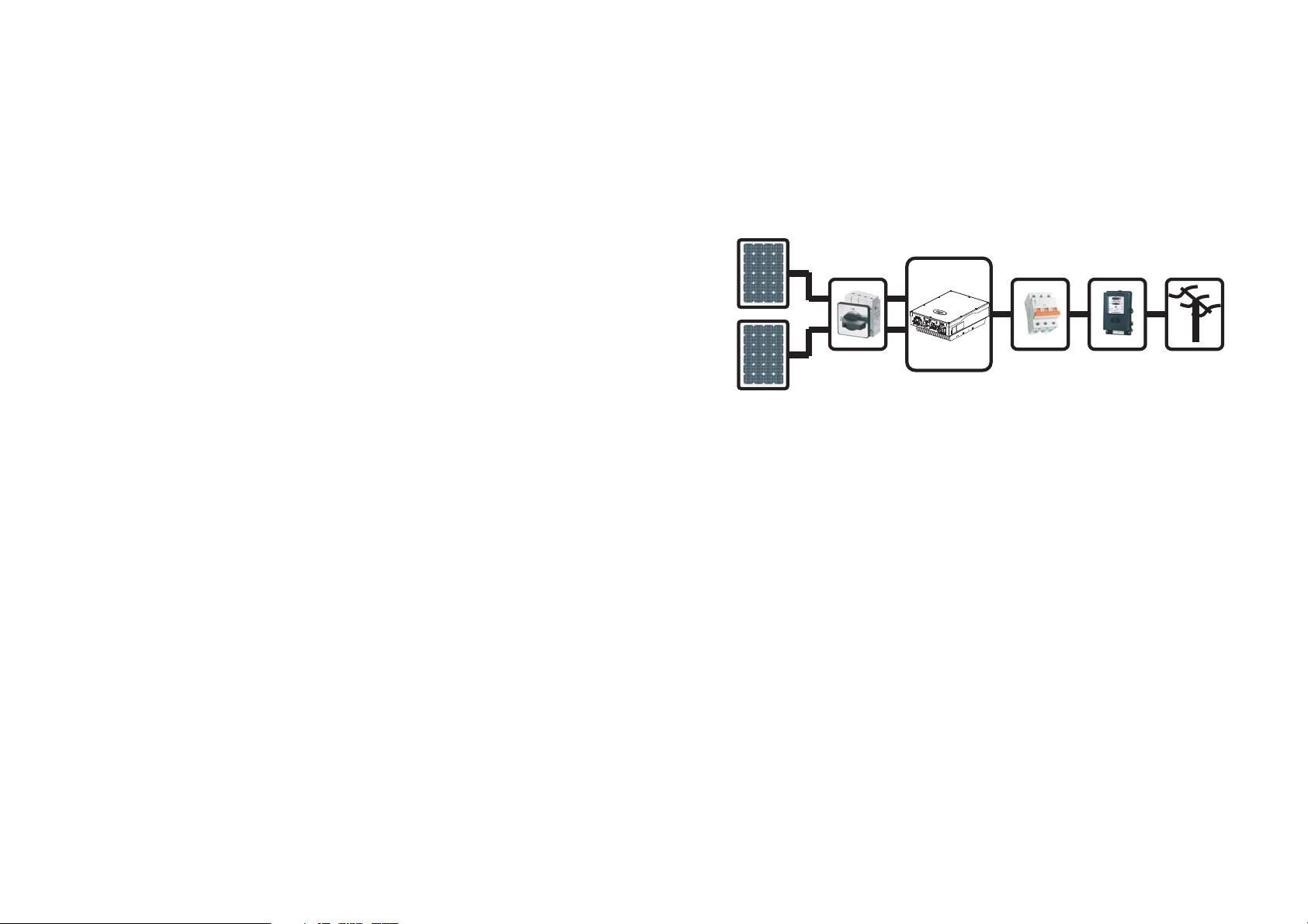
2.1 Intended Use
Growatt UE series inverters are grid-tied inverters which convert DC current
generated by PV modules into AC current and feed it into the public grid in threephase. Growatt UE series inverters are multi-string inverters with multi-MPP trackers,
which mean they are able to connect to different PV module arrays.
Grid-tied PV system Overview:
Input A
DC Switch AC Breaker Energy Meter
Input B
The inverter may only be operated with a permanent connection to the public power
grid. The inverter is not intended for mobile use. Any other or additional use is not
considered as intended use. The manufacturer is not responsible for any damages
resulting from unintended use. Damage caused by such unintended use is at the sole
risk of the operator.
As drawings shown above, a complete Grid-tied PV system consists of PV modules,
PV inverters, public grid and other components. Moreover, PV inverters always act as
key components.
INVERTER
Public Grid
Fig1.1
When design a PV system contains Growatt UE series inverters or any other Growatt
inverters, the system designing software ShineDesign (download from site:
www.ginverter.com) will provide adequate supports.
PV modules Capacitive Discharge Currents
PV modules with large capacities relative to earth, such as thin-film PV modules with
cells on a metallic substrate, may only be used if their coupling capacity does not
exceed 470nF. During feed-in operation, a leakage current flows from the cells to
earth, the size of which depends on the manner in which the PV modules are installed
(e.g. foil on metal roof) and on the weather (rain, snow). This "normal" leakage
current may not exceed 50mA due to the fact that the inverter would otherwise
automatically disconnect from the electricity grid as a protective measure.
3
4
2.2 Safety Precautions
The GROWATT UE series Inverters is designed and tested according to international
safety requirements; however, certain safety precautions must be observed when
installing and operating this inverter. Read and follow all instructions, cautions and
warnings in this installation manual. If questions arise, please contact Growatt's
technical services at +86 755 2747 1942.
2.3 Assembly Warnings
The inverter may only be operated with a permanent connection to
the public power grid. The inverter is not intended for mobile use.
Any other or additional use is not considered the intended use. The
manufacturer/supplier is not liable for damage caused by such
unintended use. Damage caused by such unintended use is at the
WARNING
CAUTION
sole risk of the operator.
Prior to installation, inspect the unit to ensure absence of any
transport or handling damage, which could affect insulation
integrity or safety clearances; failure to do so could result in safety
hazards.
Unauthorized removal of necessary protections, improper use,
incorrect installation and operation may lead to serious safety,
shock hazards or equipment damage.
In order to minimize the potential of a shock hazard due to
hazardous voltages, cover the entire solar array with dark material
prior to connecting the array to any equipment.
Grounding the PV modules: Comply with the local requirements for
grounding the PV modules and the PV generator.
Growatt recommends connecting the generator frame and other
electrically conductive surfaces in a manner which ensures
continuous conduction and ground these in order to have optimal
protection of the system and personnel.
2.4 Electrical Connection Warnings
Some components in the inverter are live. Touching live components
can result in serious injury or death.
Danger to life due to high voltages in the inverter
All work on the inverter may be carried out by qualified
personnel only.
The appliance is not to be used by children or persons with
DANGER
reduced physical, sensory or mental capabilities, or lack of
experience and knowledge, unless they have been given supervision
or instruction.
Children are forbidden to play around the Growatt inverter.
Make all electrical connections (e.g. conductor termination, fuses,
PE connection, etc.) in accordance with prevailing regulations.
When working with the inverter powered on, adhere to all
prevailing safety regulations to minimize risk of accidents.
The Growatt UE series inverters may only be operated with PV
generators (modules and cabling) with protective insulation. Do not
connect any source other than PV modules to the Growatt UE series.
WARNING
CAUTION
Systems with inverters typically require additional control (e.g.,
switches, disconnects) or protective devices (e.g., fuse, circuit
breaker) depending upon the prevailing safety rules.
The Growatt inverter is to be used solely to feed solar energy
converted photovoltaically into the public grid. The inverter is
suitable for mounting indoors and outdoors.
You can use the AC current generated as follows:
Energy flows into the house grid. The consumers connected,
for example, household devices or lighting, consume the
energy. The energy left over is fed into the public grid. When
House
grid:
Public
grid:
the Growatt UE series inverters do not generate any energy,
e.g., at night, the consumers which are connected are supplied
by the public grid. The energy displayed on the LCD of inverter
is for reference only. When energy is fed into the public grid,
the energy meter spins backwards.
Energy is fed directly into the public grid. The Growatt UE
series inverters need install a separate energy meter. The
energy produced is compensated at a rate depending on the
electric power company.
2.5 Operation Warnings
Ensure all covers and doors are closed and secure during operation.
Although designed to meet all safety requirements, some parts and
surfaces of Inverter are still hot during operation. To reduce the risk
of injury, do not touch the heat sink at the back of the PV-Inverter or
nearby surfaces while Inverter is operating.
Incorrect sizing of the PV plant may result in voltages being present
WARNING
which could destroy the inverter. The inverter display will read the
error message “ PV Voltage High ”
Turn the rotary switch of the DC Disconnect to the Off position
immediately.
Contact installer.
5
6
All operations regarding transport, installation and start-up,
including maintenance must be operated by qualified, trained
personnel and in compliance with all prevailing codes and
regulations.
Anytime the inverter has been disconnected from the power
network, use extreme caution as some components can retain
charge sufficient to create a shock hazard; to minimize occurrence
of such conditions, comply with all corresponding safety symbols
and markings present on the unit and in this manual.
In special cases, there may still be interference for the specified
CAUTION
2.6 Symbols on the inverter2.6 Symbols on the inverter
application area despite maintaining standardized emission limit
values (e.g. when sensitive equipment is located at the setup
location or when the setup location is near radio or television
receivers).In this case, the operator is obliged to take proper action
to rectify the situation.
Possible damage to health as a result of the effects of radiation!
Do not stay closer than 20 cm to the inverter for any length of
time.
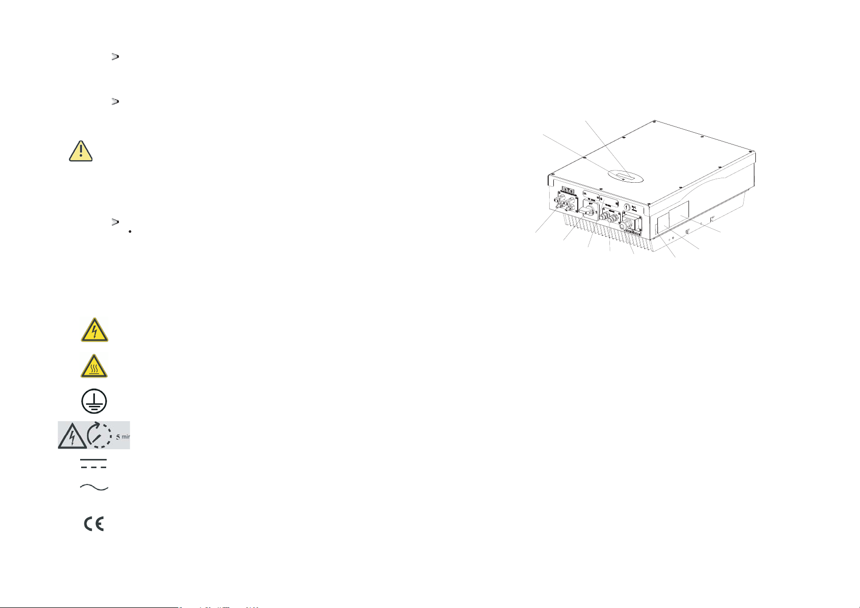
3.1 Growatt UE overview
A
B
C
D
F
Product Description 3Product Description 3
J
G
E
I
H
Symbol Explanation
7
Electrical voltage!
Risk of burns!
Point of connection for grounding protection.
Operation after 5 minutes
Direct Current (DC)
Alternating Current (AC)
CE mark.
The inverter complies with the requirements of the applicable EC
guidelines.
Position
A
B LED
C
D
E
F
G
H
I
J
K
Description
LCD
PV input terminals
Country setting switch
DC switch
Rs232 & DIP switch for RS485 configuration
and External communication accessories power
RS485
AC output
Series Number
Warning label
Type label
8
Symbol Description Explanation
NORMALL
FAULT
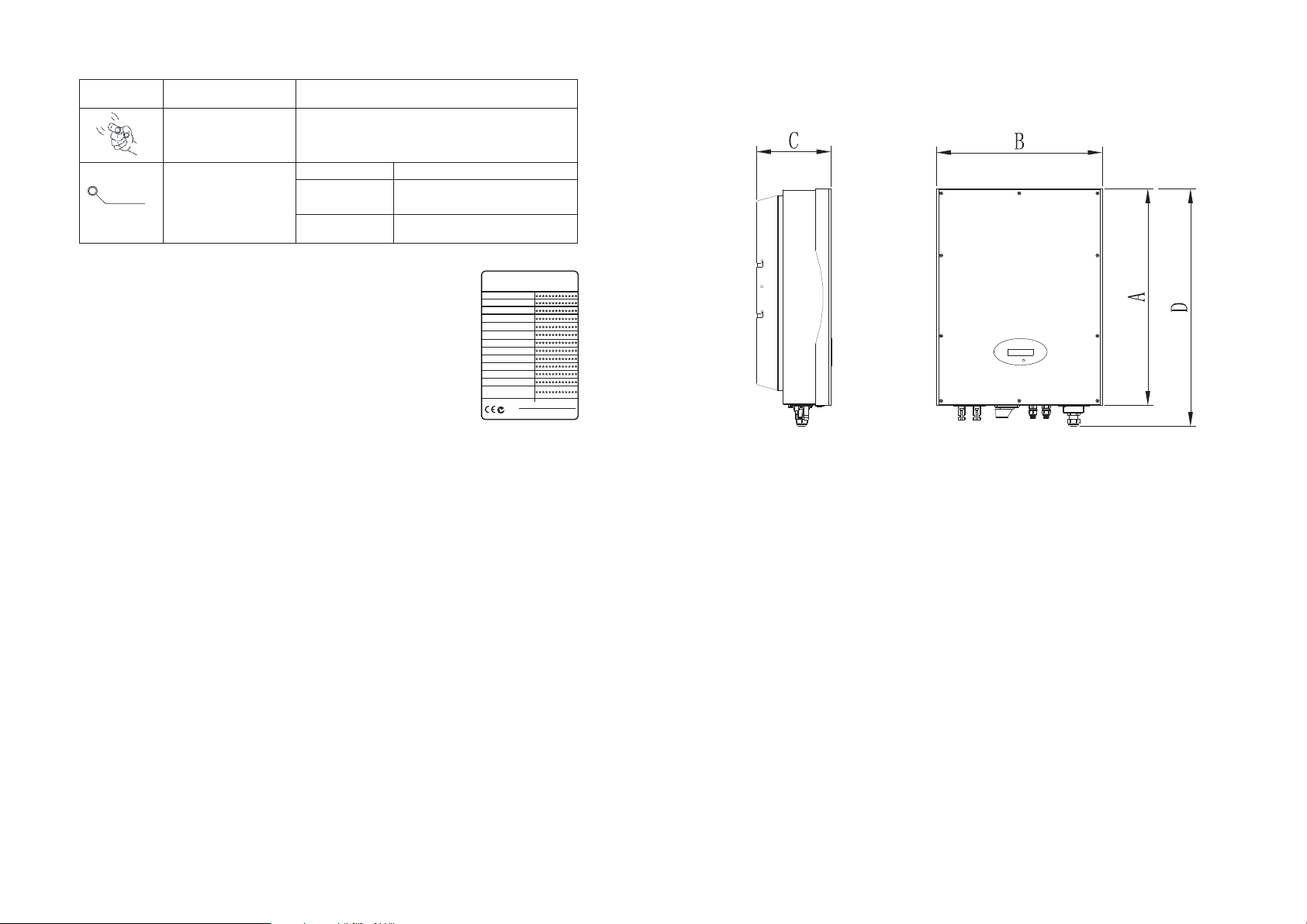
3.3 Size and weight
Tap symbol
Indicates display operation (see Section 6).
Green/constant
1 Fault-- contact installer
Inverter state symbol
Red/constant
Red/flashing
、
2 Standby module
、
1 Fans Fault-- contact installer
、
2 Software update
、
3.2 Type label
The type labels provide a unique identification of the inverter (The
type of product, Device-specific characteristics, Certificates and
approvals). The type labels are on the right-hand side of the
enclosure.
The Certificate Number is just for SAA.
More detail about the type label as the chart below:
Model Name
Max DC voltage
Max input current
PV voltage range
Growatt4000UE
800V 800V 800V
9A / 9A 9A / 9A 10A / 10A
140V-800V 140V-800V 140V-800V
Growatt5000UE Growatt6000UE
Operation
Model Name
Certificate Number
Max.DC Voltage
DC voltage range
Max.input current per string
Max.apparent power
Norminal output current
Norminal output voltage
AC Frequency range
Power Factor
Safety Level
Protection Degree
OperationAmbient
Temperature
GROWATT
PV Grid Inverter
VDE-AR-N4105,AS3100,AS4777
VDE 0126-1-1, IEC 62109
N136
4000 UE
5000-6000 UE
A(mm) B(mm) C(mm) D(mm)
Weight(kg)
566 433 195 620 30
566 433 195 620 32.5
AC Nominal voltage
AC grid frequency;
Nominal AC output power
AC normal output current
Power factor
Environmental Protection
Rating
Operation Ambient
temperature
9
230V 230V 230V
50/60Hz 50/60Hz 50/60Hz
4000W 5000W 6000W
5.8A 7.3A 8.7A
0.9leading- 0.9laging 0.9leading- 0.9laging 0.9leading- 0.9laging
IP65
-25...+60℃
IP65 IP65
-25...+60℃ -25...+60℃
3.4 Transportation
The inverter is thoroughly tested and inspected strictly before delivery. Our inverters leave
our factory in proper electrical and mechanical condition. Special packaging ensures safe
and careful transportation. However, transport damage may still occur. The shipping
company is responsible in such cases. Thoroughly inspect the inverter upon delivery.
Immediately notify the responsible shipping company if you discover any damage to the
packaging which indicates that the inverter may have been damaged or if you discover
any visible damage to the inverter. We will be glad to assist you, if required. When
transporting the inverter, the original or equivalent packaging should to be used, and the
maximum layers for original carton is four, as this ensures safe transport.
10

3.5 Storage of Inverter
If you want to storage the inverter in your warehouse, you should choose an
appropriate location to store the inverter.
The unit must be stored in original package and desiccant must be left in the
package.
The storage temperature should be always between -25 and +60 . And the
storage relative humidity should be always between 0 and 95%.
If there are lots of inverters need to be stored, the maximum layers for original
carton is four.
After long term storage, local installer or service department of GROWATT should
perform a comprehensive test before installation
After long term storage, the Real Time Clock of the inverter
maybe not correct, it will cause the Energy produced today
Information
(E_day) error, you need to set the time and date, refer to 6.3.5
setting inverter time or6.4.3 text line d setting date and time) .
℃℃
3.6 The advantage of the Growatt UE inverters3.6 The advantage of the Growatt UE inverters
Unpacking 4Unpacking 4
Before opening the packing box of Growatt UE, please note that whether there are
any visible external damages.
Once open the packing box, please check the delivery for completeness and for any
visible external damages of the inverter. If there are anything damaged or missing,
please contact your dealer. Complete delivery should contain as follows.
The features of UE inverter are below:
Dual independent MPP trackers
Integrated DC disconnect switch
Bluetooth/ RF technology/ Zigbee/ Wifi
Wide PV voltage range 140V~800V
The maximum efficiency is 97.8%
IP65 environmental protection
Easy to install
11
Item
A1
B1
:
C
D1
E1
F4
G
H*
I**
--
--
***For type 1 RS485
For type 2 RS485
Information
Number Description
Inverter
Mounting frame
3
3
2
2
1
1
Though the packaging box of Growatt UE is durable, please
treat the packing box gently and avoid dispose the packing box.
Expansion bolt
Shell
Cable gland for AC connection
M4 cross recessed countersunk head screws
M6 socket head cap screws
RS 485 PLUG
RJ 45 PLUG
Warranty(not show in the picture)
User manual (not show in the picture)
12
Installation5 Installation5
5.1 Safety instruction
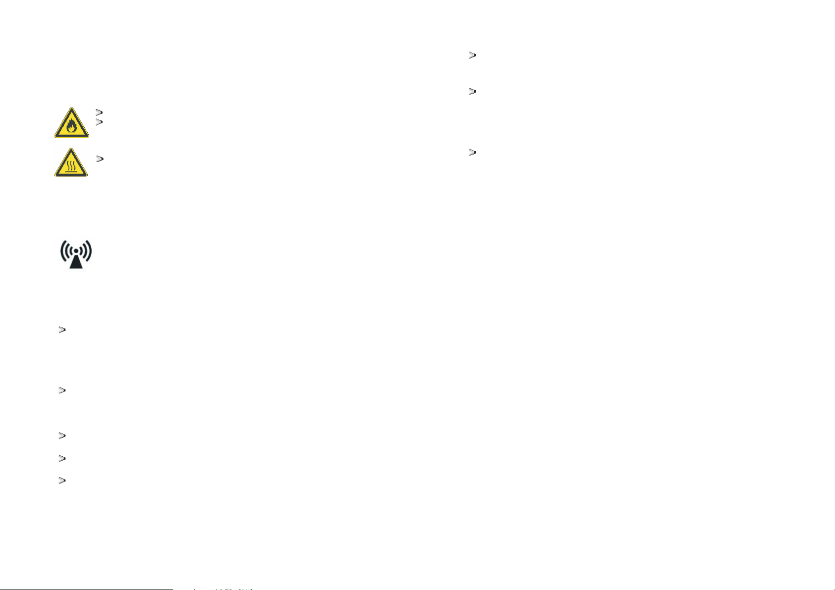
Danger to life due to fire or explosion
Despite careful construction, electrical devices can cause fires.
Do not install the inverter on easily flammable materials and where
flammable materials are stored.
Risk of burns due to hot enclosure parts
Mount the inverter in such a way that it cannot be touched
inadvertently.
Possible damage to health as a result of the effects of radiation!
In special cases, there may still be interference for the specified application
area despite maintaining standardized emission limit values (e.g. when
sensitive equipment is located at the setup location or when the setup
location is near radio or television receivers).In this case, the operator is
obliged to take proper action to rectify the situation.
Never install the inverter near the sensitive equipment e.g. Radios,
telephone, television, etc
Do not stay closer than 20 cm to the inverter for any length of time unless it
is absolutely necessary.
Growatt assumes no responsibility for compliance to EMC regulations for
the complete system
)
All electrical installations shall be done in accordance with the local and
national electrical codes. Do not remove the casing. Inverter contains no
user serviceable parts. Refer servicing to qualified service personnel. All
wiring and electrical installation should be conducted by a qualified
service personnel.
Carefully remove the unit from its packaging and inspect for external
damage. If you find any imperfections, please contact your local dealer.
Be sure that the inverters connect to the ground in order to protect
property and personal safety.
The inverter must only be operated with PV generator. Do not connect
any other source to it.
Both AC and DC voltage sources are terminated inside the PV Inverter.
Please disconnect these circuits before servicing.
This unit is designed to feed power to the public power grid (utility) only.
Do not connect this unit to an AC source or generator. Connecting
Inverter to external devices could result in serious damage to your
equipment.
(
When a photovoltaic panel is exposed to light, it generates a DC voltage.
When connected to this equipment, a photovoltaic panel will charge the
DC link capacitors.
Energy stored in this equipment's DC link capacitors presents a risk of
electric shock. Even after the unit is disconnected from the grid and
photovoltaic panels, high voltages may still exist inside the PV-Inverter.
Do not remove the casing until at least 5 minutes after disconnecting all
power sources.
Although designed to meet all safety requirements, some parts and
surfaces of Inverter are still hot during operation. To reduce the risk of
injury, do not touch the heat sink at the back of the PV-Inverter or nearby
surfaces while Inverter is operating.
5.2 Selecting the Installation Location
This is guidance for installer to choose a suitable installation
location, to avoid potential damages to device and operators.
1) The wall selected to install the inverter must be strong and firm
enough to support and bear the weight of the inverter for a long
period time. (Refer to Chapter 11 Specifications)
2) The location selected must be suitable for inverters' dimension. (Refer
to 3.3 Dimensions and Fig.5.2 Required Clearances)
3) Do not install the inverter on structures constructed of flammable or
thermo labile materials.
4) Never install the inverter in environment of little or no air flow, nor
dust environment.
5) The Ingress Protection rate is IP65 which means the inverter can be
installed outdoors and indoors.
6) Do not expose the inverter to direct sunlight, in order to avoid the
power and efficiency derating caused by excessive heating.
7) The humidity of the installation location should be 0~95% without
condensation.
8) The ambient temperature of the inverter should be -25 ~+60
9) The installation location must be freely and safely to get at all times.
10) Vertically installation and make sure the connection of inverter must
be downwards. Never install horizontal and avoids forward and
sideways tilt.( Refer to drawings below)
℃℃.
13
14
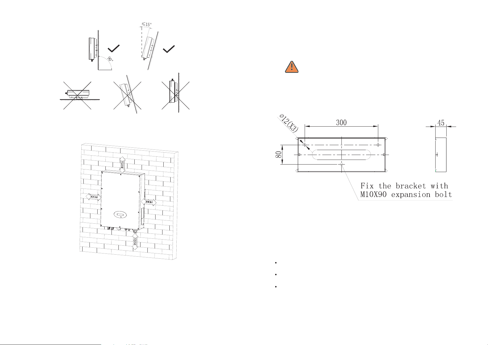
Fig5.1
11) Notice the minimum clearances of the inverter. (Refer to 3.3 Dimensions
and Fig.5.2 Required Clearances).
5.3 Installation guide
5.3.1 Mounting the Bracket
In order to avoid electrical shock or other injury, inspect existing
DANGER
To mount the inverter on the wall, we should mount the bracket to the wall
firmly first of all.
electronic or plumbing installations before drilling holes.
Fig5.2
12) Do not install the inverter near television antenna or any other antennas
and antenna cables.
13) Do not install the inverter in living area, the noise caused by the
machine may affect on daily life.
14) For security reasons, don't install the inverter in place where the
children can reach.
15
Bracket of Growatt 4000UE-6000UE
Fig5.3
Hint: Data units in mm
Steps:
Use the bracket as a drilling template and mark the positions where you need to
drill holes.
Drill three holes for screws, fasten the bracket against the wall with expansion
bolts.
Fix the mounting frame on the wall as the figures shown below, combine as the
screws as the Items Fig 4.1 shows (items C)
16
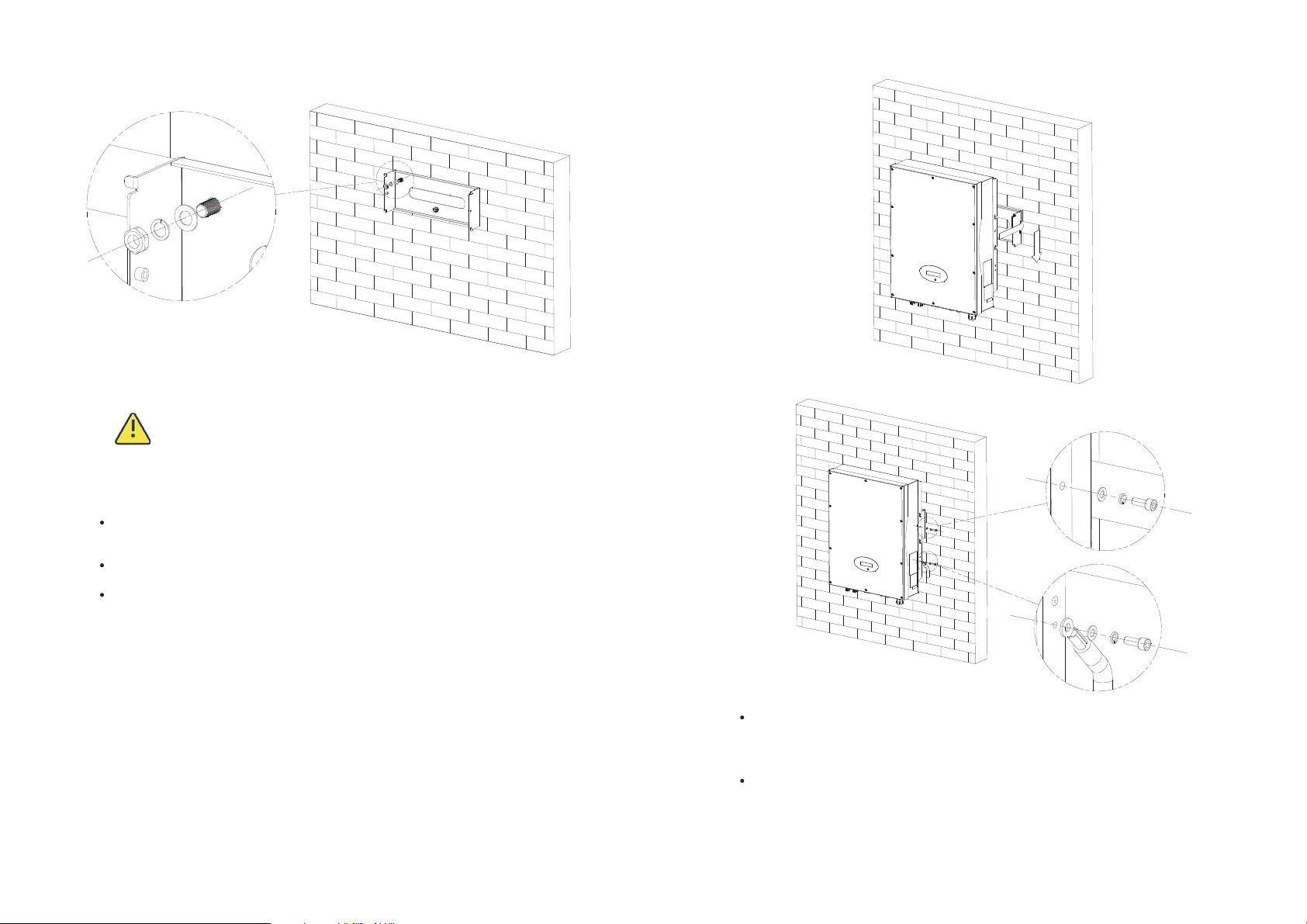
5.3.2 Mounting Inverter5.3.2 Mounting Inverter
Falling equipment can cause serious or even fatal injury, never
mount the inverter on the bracket unless you are sure that the
WARNING
After the bracket is firmly mounted on the wall, then mount the inverter on the
bracket.
Rise up the Growatt UE a little higher than the bracket. Considering the weight of
Growatt UE, you need to hang on the inverter. During the process please maintain
the balance of the Growatt UE.
Hang the inverter on the bracket through the match hooks on bracket and the
back of the inverter.
After confirming the inverter is fixed reliably, fasten two M6 soket head cap
screws on the left and right side firmly to prevent the inverter from being lifted
off from the bracket.
mounting frame is really firmly mounted on the wall after carefully
checking.
Connecting a Second Protective Conductor
if it is requirement, the earth terminal can be used to connect a second protective
conductor or as equipotential bonding. This prevents touch current if the original
protective conductor fails.
Recommend awning installation, the purpose is to extend the inverter service life
and reduce the power derating of the inverter. The dimension of the awning, refer
to Fig 5.6.
17
18
 Loading...