

Growatt 2000HF, 2500HF, 3000HF Installation & Operation Manual
Installation
&
Operation Manual
GROWATT NEW ENERGY CO., LTD
No.12 Building, Xicheng Industrial
Zone, Bao’an District, Shenzhen, P. R.China
+ 86 755 2747 1900
+ 86 755 2749 1460
service@ginverter.com
www.ginverter.com
T
F
E
W
GR - UM - 006 - 03
Growatt 2000HF
Growatt 2500HF
Growatt 3000HF
Introduction
1.1 Validity
1.2 Target Group
1.3 Produ ct Overview
Unpacking
2.1 Unpacking and In spection
Mounting
3.1 Selecting Moun ting Location
3.2 Dimensions and R equired Cl earances
3.3 Mounting the Bra cket
3.4 Mounting Growatt HF
Electrical Connections
4.1 Wiring AC Ou tput
4.2 Wiring DC In put
Directory
1
2
3
4
2.2 Information of L abel
1.4 Safety
Commissioning
5
Growatt HF series inverters are gri d-tied inverters whi ch convert DC cur rent
generated by PV mo dules into AC c urrent a nd feed it into the public grid in singlephase. Growa tt HF in verters are multi-string inver ters with high frequency
transformer for ga lvanic isolation, with the specially design ed i ntegrated high
frequen cy tra nsformer and wide input voltage range Growatt HF are able to be
connected to different pane ls ( e.g. monocrystal, polyc rystal s ilicon panels and thinfilm panels).
Introduction 1
1.1 Validity
1.2 Target Group
1.3 Product Overview
This install ation guide contains installation, commissio ning, communi cation, trouble
shooting and information of Growatt HF seri es inverters:
Growatt 2000 HF
Growatt 2500 HF
Growatt 3000 HF
This manual is for qualif ied personnel who hav e rec eived training an d have
demonstrated skills and knowledge in the co nstruction and operat ion of this device.
Qualified Personnel are trained to deal with the danger s and haza rds involve d in
installing elect ric devices.
Contact
Display and Messages
7.1 LCD display
7.2 LCD control
7.3 Setting of the LCD d isplay
8.1 ShineNet
8.2 ShineVision
8.3 ShineWebBox
Communications
9.1 General questi on
9.2 Error M essages displayed o n LCD
Trouble Shooting
Specifications
Growatt Factory
Warranty
7
8
9
10
11
12
With this ins tallation guide, users are able to install and operate the Growatt HF
inverters easily. This manual does n ot cover any detai ls concernin g about equipment
connected to the Growatt HF. Sto re thi s manual where accessible a t all times.
Notes
respons ibilities to inform t he users.
: For possible chang es in this manual, Growatt New Ener gy Co., Ltd accepts no
1
Operation Modes
6.2 Normal Mode
6.4 Shutdown Mode
6.3 Fault Mode
6.1 Wiring Mod e
6
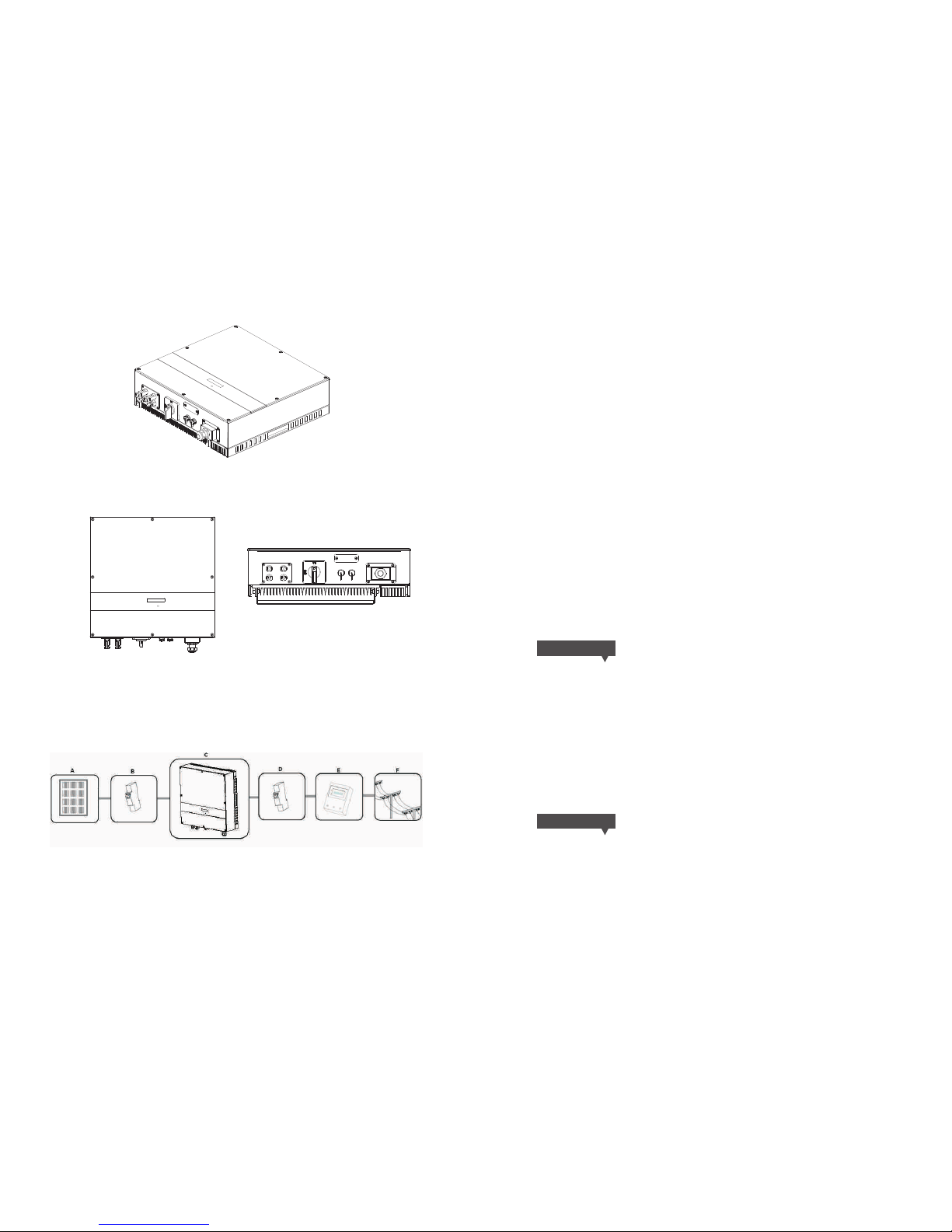
Inverters Overview:
Front and Bottom Overview:
Fig 1.1
Fig 1.2
Notes: Growatt HF for Australi a won’t be equipped with DC swi tch
Grid-tied PV System Overview:
As drawings shown above, a complete g rid-tied PV system consists of PV m odules, PV
inverters, publi c grid and other compon ents. Moreover, PV inverters a lways act as key
components.
Fig 1.3
The Growatt HF inverters may only be oper ated with PV generators (modules a nd
cabling) with protective insulatio n. D on't connect any sources of energy other than
PV modules to the Growatt HF inver ters.
When your PV sys tem contains Growa tt HF inv erters o r any oth er Growatt inverters,
the PV sys tem design software ShineDesign w ill provide adequa te supp orts.
(Download link: ww w.ginverter.co m)
Notes
range, Growatt HF is v ery suitable for thin-film sys tems or any other PV systems tha t
requires NEGATIVE GR OUND or GALVAN IC ISOLATION.
: Because of the high frequenc y transform er isolation and wide input voltage
1.4 Safety
Growatt HF is designed for global consum ers, and is in acc orda nce with most of t he
safety standards of various co untries and regions.
VDE 0126 -1-1 , AS47 77, ETL, FC C, CE
Appropriate Usage:
Danger t o life d ue to hi gh voltag es in th e inve rter!
All work on the invert er may be carried out by qu alified personnel o nly.
The appl iance is not to b e used by ch ildren or persons with re duced phy sical, se nsory
or mental capabilities , or lack of experience and know ledge, unless they have been
given supervisio n or instruction.
Childre n should be supervise d to ensure that they do not play w ith the appliance
Danger o f burn i njur ies due to ho t encl osur e parts!
During opera tion, the u pper lid of the en closure and the enclosure body may become
hot.
Only touch the lower e nclosure l id during operation .
DANGER!
CAUTION!
2
3
Unpacking 2
2.1 Unpacking and Inspection
Notes
box softly and avoid d isposing the packin g box.
: Though the packagin g box of Growatt HF is du rable, please treat th e packing
Before opening the pack ing box of Growatt H F, please note that whethe r there are
any visible external damages.
Once open the packing box, p lease ch eck the delivery for c ompleteness and for any
visible ex ternal damages of t he inverter. If t here are anything da maged or missing,
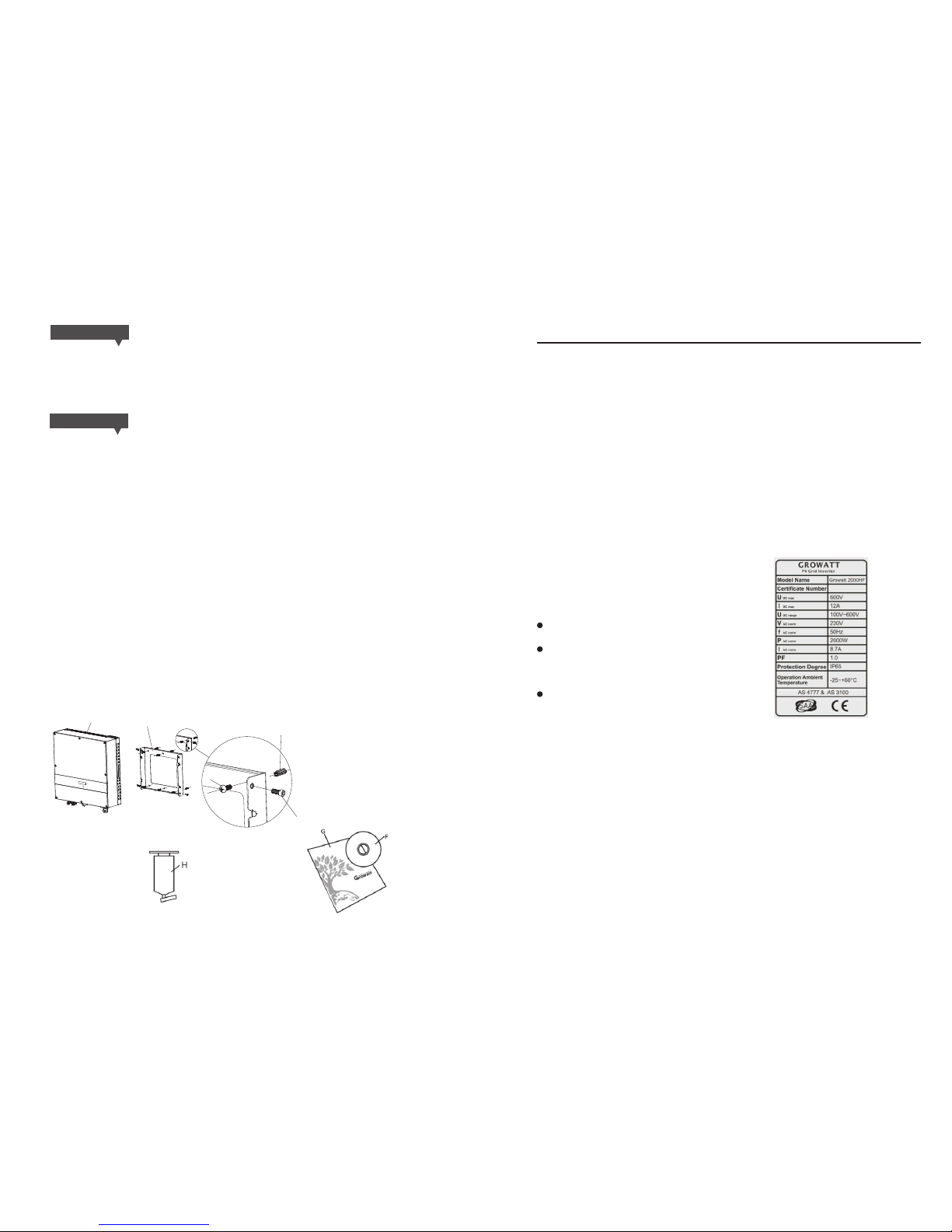
please contact you r dealer. Complet e delivery should con tain items as follow:
Item
A
B
C
D
E
F,G
Number
1
1
4
6
6
1
Descri ptio n
Growat t HF inv erte r
Mounti ng fra me
Mounti ng scr ews
Safety -loc k scre ws
Mounti ng fra me scr ew sleeve s
Instal lati on & Ope ration Ma nual
H(Opti onal )
1( Optiona l)
Blueto oth
2.2 Information of Label
The label contains i nformation as below :
The inverter type/ model (Model Name);
The certificates a nd approva ls (Certificate
Number and Logos at th e bottom of the
label);
Specifications o f the inverter (From UD Cmax
to Operation Ambie nt Temperature).
3Mounting
3.1 Selecting Mounting Location
This is guidance for i nstaller to choose a su itable installati on location, to avoid
potential damage s to devices and operat ors.
Fig 2.1
Fig 2.2
4 5
Possib le dam age th e PV module s as a res ult of I dentifi cati on of St ring Fail ure!
The Growatt HF In verter i s equipp ed w ith a system which recogni zes tota l fa ilure of
individual strin gs or part-strings.
CAUTION!
B
D
E
C
A
Possib le dam age to h ealth as a re sult o f the ef fect s of rad iation!
Do not stay closer tha n 20 cm to the inverter for a ny length of time.
CAUTION!
F
G
H
I
J
The wall se lect ed to inst all the in vert er must be st rong an d firm
enough to supp ort and bear the weig ht of the inverter for a lo ng
period t ime. ( Refe r to Chapte r 10 Spe cifi cations )
The l ocat ion sele cted mus t be suit able for dim ensions of Grow att
HF. (Re fer to 3 .2 Dimens ions a nd Req uired Cle aran ces)
Do not inst all the inve rter on stru ctur es cons truc ted of f lamm able
or therm olab ile ma terials .
never i nstall the i nverter in en viro nment of lit tle or n o ai r fl ow, o r
enviro nmen t of d ust . T hat may der ate t he ef fici ency o f heat
dissip atio n, whi ch will der ate th e conv ersion eff iciency o f inve rter s.
The In gress Prot ecti on rate (IP level) is IP65 which means G rowatt
HF can be in stal led bo th indoor s and ou tdoo rs.
Do not expo se the in verter t o di rect sunl ight , in order to avoi d the
power an d efficien cy der atin g caused by e xces sive h eating.
The humidit y of l ocat ion s hould be wit hin 0 ~95% and withou t
conden sati on.
K
L
M
The ambi ent te mper ature of th e inve rter s hould be -2 5℃~+60℃.
The ins tall atio n locati on mu st be fre ely a nd safel y to g et fo r
operat ors or e lect ricians a t all ti mes.
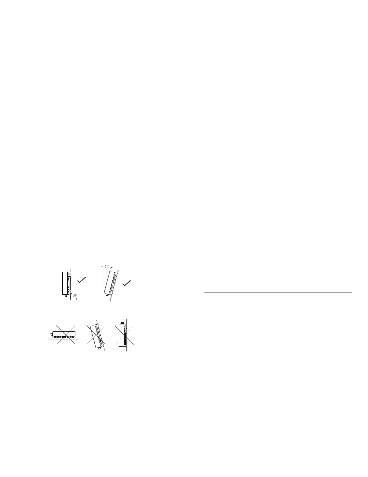
Ver tica lly inst alla tion and m ake s ure the c onnecti on of inverter is
downwa rd. Never in stall horiz onta l an d av oids forwar d and
sidewa ys til t, ref er to drawi ng bel ow.
Notice th e minim um c lear ances o f th e in vert er. ( Refe r to 3 .2
Dimens ions a nd Req uired Cle aran ces)
Do not in stal l Growatt HF nea r televis ion ant enna or any othe r
antenn as and a ntenna ca bles , f or possib le int erf eren ces of
invert er or ca bles .
Do n ot insta ll Gr owat t HF i n liv ing a rea, the noise cause d by
invert er mig ht aff ect on d aily l ife.
For secu rity r easons, D O NOT insta ll Gro watt HF in pl ace where t he
childr en can r each .
N
3.2 Dimensions and Required Clearances
Dimensions and wei ght :
Type s
Height (H) Width( W)
Wei ght/ kg
2000HF
2500HF
3000HF
452
452
452
450
450
450
17.06
17.06
17.06
Depth( D)
However, a dditional clearance s are required to guarantee runn ing and operation of
Growatt HF inverters. Especially when several inverters are installed together, the
clearances betwe en inverters and obje cts are nece ssary.
130
130
130
Fig 3.1
6
7
Table 3.1
E
C
D
A
B
 Loading...