

Growatt 8000TL3-S, 7000TL3-S, 11000TL3-S, 12000TL3, 12000TL3-S Installation & Operation Manual
...Page 1
GR - UM -140-A- 00
Growatt 10000TL3-S
Growatt 12000TL3-S
Growatt 9000TL3-S
Growatt 12000TL3
Growatt 8000TL3-S
Growatt 7000TL3-S
Growatt 11000TL3-S
Growatt 13000TL3-S
Growatt 15000TL3-S
Installation
&
Operation Manual
Shenzhen Growatt New Energy Technology CO.,LTD
No.28 Guangming Road, Longteng Community,
Shiyan, Bao'an District, Shenzhen, P.R.China
+ 86 755 747 1942
service@ginverter.com
www.ginverter.com
T
E
W
Page 2

Info rmation on t his Manual
1.1Documents use
1.2 Symbols Used
1.3 Glossary
Safe ty
2.1 Intended Use
Prod uct Descri ption
3.1 Inverter overview
3.2 Type label
3.3 Size and weight
3.4 Tran sp or ta ti on
Unpa cking
Index
1
2
3
4
2.2 Safety Prec au ti on s
Inst allation
5
5.1 Safety instruction
5.2 Selecting the Installation Location
2.3 Assembly Wa rn in gs
2.4 Electrical Connection War ni ng s
2.5 Operation War ni ng s
2.6 Symbols on the inverter
3.5 Storage of Inverter
3.6 The a dvant age of th e inver ter
5.3 Installation guide
5.4 Electrical Connections
5.5 Grid Type
Page 3
Star t-Up and shu t down
the in verter
7
7.1 Start-Up the inverter
7.2 Shut down the Inverter
Comm issionin g
6
6.1 Commission the Inverter
6.2 Operation Modes
6.3 Country Setting and LCD Display
6.4 Do uble MP PT of the TL3-S
6.5 Communication
Main tenance an d Cleaning
8
8.1 Cleaning the Inverter
8.2 Checking the DC Disconnect
Trouble s hoo ting
9
10.1 Dismantling the Inverter
10.2 Packing the Inverter
Deco mmission ing
10
10.3 Disposing of the Inverter
Spec ificatio n
11
Cert ificates
PV sys tem instal lation
12
13
11 .1 Specification of TL3-S
11.2 DC connector info
11 .3 Torqu e Val ue s
11.4 Spare Pa rt s an d Ac ce ss or ie s
Cont act
14
9.1 Error M es sa ge s di sp la ye d on L CD
9.2 System fault
9.3 Inverter war ni ng
9.4 Inverter fault
12.1 Single inverter
12.2 Multi inverters
Page 4
Store this manu al where it w il l be accessible at all ti me s. We as su me no l ia bi li ty for
any d am ag e c au se d by fa il ur e t o ob se rv e t he se inst ru ct io ns . F or poss ib le ch an ge s in
this ma nu al , S HE NZ HE N G RO WATT NE W ENERGY TE CH NO LO GY CO ., LTD accepts n o
res po ns ib il it ie s to i nf or m th e us er s.
Information on this Manual1
1.1 Do cuments us e
1.1. 2 Tar get G roup
1.1. 3 Storage of t he manual
This i ns ta ll at io n gu id e contains in st al la ti on , co mm is si on in g, communication, t rouble
shooting. In fo rm at io n of Gro wa tt TL3-S se ri es i nv er te rs :
This manual is for qualified persons who will operate, maintenance, service and
rep ai re d in ve rt er s.
Wi th th is in st al la ti on gu id e, us er s are ab le to install a nd op er at e t he in ve rt er s e as il y.
This ma nu al d oe s not c ov er any de ta il s co nc er ni ng e qu ip me nt co nn ec te d to the
inverter. St ore this manual where a cc es si bl e at a ll t im es .
1.1. 1 Vali dity
WAR NI NG
CAUTION
NOTICE
Informat io n
WAR NI NG i nd ic at es a h az ard ou s si tu at io n wh ic h, i f no t av oi de d,
could res ul t in d ea th o r se ri ou s in ju ry.
WAR NI NG i nd ic at es a h az ard ou s si tu at io n wh ic h, i f no t av oi de d,
could res ul t in d ea th o r se ri ou s in ju ry.
NOTICE indicates a situation which, if not avoided, could res ul t
in prop er ty d am ag e.
Information that you must rea d an d kn ow t o en su re o pt im al
operation of the system.
1
2
1.2 Sy mbols Used
The following types of safety instructions and general information appear in this
document as described below:
Symb ol Desc ription
Read t he manual
DANGER
DANGER indicates a hazard ou s si tu at io n wh ic h, i f no t av oi de d,
will re su lt i n de at h or s er io us i nj ur y.
Gro wa tt 7000TL3-S
Gro wa tt 8000TL3-S
Gro wa tt 9000TL3-S
Gro wa tt 10000TL3-S
Gro wa tt 11000TL3-S
Gro wa tt 12000TL3
Gro wa tt 12000TL3-S
Gro wa tt 13000TL3-S
Gro wa tt 15000TL3-S
1.1. 4 Addition al Informa tion
For further information on special topics in the download are a at w ww. gi nv er te r.com
1.3 Gl ossary
AC
Abbre vi at io n fo r "A lt er nating Curre nt "
DC
Abbre vi at io n fo r "D ir ec t Cu rrent"
Ener gy
Energy is measure d in W h (w at t ho ur s) , kW h (k il ow at t ho ur s) o r MW h (m eg aw at t
hours).
Page 5
Safety 2
2.1 In tended Use
TL3-S series inverters are gr id -t ie d in ve rt er s wh ic h co nv er t DC c ur re nt g en er at ed b y
PV modules into AC curren t an d fe ed i t in to t he p ub li c gr id i n th re e- ph as e. T L3 -S
series inverters are mu lt i- st ri ng i nv er te rs w it h mu lt i- MP P tr ac ke rs , wh ic h me an t he y
are a bl e to c on ne ct t o di ff erent PV module arrays.
The inverter may only be operated with a permanent connection to the public power
grid. The inverter is not intended for mobile use. Any other or additional use is not
considere d as i nt en de d us e. T he m an uf ac tu re r/ su pp li er i s no t responsible for any
damages res ul ti ng f ro m un in te nd ed u se . Da ma ge c au se d by s uc h un in te nd ed u se i s
at the sole risk of the operator.
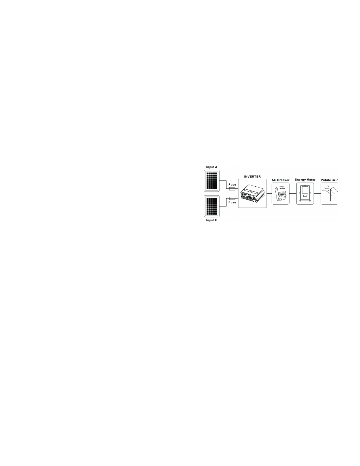
As drawings shown above, a complete Grid-tied PV system consists of PV modules,
DC fuse or brea ke r (o nl y fo r Fr an ce , th e ot he r co un tr y is o pt io na l) , PV i nv er te rs ,
public grid and other components. Moreo ve r, PV inverters always act as key
components.
PV mod ul es C apaci ti ve Disc ha rg e Curre nt s
PV modules with large capacities re la ti ve t o ea rt h, s uc h as t hi n- fi lm P V mo du le s wi th
cells on a metallic substrate, may only be used if their coupling capacity does not
exceed 2.2uF. Dur in g fe ed -i n op er at io n, a l ea ka ge c ur re nt f lo ws f rom the cells to
earth, the size of which depends on the manner in which the PV modules are in st al le d
(e.g. foil on metal roo f) a nd o n th e we at he r (r ai n, s no w) . Th is " no rm al " le ak ag e
curre nt m ay n ot e xc ee d 10 0m A du e to t he f ac t th at t he i nv er te r wo ul d ot he rw is e
automatically disconnect from t he e le ct ri ci ty g ri d as a p ro te ct iv e me as ure.
3
4
Grid-tied PV system Overview:
Fig1.1
When design a PV system contains any Grow at t in ve rt er s, t he s ys te m de si gn in g
software “S hi ne De si gn ” (d ow nl oa d fr om s it e: w ww. gi nv er te r.co m) w il l pr ov id e
adequate supports.
Power is measured i n W (w at ts ), k W (k il ow at ts ) or M W (m eg aw at ts ). P ow er i s an
instantaneous value. It displays the power your inverter is curre nt ly f ee di ng i nt o th e
power distribution grid.
Powe r rate
Power rate is the radio of curren t po we r fe ed in g in to t he p ow er d is tr ib ut io n gr id a nd
the maximum power of the inverter that can feed into the power distribution grid.
Powe r Factor
Power factor is the ratio of true power or watts to apparen t po we r.
PV
Abbre vi at io n fo r ph ot ov ol ta ic
Wire less commu nication a ccessori es (option al)
The extern al w ireless communication technology is a radio technology that allows
the inverter and other communication prod uc ts t o co mm un ic at e wi th e ac h ot he r.
Powe r
Page 6
WAR NI NG
Make all electrical connections (e.g. conductor termination, fuses,
PE connection, etc.) in accorda nc e wi th p re va il in g regulations.
When working with the inverter powere d on , ad he re t o al l
pre va il in g sa fe ty r eg ul at io ns t o mi ni mi ze r is k of a cc id en ts .
The inverter may only be operated with PV generators (modules and
cabling) with pro te ct iv e in su la ti on . Do n ot c on ne ct a ny s ou rc e ot he r
than PV modules to the inverter.
Systems with inverters typically re qu ir e ad di ti on al c on trol (e.g.,
switches, disconnects) or pro te ct iv e de vi ce s (e .g ., f us e, c ir cu it
bre ak er ) de pe nd in g up on t he p re va il in g sa fe ty r ul es .
CAUTION
House
grid:
Public
grid:
Energy flows into the house grid. The consumers connected,
for example, household devices or lighting, consume the
energy. Th e en er gy l ef t ov er i s fe d in to t he p ub li c gr id . Wh en
the UE series inverters do not generate any energy, e. g. , at
night, the consumers which are co nn ec te d ar e su pp li ed b y th e
public grid. The energy displayed on the LCD of inverter is for
ref er en ce o nl y. Whe n en er gy i s fe d in to t he p ub li c gr id , th e
energy meter spins backward s.
Energy is fed direc tl y in to t he p ub li c gr id . Th e UE s er ie s
inverters need install a separate energy meter. Th e en er gy
pro du ce d is c om pe ns at ed a t a ra te d ep en di ng o n th e el ec tr ic
power company.
2.5 Op eration Warn ing s
WAR NI NG
Ensure al l co ve rs a nd d oo rs a re c lo se d an d se cu re during operation.
Although designed to meet all safety re qu ir em en ts , so me p ar ts a nd
surfaces of Inverter are st il l ho t du ri ng o pe ra ti on . To red uc e th e ri sk
of injury, do no t to uc h th e he at s in k at t he b ac k of t he P V-I nv er te r or
nearby surfaces while Inverter is operating.
Incorre ct s iz in g of t he P V pl an t ma y re su lt i n vo lt ag es b ei ng p resent
which could destroy t he i nv er te r.
Turn t he r ot ar y sw it ch o f th e DC D is co nn ec t to t he O ff position ;
immediately.
Contact installer.
The Gro wa tt i nv er te r is t o be u se d so le ly t o fe ed s ol ar e ne rg y
converted photovoltaically into the public grid. The inverter is
suitable for mounting indoors and outdoors.
You ca n us e th e AC c ur rent generated as follows:
5
6
2.2 Sa fety Preca utions
The TL3-S series Inverter is designed and tested accord in g to I nt er nalational safety
req ui re me nt s; h ow ev er, ce rt ai n sa fe ty p re ca ut io ns m us t be o bs er ve d wh en i ns ta ll in g
and operating this inverter. Rea d an d fo ll ow a ll i ns tr uc ti on s, c au ti on s an d wa rn in gs
in this installation manual. If questions arise, please contact our technical services at
+86 (0)755 2747 1942.
2.3 As sembly Warni ngs
CAUTION
WAR NI NG
The inverter may only be operated with a permanent connection to
the public power grid. The inverter is not intended for mobile use.
Any other or additional use is not considered t he i nt en de d us e. T he
manufacture r/ su pp li er i s no t li ab le f or d am ag e ca us ed b y su ch
unintended use. Damage caused by such unintended use is at the
sole risk of the operator.
Prior to installation, inspect the unit to ensure a bs en ce o f an y
transport or handling damage, which could aff ec t in su la ti on
integrity or safety clearances; failure t o do s o co ul d re su lt i n sa fe ty
hazards .
Unauthorized re mo va l of n ec es sa ry p ro te ct io ns , im proper use,
incorre ct i ns ta ll at io n an d op er at io n ma y le ad t o se ri ou s sa fe ty,
shock hazards o r eq ui pm en t da ma ge .
In orde r to m in im iz e th e po te nt ia l of a s ho ck h az ar d du e to
hazardo us v ol ta ge s, c ov er t he e nt ir e so la r ar ra y wi th d ar k ma te ri al
prior to connecting the array to any equipment.
Gro un di ng t he P V mo du le s: C om pl y wi th t he l oc al r eq ui rements for
gro un di ng t he P V mo du le s an d th e PV g en er at or.
We re co mm en d co nn ec ti ng t he g en er at or f ra me a nd o th er
electrically conductive surfaces in a manner which ensure s
continuous conduction and gro un d th es e in o rd er t o ha ve o pt im al
pro te ct io n of t he s ys te m an d pe rs on ne l.
2.4 El ectrical C onnectio n Wa rni ngs
DANGER
Some components in the inverter are l iv e. Tou ch in g li ve c om po ne nt s
can res ul t in s er io us i nj ur y or d ea th .
Danger to life due to high voltages in the inverter
All work on the inverter may be carried out by qualified
personnel only.
The appliance is not to be used by children o r pe rs on s wi th
red uc ed p hy si ca l, s en so ry o r me nt al c ap ab il it ie s, o r la ck o f
experience and knowledge, unless they have been given supervision
or instruction.
Childre n ar e fo rb id de n to p la y around the inverter.
Page 7
Product Description 3
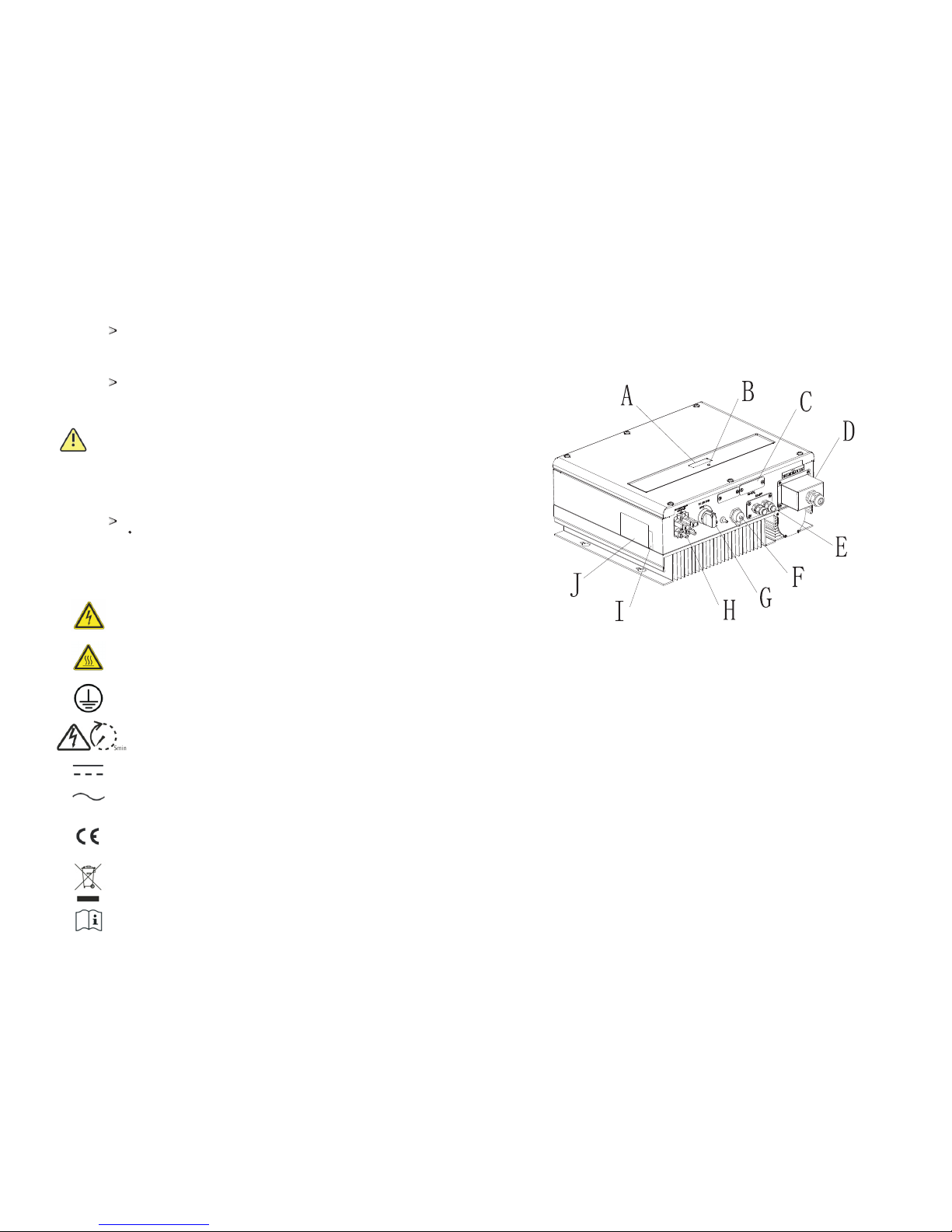
3.1 In verter ove rview
Position
Descript io n
7
8
A
LCD
B LED
C
Rs232 & DIP sw it ch f or R S4 85 c on fi gu ration
and Extern al c om mu ni cation acce ss or ie s po we r
D
AC output
E
RS 485
F
DRM PORT (O nl y fo r Au st ra li a)
G
DC switch
H*
PV input ter mi na ls
I
Series Num be r
J
Type label
* 7000-11000TL3-S & 12000TL3 2 pairs,12000-15000TL3-S 3 pairs.
All operations re ga rd in g tr an sp or t, i ns ta ll at io n an d st ar t- up ,
including maintenance must be operated by qualified, trained
personnel and in compliance with all prev ai li ng c od es a nd
reg ul at io ns .
Anytime the inverter has been disconnected from t he p ow er
network, use extrem e ca ut io n as s om e co mp on en ts c an r et ai n
charge suff ic ie nt t o cr ea te a s ho ck h az ard; to minimize occurren ce
of such conditions, comply with all corre sp on di ng s af et y sy mb ol s
and markings pres en t on t he u ni t an d in t hi s ma nu al .
In special cases, there m ay s ti ll b e in te rf er en ce f or t he s pe ci fi ed
application are a de sp it e ma in ta in in g st an da rd iz ed e mi ss io n li mi t
values (e.g. when sensitive equipment is located at the setup
location or when the setup location is near radio or television
rec ei ve rs ). In t hi s ca se , th e op er at or i s ob li ge d to t ak e pr op er a ct io n
to re ct if y th e si tu at io n.
Possible damage to health as a re su lt o f th e ef fe ct s of r ad ia ti on !
Do not stay closer than 20 cm to the inverter for any length of
time.
CAUTION
Symb ol Expl anation
2.6 Sy mbols on the i nverter
Electrical voltage!
Risk of burn s!
Point of connection for gro un di ng p ro te ct io n.
Direc t Cu rr en t (D C)
Altern at in g Cu rrent (AC)
CE mark.
The inverter complies with the re qu ir em en ts o f th e ap pl ic ab le E C
guidelines.
Operation after 5 minutes
EU waste electrical and electro ni c eq ui pm en t (W EE E) l ab el
Read the manual
Page 8
9
10
The i nvert er is tho rough ly t es te d an d inspe cted st rictl y befor e de li ve ry. Ou r in ve rt er s leave
our f actor y in prop er e le ct ri cal and m echan ical co nditi on. Spe cial pa ckagi ng ensu res saf e
and c arefu l tr an sp or tatio n. Howe ver, tra ns port da mage ma y still o ccur. Th e sh ip ping
com pany is r es po ns ib le in suc h cases . Thoro ug hl y in sp ec t the inv erter u pon del ivery.
Imm ediat ely not ify the r es po ns ib le ship ping co mpany i f you dis cover a ny dama ge to the
pac kagin g which i ndica tes tha t the inv erter m ay have b een dam aged or i f you dis cover
any v isibl e damag e to the in verte r. We will be g lad to as sist yo u, if req ui red. Wh en
tra nspor ting th e inver ter, the o ri ginal o r equiv alent p ackag ing sho uld to be u sed, an d the
max imum la yers fo r origi nal car ton is fo ur, as thi s en sures s af e tr an sp ort.
3.4 Trans por tatio n
3.5 St orage of Inv erter
If you want to storage the inverter in your wareh ou se , yo u sh ou ld c ho os e an
appro pr ia te l oc at io n to s to re t he i nv er te r.
The unit must be stored i n or ig in al p ac ka ge a nd d es ic ca nt m us t be l ef t in t he
package.
The storage temperature s ho ul d be a lw ay s be tw ee n -2 5℃an d +6 0℃. An d th e
storage rel at iv e hu mi di ty s ho ul d be a lw ay s be tw ee n 0 an d 95 %.
If there ar e lo ts o f in ve rt er s ne ed t o be s to red, the maximum layers for original
carton is four.
After long term storage, local installer or service department of manufacture r
should perform a compre he ns iv e te st b ef or e in st al la ti on
Informat io n
After long term storage, the Real Ti me C lo ck o f th e in ve rt er
maybe not corre ct , it w il l ca us e th e En er gy p ro du ce d to da y
(E_day) error, you need to set the time and date, ref er t o 6. 3. 5
setting inverter time and date.
3.6 Th e advantag e of inverte r
The feature s of i nv er te r ar e be lo w:
Dual independent MPP trackers
Integrated DC disconnect switch
RS485/Wi fi / RF /G PR S
Wi de P V vo lt ag e ra ng e:16 0V ~1 00 0/ 11 00 V
The maximum eff ic ie nc y is 9 8. 3%
IP65 enviro nm en ta l pr ot ec ti on
Easy to install
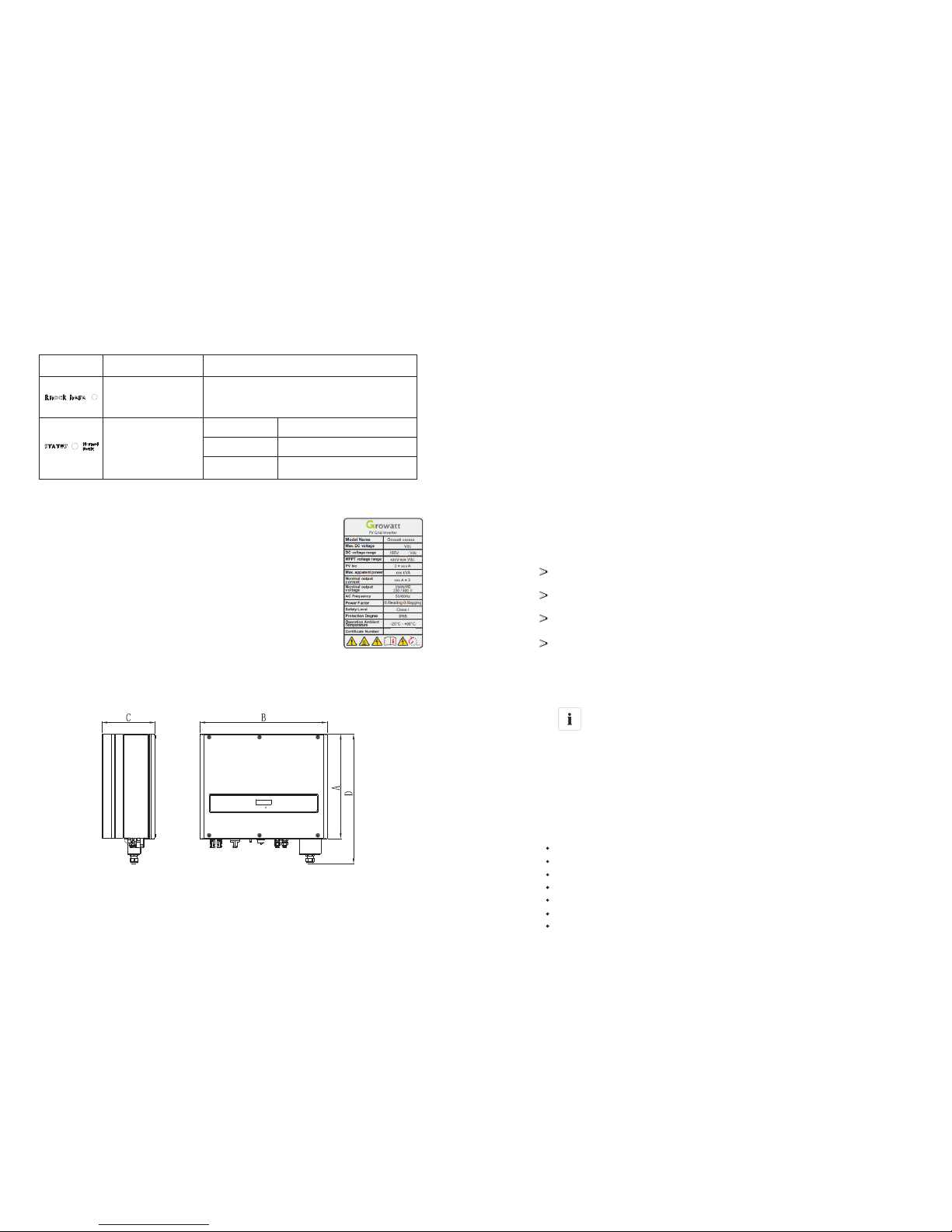
Symb ol Desc ription Expl anation
Tap sym bol Ind icate s displ ay oper ation ( see Sec tion 6) .
Inv erter s tate sy mbol
Gre en /c on st ant
Red /cons tant
Red /flas hing
Ope ratio n
Fau lt
Sof tware u pd at e
3.2 Type la bel
The type labels pro vi de a u ni qu e id en ti fi ca ti on o f th e in ve rt er ( Th e
type of pro du ct , De vi ce -s pe ci fi c ch ar ac te ri st ic s, C er ti fi ca te s an d
appro va ls ). T he t yp e la be ls a re o n th e ri gh t- ha nd s id e of t he
enclosure .
The Certificate Number is just for SAA.
Symb ol on the inve rter
*** ***
XXX
XXX
3.3 Si ze and weigh t
A(mm ) B(mm ) C(mm ) D(mm )
Wei ght (kg)
7000-150000 TL3-S
393
480
200 488 2 2
Page 9
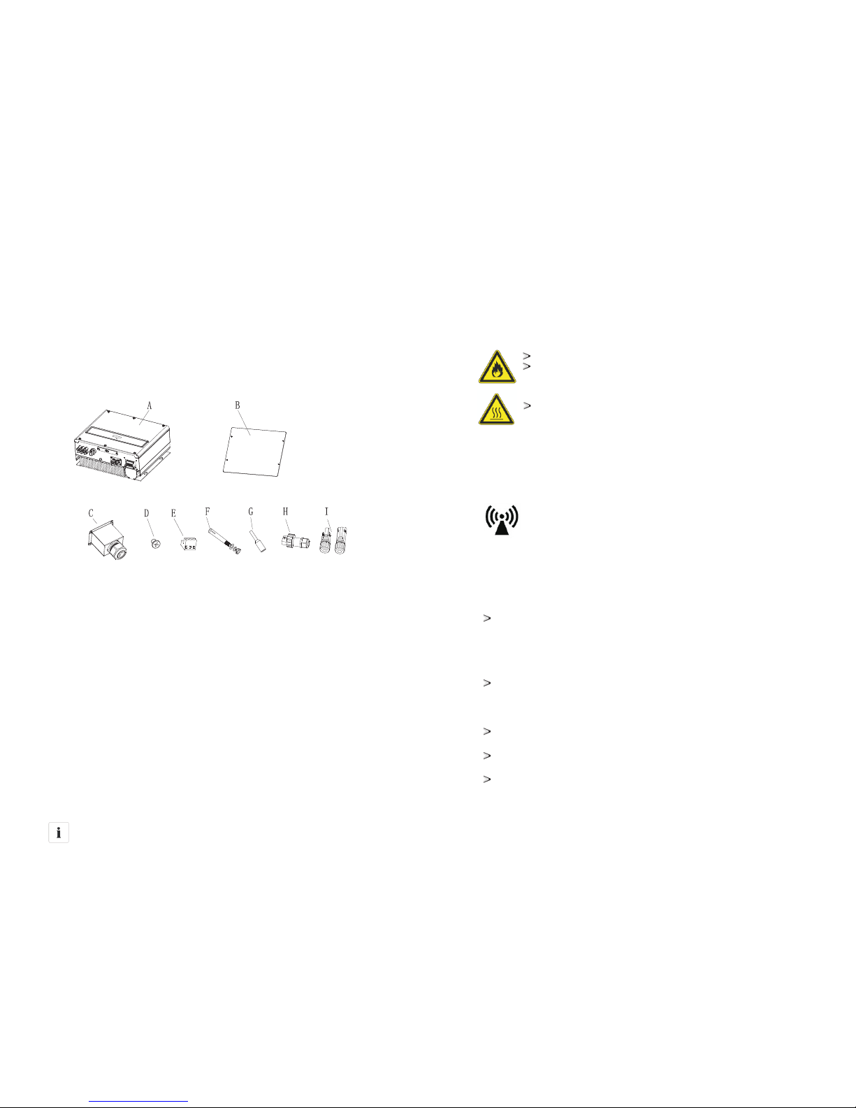
Unpacking4
Before op en in g th e pa ck in g bo x of U E se ri es i nv er te r, please note that whether there
are a ny v is ib le e xt er nal damages.
Once open the packing box, please check the delivery for completeness and for any
visible extern al d am ag es o f th e in ve rt er. If t he re a re anything damaged or missing,
please contact your dealer. Co mp le te d el iv er y sh ou ld c on ta in a s fo ll ow s.
Item
Number Descript io n
Inf ormat ion
Though the packaging box of TL3-S is durable, please trea t th e
packing box gently and avoid dispose the packing box.
11
12
A 1
Inverter
B 1
Quick inst al la ti on g ui de
C
3
Cable glan d fo r AC c on ne ct io n
D
4
M4 cros s re ce ss ed c ou nt ersunk head s crews
E 1
Rs485 term in al s
F 4
Expansio n bo lt
G
5
Cord En d Term inal
H
I*
1
2/3
RJ 45 PLUG Only for Aus tr al ia( )
PV connect or s
- -
1
User manua l (n ot s ho w in t he p ic tu re )
Installation 5
5.1 Sa fety instr uction
Danger to life due to fire or explosion
Despite caref ul c on st ru ct io n, e le ct ri ca l de vi ce s ca n ca us e fi re s.
Do not install the inverter on easily flammable materials and where
flammable materials are s to re d.
Risk of burns due to hot enclosure parts
Mount the inverter in such a way that it cannot be touched
inadvertently.
Possible damage to health as a result of the effe ct s of r ad ia ti on !
In special cases, there m ay s ti ll b e in te rf er en ce f or t he s pe ci fi ed a pp li ca ti on
are a de sp it e ma in ta in in g st an da rd iz ed e mi ss io n li mi t va lu es ( e. g. w he n
sensitive equipment is located at the setup location or when the setup
location is near radio or television re ce iv er s) .I n th is c as e, t he o pe ra to r is
obliged to take pro pe r ac ti on t o re ct if y th e si tu at io n.
Never install the inverter near the sensitive equipment(e.g. Radios,
telephone, television, etc)
Do not stay closer than 20 cm to the inverter for any length of time unless it
is absolutely necessary.
We as su me s no r es po ns ib il it y fo r co mp li an ce t o EM C regulations for the
complete system.
All el ec tr ical in st allat io ns s hall be d on e in acco rdan ce w ith the l oc al a nd
nati on al e lectr ic al code s. D o no t re move th e ca si ng. Inv er ter con ta in s no
user s er vi ceabl e pa rts. Re fe r se rvici ng t o quali fi ed s ervic e pe rsonn el . Al l
wiri ng a nd e lectr ic al inst al la tion sh ou ld be con du ct ed by a qua li fied
serv ic e pe rsonn el .
Carefull y re mo ve t he unit f ro m it s pa ckagi ng a nd insp ec t fo r exter nal
dama ge . If y ou find a ny i mperf ec ti ons, pl ea se cont ac t yo ur loca l de aler.
Be sure that t he i nvert er s co nnect t o th e grou nd in order t o prot ec t
pro perty a nd p erson al s af ety.
The in ve rt er must o nl y be oper at ed w ith PV ge ne rator. Do n ot conn ec t
any ot he r so urce to it.
Both A C an d DC v oltag e so urce s are termi na te d insid e th e PV Inve rt er.
Plea se d is conne ct t hese ci rcui ts b efore servi ci ng.
This u ni t is d esign ed t o feed po we r to t he publ ic p ower gr id ( ut ility ) on ly.
Do not c on ne ct this u ni t to an AC so urce o r ge nerat or. Conne ct in g
Inve rt er t o exter nal dev ic es coul d resu lt i n serio us d am age to yo ur
equi pm en t.
* 7000-11000TL3-S & 12000TL3 2 Pairs
* 12000TL3-S & 15000TL3-S 3 Pairs
Page 10
5.2 Se lecting th e Installa tion Locat ion
5.2. 1 Th is i s guida nc e for ins ta ll er to cho os e a suita bl e in stall at ion
loca ti on , to avoi d po tenti al d am ages to d ev ice and o pe ra tors.
1) The w al l se lecte d to i nstal l th e in verte r mu st be strong an d fi rm
enou gh t o su pport a nd b ear the w ei gh t of the in ve rter fo r a lo ng
peri od t im e.
2) The l oc at ion sel ec ted mus t be s ui table f or i nvert er s' d imens io n. (Ref er
to 3.3 D im en sions a nd F ig.5. 2 Re qu ired Clea ra nc es)
3) Do no t in st all the i nv erter o n st ru ctures co ns tr ucted o f fl ammab le o r
ther mo l ab ile mat er ials.
4) Nev er i ns tall th e in verte r in e nv ironmen t of l it tle or no a ir f low, nor
dust e nv ir on ment.
5) The I ng re ss P ro te ction r at e is IP65 w hi ch m eans th e in verte r ca n be
inst al le d outdo or s and ind oo rs .
6) Do no t ex po se the in ve rter to d irec t su nligh t, i n or de r to avoi d th e
powe r an d ef fi cienc y de ra ting ca us ed by exc es si ve heat in g.
7) The a mb ie nt temp er ature of the in ve rter sh ou ld b e -25℃~+6 0℃.
8) The i ns ta llati on l ocati on m us t be freely a nd s af ely to ge t at a ll time s.
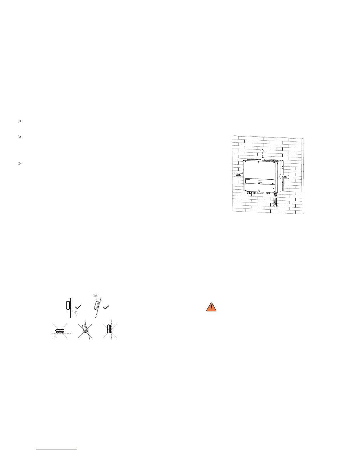
9) Vert ic al ly inst al latio n an d ma ke sure the c on ne ction o f in verte r mu st
be dow nw ar ds . Never i ns ta ll hori zo ntal an d av oi ds forw ar d an d
side wa ys t ilt.( R ef er to dra wi ng s below )
13
14
When a p ho to volta ic p anel is e xp os ed to lig ht , it gene ra te s a DC volt ag e.
When c on ne cted to t hi s equip me nt , a photo vo ltaic p an el w ill cha rg e the
DC lin k ca pa citor s.
Ener gy s to re d in this e qu ip ment' s DC l ink cap ac it ors prese nt s a ri sk of
elec tr ic s hock. E ve n after t he u ni t is disc on necte d from t he g rid and
phot ov ol taic pa ne ls, hig h vo lt ages ma y st ill exi st i ns ide the P V-I nvert er.
Do not remov e th e casin g un ti l at leas t 5 mi nutes a ft er d iscon ne cting a ll
powe r so ur ce s.
Alth ou gh d esign ed t o meet al l sa fe ty requiremen ts , some pa rt s an d
surf ac es o f Inver te r are st ill hot d ur ing ope ra ti on. To reduce t he r is k of
inju ry, do not to uc h th e heat si nk a t the bac k of t he P V-Inve rt er or nea rb y
surf ac es w hile In ve rter is o pe ra ting.
Fig5.1
11) Do n ot i ns tall th e in verte r ne ar t elevi si on ante nn a or a ny othe r an tenna s
and an te nn a cable s.
12) Do n ot i ns tall th e in verte r in l iv ing area, t he n oi se caus ed b y the
mach in e ma y affect on d ai ly l ife.
13) Fo r se cu rity reas on s, d on't in st all the i nv er ter in pl ac e where the
chil dren c an r ea ch .
10) No ti ce t he mini mu m clear an ce s of the in ve rter. (Re fer to 3. 3 Di me nsion s
and Fi g. 5. 2 Requi re d Cl ea rance s) .
Fig5.2
5.3 In stallati on guide
5.3. 1 Mounting E xpansion B olt
DANGER
In orde r to a vo id e le ct ri ca l sh oc k or o th er i nj ur y, inspect existing
electro ni c or p lu mb in g in st al la ti on s be fo re d ri ll in g ho le s.
To mou nt t he i nv er te r on t he w al l, w e sh ou ld m ou nt e xp an si on b ol t to t he
wall firmly first.
Page 11
Hint: Data units in mm
Steps:
Drill four holes for expansion bolt use the Fix Hole Paper as template.
Fix the mounting expansion bolt on the wall as the figure s sh ow n be lo w, co mb in e
four expansion bolt with four M6 nuts. Refer to Fig 5.4.
Fig5.3
15
16
Fig5.4
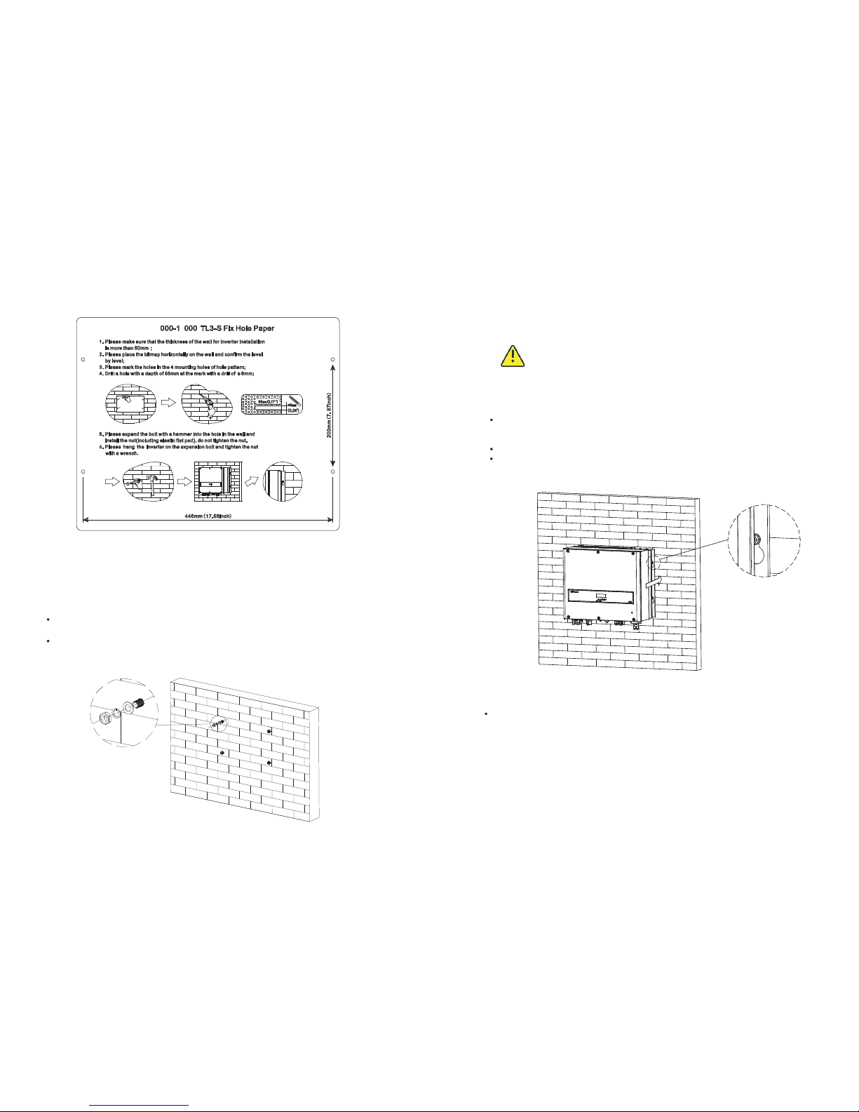
5.3. 2 Mounting I nverter
WAR NI NG
Falling equipment can cause serious or even fatal injury, ne ve r
mount the inverter on the bracket unless you are su re t ha t th e
mounting frame is rea ll y fi rm ly m ou nt ed o n th e wa ll a ft er c ar ef ul ly
checking.
After expansion bolt is firmly mounted on the wall, then mount the inverter on
expansion bolt.
Rise up the inverter a little higher than expansion bolt. Considering the weight of
inverter, yo u ne ed t o ha ng o n th e in ve rt er. Du ri ng t he p ro ce ss p le as e ma in ta in
the balance of the TL3-S.
Hang the inverter on the expansion bolt.
After confirming the inverter is stuck on expansion bolt, fasten four M6 scre ws .
Refer to Fig 5.5.
Fig5.5
Connection of a second prot ec ti ve c on du ct or
In some installation countries, a second prot ec ti ve c on du ct or i s re qu ired to
pre ve nt a t ou ch c ur re nt i n
the event of a malfunction in the original prot ec ti ve c on du ct or.
For installation countries falling within the scope of validity of the IEC standard
62109, you must install
the pro te ct iv e co nd uc to r on t he A C te rm in al w it h a co nd uc to r cr os s- se ct io n of a t
least 10 mm²Cu.
Or Install a second pro te ct iv e co nd uc to r on t he e ar th t er mi na l wi th t he s am e cr os s-
section as the original
pro te ct iv e co nd uc to r on t he A C te rm in al . Th is p re ve nt s to uc h cu rrent if the
original prot ec ti ve c on du ct or f ai ls .
5
7
Page 12

17
18
5.3. 3 Installa tion layou t
Informat io n
Avo id e xp os in g in ve rt er t o di re ct s un li gh t, r ai n or s no w to e xt en d
the inverter service life despite the IP65 prot ec ti on d eg re e. E xp os ure
to the sunlight may cause additional inter na l he at in g wh ic h wi ll
cause power derating.
More th an o ne i nv er te r ne ed t o be i ns ta ll ed , th e di me ns io ns b el ow s ho ul d be
considere d.
Fig5.6
Fig5.7
Fig 5.8
Recommend awning installation, the purpose is to extend the inverter service life and
red uc e th e po we r de ra ti ng o f th e in ve rt er. The dimension of the awning, ref er t o Fi g
5.9.
Fig 5.9
Page 13

19
20
5.4 El ectrical C onnectio ns
5.4. 1 Safety
DANGER
Danger to life due to lethal voltages!
High voltages which may cause electric shocks are p re se nt i n
the conductive parts of the inverter. Pr io r to p er fo rm in g an y
work on the inverter, di sc on ne ct t he i nv er te r on t he A C an d
DC sides
WAR NI NG
Danger of damage to electro ni c co mp on en ts d ue t o
electro st at ic d is ch ar ge .
Take approp ri at e ES D pr ec au ti on s wh en replacing and
installing the inverter.
5.4. 2 Wiring AC Ou tput
Conditions for the AC Connection
You mu st c om pl y wi th t he c on ne ct io n require me nt s of y ou r ut il it y op er at or.
All usages must comply with the reg ul at io ns .
Residual-current protective device
The inverter is equipped with an integrated universal res id ua l- cu rr en t mo ni to ri ng
unit.
If the network operator stipulates a re si du al -c ur re nt p rotective device, you must use
a res id ua l- cu rr en t protective device that triggers in the event of a res id ua l- cu rr en t of
300 mA or more.
Load disconnection unit
You mu st i ns ta ll a s ep ar at e th ree-phase miniature c ir cu it -b reaker or other load
disconnection unit for each inverter in ord er t o en su re t ha t th e in ve rt er c an b e sa fe ly
disconnected under load.
Measure t he p ub li c gr id v ol ta ge a nd f re qu en cy ( Vol ta ge : 40 0Va c; F requency:
50Hz/60Hz; 3-Phase);
Open the brea ke r be tw ee n th e PV i nv er te r an d ut il it y;
Specification of AC bre ak er :
Cable req ui re me nt s:
1. Th e AC side t ermin als of th e inver ter are l ik e th e fo llowi ng figu re,Fi g. 6 a, i t is c lear to
con firm th at 'L1, L 2, L3' re pr ese nts thr ee l iv e li ne o utp ut, "N" r ep resen ts neut ral lin e
and i s groun di ng l in e.
2. Th e five ca bles sh ould be p ut thro ug h th e pro tecti on shel l, as Fig . 6 b, crim p five
sta ndard c ab le s wi th Cord E nd Ter mi na l. T ig ht en all sc rews. Re fe r to F ig. 6c.
3. Fa sten th e prote ct io n sh ell ont o the bot tom of th e inver ter, mak e su re th e fo ur s cre ws
are t ig ht en ed, the c omple ted app earan ce is lik e the bel ow figu re Fig. 6 d.
Con necti on to the A C side te rmina l
a) b)
c) d)
Fig 6
5.4. 3 Wiring DC In put
Danger to life due to lethal voltages!
Before co nn ec ti ng t he P V ar ra y, ensure th at t he D C sw it ch a nd A C
bre ak er a re d is co nn ec t from the inverter. NEV ER c on ne ct o r
disconnect the DC connectors under load.
DANGER
7000TL3-S 16A/400V
8000TL3-S 20A/400V
9000-12000TL3-S 25A/400V
15000TL3-S 32A/400V
Out side di amete r of cabe l(mm)
AWG 8
AWG 10
AWG 12
Con ducto r
Cro ss s ect ion
40m
700 0TL3- S 8000 TL3-S 900 0TL3- S 100 00TL3 -S
110 00TL3 -S
120 00TL3 -S
150 00TL3 -S
32m 28m
Max . cable l ength (m)
18- 25
25m 20m 17m
60m 55m 44. 5m 40m 3 7m 2 7m
43m/ / / / /
Page 14

21
22
WAR NI NG
Impro pe r op er at io n du ri ng t he w ir in g pr oc es s ca n ca us e fa ta l in ju ry t o
operator or unrec ov er ab le d am ag e to t he i nv er te r. Only qualified
personnel can perform the wiring work.
Risk of damage to the inverter.
If the voltage of the PV modules exceeds the maximum input voltage of
the inverter, it c an b e de st royed by the overvoltage. This will void all
warranty claims.
Do not connect strings to the inverter that have an open-circ ui t vo lt ag e
gre at er t ha n th e ma xi mu m in pu t vo lt ag e of t he i nv er te r.
To redu ce t he r is k of e le ct ri c sh oc k, a vo id t ou ch in g th e li ve c om po ne nt s
and tre at t he t er mi na ls c ar ef ul ly.
Informat io n
Please use the same brand male and female PV connectors.
Under any conditions the total circ ui t cu rr en t sh ou ld n ev er e xc ee d th e
Max. Curren t.
NOTICE
Excessive voltages can destro y th e me as ur in g de vi ce
Only use measuring devices with a DC input voltage range up to at least
1000 Vdc.
1 Check the connection cables of the PV modules for corre ct p ol ar it y an d ma ke s ur e
that the maximum input voltage of the inverter is not exceeded.
2 The diagram drawing of DC side is shown as below, notice that the connectors
are i n pa ir ed ( ma le a nd f em al e co nn ec to rs ).
Fig 6.1
F ig 6 . 2
Page 15

5.4. 4 Groundin g
AC Groundi ng
The TL3-S series inverter must be connected to the AC gro un di ng c on du ct or o f th e
power distribution grid via the gro un d te rm in al ( PE ).
PV Groundi ng
The gro un di ng c on du ct or i n th e fr am ew or k of t he P V ar ra y mu st b e co nn ec te d to t he
PV grou nd in g co nd uc to r an d th e DC g ro un di ng c on du ct or. Th e cr os s- se ct io n of t he
gro un di ng c on du ct or c or re sp on ds t o th e cross-section of the largest conductor in the
DC system.
DC Groundi ng C on du ct or
A DC grou nd in g co nd uc to r ma y be r eq ui red by the Authority Having Jurisdiction
(AHJ). Use the terminal block for the PV grou nd in g co nd uc to r an d DC g ro un di ng
conductor.
5 In orde r to s ea l th e in ve rt er, all unneeded DC inputs must be closed with sealing
plugs:
Cable req ui re me nt s:
Model
Diameter (m m) Area(mm² )
AWG
7000-150 00 TL 3- S
1.63-2.0 5 2.5-4 1 4-12
3 Check the assembled DC connectors for corre ct p ol ar it y an d co nn ec t th em t o th e
inverter.
4 The maximum string curren ts a re v ar yi ng f rom diffe re nt i nv er te r ty pe s.
Model
Max.curr en t
7000TL3- S
8000-900 0T L3 -S
10000-11 00 0T L3 -S
12000TL3
12000-15 00 0T L3 -S
11.5A/11 .5 A
11.5A/11 .5 A
13A/13A
11.5A/11 .5 A
20A/10A
Ground kit
If PV modules of the PV system re qu ir e PO SI TI VE o r NE GATIVE to connect to
GROUND, the output of inverter should connect to grid with an isolating
transformer. The c on ne ct io n me th od i s be lo w:
N of transformer should not be connected to PE.
Inv erter
L1
L2
L3
N
PE
5.5 Gr id Type
5.5. 1 Common gri d type
Based on the local GRID standards , it m ay s el ec t di ff erent connection types. In the
following you will find an overview of the most common type of grid structure .
Transformer
L1
L2
L3
PEN
PE
TL3
TN-C
Transformer
L1
L2
L3
N
PE
TL3
TN-S
Transformer
L1
L2
L3
N
PE
TL3
TN-C-S
Transformer
L1
L2
L3
N
PE
TL3
TT
Transformer
L1
L2
L3
PE
TL3
IT
5.5. 2 Compatib ility Table
Gri d type TN- C grid T N-S g rid TN-C -S grid TT gr id IT gr id
Gri d type
800 0-110 00TL3 -S
yes
(N an d PE of inv erter b oth
sho uld con nect to P EN of gri d.)
yes yes
yes ,
if UN -PE < 30V
yes ,
if UN -PE < 30V
23
24
Page 16

25
26
6 Commissioning
6.1 Co mmission t he Inverte r
1) Remove all covers from t he P V ar ra y.
2) Check the PV and AC voltage.
3) Plug in the PV input.
4) Tur n th e DC D is co nn ec t to p os it io n "I ".
5) If the inverter is connected with PV panel arrays and the input voltage is higher
than 160Vdc, while the AC grid is not connected yet, LCD will display messages in
ord er a s be lo w:
Company info Basic info State info
The LCD will display “ AC V outrange “at State info and the LED turn s red.
Please check all information on the LCD, operate by knocks you will see the
diffe re nt p ar am et er s.
Single knock to Light the backlight State info (single knock) Input info
(single knock) Output info
6) Tur n on t he A C br ea ke r be tw ee n in ve rt er a nd g ri d, t he
system will operate automatically.
7) Under normal operating conditions, the LCD displays
'Power: xx.xx Kw' at State info, this is the power feed into
grid. The LED turn s green.
8) Check the time and date of inverter as follow:
Single knock to Light the backlight State info (Thrice
knock) Inverter info (single knock) System T im e( do ub le
knock), if they are n ot c or re ct , pl ea se s et t he m, refer to
6.3.5 setting inverter time and date.
9) Finish commissioning.
6.2 Op eration Mo des
Normal Mod e
In this mode, the inverter works normally and LED turn s green.
Whenever the DC voltage is higher than 200Vdc, inverter converts power to grid
Whenever the DC voltage is lower than 180Vdc, the inverter will work in waiting
status and attempt to connect the grid. In waiting state the inverter consumes
just power generated by the PV panel to monitor the intern al s ys te m.
Notes: The inverter starts up automatically when DC power fro m th e PV p an el i s
suffi ci en t.
Fault Mode
The intern al i nt el li ge nt c on troller can continuously monitor and adjust the system
status. If inverter finds any unexpected conditions such as system fault and inverter
fault, the fault information will be displayed on the LCD. In fault mode the LED tur ns
red .
Notes: a) Detailed fault information re fe rs t o Ch ap te r 9 Trou bl e sh oo ti ng .
b) When PV Isolation erro r oc cu rr ed i n SA A sa fe ty s ta nd ard, the buzzer will
give an alarm every fifteen seconds.
Derating m od e
When AC fre qu en cy i s hi gh er t ha n 50 .3 Hz (s et ta bl e) , th e in ve rt er w il l de ra te i ts
output power accord in g to t he r ul e.
When user set the output limit command to the inverter, th e in ve rt er w il l al so l im it
the output accord in g to t he s et ti ng .
In this derating mode, the LCD will show “DERATI NG ”.
6.3 Co untry Sett ing and LCD Di splay
In the lower right cor ne r of i nv er te r th ere is the LCD display. We can check inverter
running state, historical generation data, etc, on the LCD scre en . It em s di sp la ye d ca n
be changed by knock; you can also change some inverter parameters by knock.
6.3. 1 Location o f the countr y setting DI P switch
The DIP switch is located on the left of the RS232 interface at the bottom of the
inverter, as t he f ig ure below.
To redu ce t he r is k of e le ct ri c sh oc k, b ef or e se le ct in g co un tr y, ple as e tu rn
off D C in pu t an d AC g ri d, t ha n un sc re w th e da m- bo ard of the DIP switch
by approp ri at e to ol .
WAR NI NG
Shutdown M od e
Inverters automatically stop running during periods of little or no sunlight. In
shutdown mode the inverters take no power fro m th e gr id a nd p an el , an d th e LC D
and LED turn s off.
Notes: If the PV string DC voltage is too low, the inverter will also tur n to S hu td ow n
Mode.
Page 17

27
28
The intern al s tr uc tu re of the DIP switch is as the following figure :
6.3. 2 DIP switch o ption corr espondin g to the count ry
DANGER
When you setting the DIP, you m us t tu rn o ff t he A C bre ak er a nd D C
bre ak er.
Informat io n
After setting the DIP, plea se p ow er o n th e in ve rt er a nd c he ck t he
model display. If th e la st c ha ra ct er o f th e mo de l na me i s
corre sp on di ng t o th e co un tr y sa fe ty s ta nd ar d as t he a bo ve t ab le , it
means your setting is successful.
You sh ou ld c ha ng e th e ti me d is pl ay ed o n th e LC D of i nv er te r to
your local time after inverter starts up.
If the country is set incorrectly, ple as e sh ut d ow n th e in ve rt er
and set again.
When the cables of AC side and DC side are al l we ll c on ne ct ed , be fo re
commissioning, the country safety standard mu st b e se le ct ed b y th e DI P sw it ch .
The DIP switch is composed of four-digit binary number PINS. The diffe re nt
combination of the four PINS can re pr es en t di ffere nt i nv er te r' s mo de l, w hi ch i s
corre sp on di ng t o th e lo ca l gr id s ta nd ar d. E ac h sm al l wh it e PI N ha s tw o st at us es ,
when set upward t o 'O N' , it s va lu e tu rns to '1', when set downward, i ts v al ue t ur ns
to '0'. Concer ni ng t he m at ch in g of t he P IN s ta tu s an d th e co un tr y sa fe ty s ta nd ard,
please re fe r to t he t ab le b el ow :
Swit ch to countr y table 6.3. 1
DIP sw itch statu s Coun try Model d isp lay
VDE 0126 GTXXXXXXX1
G59-3
GTXXXXXXX2
42 31
ON
5
42 31
ON
5
AS4777-Australia
GT0XXXXXX3
CEI 0-21
GT0XXXXXX4
SP1699/Spain GT0 XX XX XX 5
Gre ec e GT0XXXXXX6
VDE-AR-N4105
GT0XXXXXX7
G83-2
GT0XXXXXX8
EN50438-Ire la nd
GT0XXXXXX9
CQC
GT0XXXXXXA
EN50438-Default
GT0XXXXXXB
42 31
ON
5
42 31
ON
5
42 31
ON
5
4
2 31
ON
5
42 31
ON
5
42 31
ON
5
42 31
ON
5
42 31
ON
5
42 31
ON
5
Page 18

29
30
IEC61727&IEC62116
GT0XXXXXXC
Belgium
GT0XXXXXXD
Thailand MEA
GT0XXXXXXE
42 31
ON
5
42 31
ON
5
42 31
ON
5
42 31
ON
5
Thailand PEA
GT0XXXXXXF
42 31
ON
5
42 31
ON
5
42 31
ON
5
42 31
ON
5
42 31
ON
5
AS4777_Newzealand
GT1XXXXXX0
Reserved
GT1XXXXXX1
India
GT1XXXXXX2
EN50438_Demark
GT1XXXXXX3
EN50438_Sweden
GT1XXXXXX4
EN50438_Norway
GT1XXXXXX5
VFR2013
GT1XXXXXX6
VFR2014
GT1XXXXXX7
Reserved
GT1XXXXXX8
Reserved
GT1XXXXXX9
42 31
ON
5
42 31
ON
5
42 31
ON
5
42 31
ON
5
42 31
ON
5
Page 19

31
32
6.3. 3 Display in terface
Overall display interface intro du ct io n
Three
Double
Double
Once
Double
Set Date/Time
Date:2012/04/05
Time:14:20:38
Once
Double
AC V Control:
Enable
Model:
PV0000F161
FW Version:
DH 1.0–DH 0.0
1 AC F Outrange
Time:14:20:30
FW Version:
Build:dhaa-0101
Date:2012/04/05
Time: 14:20:38
Once
Once
Once
Once
Once
Once
Double
Double
Double
Once
Once
Double Once
Once
Double
Once
Once
Once
Double
Once
Once
Once
Once
Once
Once
Once
AC VA/Watt:
VA W
Connect OK
AC V Control :
Disable/Enable
Set Com Address
003
Set Com Address
003
AC V Control :
Disable
Input Word:123
000
Input Word:123
123
Growatt
PV Inverter
SerNo:
PR34200090
Setting
Model:
PVBC00F161
FW Version:
DH 1.0–DH 0.0
Connect in: s
Etoday:
50 .2 Kwh
Power info
Input Info
Eall:
2000 Kwh
Etoday:
50 .2 Kwh
PV1 Volt: V
Power: W
PV2 Volt: V
Power: W
Output Info
GridFreq:50.0Hz
Set Info
Inverter info
SerNo:
PR34200090
COM Addr:
003
Power Rate: 20%
P_Factor: 1.0
AC VA/Watt:
VA W
1. Once: Next page
2. Double:Enter
3.Three: Enter the setting
4.Four: Back to cycle display interface
AC Error Record
1 AC F Outrange
Date:2016/04/06
1 AC F Outrange
AC F:48Hz
2 AC V Outrange
AC V:20.2V
2 AC V Outrange
Date:2016/04/06
2 AC V Outrange
Time:14:20:30
Eall:
2000 Kwh
AC Volt A/B/C
230V/230V/230V
Set Language Set Language
English
Once
Once
Once
Double
Fig6.3 Overall display interface
Powe r on display
After inverter re st ar ts , th e ba ck gr ou nd l ig ht w il l la st f or 2 s ec on ds . You ca n ch ec k th e
inverter series number, mo de l, f ir mw are version. Refer Fig6.3.1.
Growatt
PV Inverter
SerNo:
PR34200090
Model:
PVBC00F161
FW Version:
DH 1.0–DH 0.0
Fig6.3.1Power on display
6.3. 4 Operate by k nock
Knoc k type and def inition
Tabl e 6. 3. 2 Kn oc k de fi ni ti on l is t
Knoc k ty pe
Defi ni ti on
Sing le k no ck D own
Doub le k no ck Ente r
Knoc k fo ur t imes
Back t o cy cl e displ ay i nterfac e
The inverter can support four kinds of knock: single knock, double knock, third
Knock, Knock four times. Each kind of knock has diffe re nt f un ct io n. R ef er t o
specified definition in Table 6.3.2.
Thre e kn oc k Make s ur e se tting
Ligh t backligh t and single k nock to chec k running in formatio n
Before li gh t th e ba ck li gh t, t he f ou r ty pe s of k no ck f un ct io ns a re t he s am e, w hi ch i s
just lighting the backlight. Note that the backgrou nd l ig ht in g wi ll a ut om at ic al ly t ur n
off i f th er e is n o kn oc k de te ct ed i n 10 s ec on ds .
During cloudy days or in the area o f lo w li gh t, i t’s in co nv en ie nt f or u se rs t o ch ec k
inverter running information such as status, input data, output data, energy
generated. In this case user can light the backlight and check those data by single
knock, a single knock will switch LCD scree n to a f ol lo wi ng i nt er fa ce .
Page 20

6.3. 5 Data check ing and para meters set ting
Cycl e display
If you do not knock the enclosure l id , LC D di sp la y fo ll ow in g in fo rm at io n cy cl e by
cycle. Refer Fig 6.3.3.
Fi g 6 . 3. 3 Cyc le di s pl ay
Para meters set ting
AC VA/Watt:
VA W
Etoday:
50 .2 Kwh
Eall:
2000 Kwh
Fig 6.3.4 is the setting information. Single knock, the Text will display the setting.
Double knock, the Text will display”input123: 000”. Single knock to go back Setting
page. Double knock the enclosure li d re ad y to i np ut p as sw ord. Single knock to
change value of first, double knock enter into next position. Konck three t im es w he n
the bit was “123”, it will go into Setting options.
Input Word:123
000
Input Word:123
000
Double
Input Word:123
100
Input Word:123
100
Input Word:123
110
Once
Once
Double
Input Word:123
120
Once
Input Word:123
120
Double
Input Word:123
121
Once
Input Word:123
122
Once
Input Word:123
123
Once
Setting
Double
Three
Input OK
33
34
Fi g 6 . 3. 4 set tin g s ec ond l eve l m en u and it s sub - me nus
Set Com Address
001
Set Language
Set Date/Time
AC V Control :
Disable/Enable
Once
Once
Once
Setting
Three
Set Language
English
Double
AC V Control :
Disable
Double
Double
Date:2012/04/05
Time: 14:20:38
Sett ing langua ge
To change inverter’s displaying language, please select Setting->Set language, then
LCD scree n wi ll d is pl ay c ur re nt l an gu ag e ty pe , si ng le k no ck t o ch an ge c ur rent
language, knock three t im es w il l sa ve c ha ng es a nd d is pl ay s “S et O K! C ur re nt
Language English” Refer Fig 6.3.5. Knock four times to exit setting.
Set Language
Set Language
English
Set Language
xxxx
Once
Three
Set OK
Fi g 6 . 3. 5 set tin g l an gua ge
Please note in orde r to p re ve nt d is op er at io n, s ys te m la ng ua ge w on ’t be change in
second level menu “Set language”, but it will be only if user saves save the choice by
knock three t im es a nd L CD d is pl ay s “S et O K! ”
Setting inverter’s COM addres s
When communicating with monitoring software o r de vi ce , th e so ft wa re o r de vi ce
may reg ar d in ve rt er ’s COM a dd ress as communication addre ss ( Al so m ay u se
inverter’s serial number as communication addre ss ). Th e CO M ad dr es s co ul d be
assigned. The second level menu “Set COM Addr” of setting is to set inverter’s COM
addre ss .
Page 21

35
36
Setting COM addre ss
Input password- >S et ti ng l an gu ag e- >S et C OM a dd r-> i s th e cu rr en t ad dress of
inverter.” Do ub le k no ck t he e nc lo su re lid re ad y to i np ut C OM a dd r. Single knock to
change COM Addr. Kno ck t hree times to save COM Addr. Ref er F ig 6 .3 .6 . Kn oc k fo ur
times to exit setting.
Set Com Address
001
Set Com Address
001
Set Com Address
012
Set Com Address
002
Set Com Address
002
Set Com Address
012
Set Com Address
112
Set OK
Double
Once
Double
Once
Double
Once
Three
Fi g 6 . 3. 6 cur rent COM A ddr
Setting inverter time and date
Inverter prov id es a s ys te m cl oc k; u se r mu st s et t he s ys te m ti me a ft er i ns ta ll at io n, a s
the historical statistic data for a period were b as ed o n th e cl oc k. U se r ca n se t th e
following time parameters: year, mon th , da y, hou r, minute.
Input password- >S et ti ng -> 2 01 7/ 03 /2 7 00 :3 8 -> is t he c ur re nt t im e. D ou bl e kn oc k to
go into setting. Single knock to change time. Konck three t im es t o sa ve t im e. K no ck
four times to exit setting. Refer Fig 6.3.7.
Date: 2012/04/05
Time: 14:20:38
Date: 2013/04/05
Time: 14:20:38
Date: 2013/04/05
Time: 14:20:38
Date: 2013/05/05
Time: 14:20:38
Set Date/Time
Date: 2013/05/06
Time: 14:20:38
Date: 2013/05/06
Time: 14:20:38
Date: 2013/05/06
Time: 15:20:38
Date: 2013/05/06
Time: 15:20:38
Date: 2013/05/06
Time: 15:21:38
Set OK
Double
Once
Double
Once
Double
Once
Double
Once
Double
Once
Three
Date: 2013/05/05
Time: 14:20:38
Fi g 6 . 3. 7 inv ert er da te an d tim e
6.4 Do uble MPPT of t he TL3-S
The TL 3- S i nc lu de s du al in pu t section t o p rocess t wo st ri ng s wi th in de pe nd en t MPPT,
high speed and precise MPP T alg or it hm fo r rea l- ti me po we r tra ck in g and energy
harvesting, as w el l as tra ns fo rm er le ss ope ra ti on for h ig h p er fo rm an ce , th e ma x
conversion e fficiency is up to 98 .3 %. T he wide i np ut v ol ta ge ran ge mak es the
inverter suitable to low power operation as well as the high power operation.
As th e wea th er influence an d the l oc at io n of two M PP T PV arrays di ffere nt , the
power o f t he MP PT A inp ut s i s diffe re nt fr om th e power i np ut s o f t he MPPT B a t the
same time, t he TL 3- S wor ks at a non-symmetrical i np ut st at us . But th e MPP T
algorithm of th e i nv er te r m ak es it tr ac ki ng th e m ax im um po we r p oi nt of ev er y M PP T
channel to improv e th e en er gy u ti li za ti on o f th e PV a rr ay s.
6.5 Co mmunicat ion
6.5. 1 Using shin ebus to set th e informat ion of the inv erter or
upda te firmwar e
About the software of s hi ne bu s an d th e us ag e of i t pl ea se d ow nl oa d fr om t he w eb :
www.grow at t. co m
Page 22

37
38
6.5. 2 Monitor th e inverter s
The inv er te r pro vi de s RS4 85 interface an d RS2 32 interface to co mm un ic at e with
rem ot e PC or logg er. User ca n monitor t he inverter st at us via t he following t yp es of
communication systems.
You ca n up da te f ir mw are via RS232 or Rs485
The connecting diagram as follow:
Active power control with a ripple control signal receiver
Through RS485 interface-RS485-232 /RS232 converter- PC .
Informat io n
If yo u plan to u pd at e fir mw ar e via RS4 85 , please di sc on ne ct t he
monitor device.
Through RS485 interface-Data logger-P C.
Plan A:
Through RS232 interface- wireless module-Data logger- In te rn al et .
Page 23

39
40
Plan B
Informat io n
When t hr ee phase in ve rt er an d si ng le -p ha se in ve rt er sh are d a RS 48 5
communication line, the total length of which does not exceed 1km.
6.5. 3 RS485 cabl e connecti on
Rs48 5 cable conn ection
Pin1------- TR-(B)
Pin2------- Shielding layer
or no connection
Defi nitions of R S485 PLUG (s tandard) a s follows:
Pin1------- TR-(B)
Pin2------- Shielding layer
or no connection
Pin3------- TR+(A)
Pin3------- TR+(A)
1. Please loosen four screw s, t ak e do wn t he R S4 85 w at er pr oo f co ve r from inverter. If
you don’t c ho os e RS 48 5 as c om mu ni ca ti on m et ho d, k ee p it o n th e in ve rt er.
Page 24

41
42
2. Slightly loosen the swivel nut, re mo ve t he f il le r-p lu g fr om t he M 16 c ab le g la nd .
Informat io n
Pull cables outward s to c on fi rm w he th er t he y ar e in st al le d fi rm ly
3. Ma ke th e cable t hrough th e h ol e of ca bl e g la nd and p ut th e cable i nt o t he Rs485
terminals, fix all cab le s with screwdriver (‘1’to’ T/R- (B )’ , ‘3’t o’ T/R +( A) ’, ‘2’ to the
shielding layer or no connection). The type of cable is rec om me nd ed a s ST P, FTP,ASTP.
4. Plug in two terminals. Cover the fix board .
Informat io n
Ti gh te n 4 pc s sc rews first, then tighten cable gland.
5. T ig ht en 4 pc s sc rews and cable gland.
Note:
1) As to the connection between inverters, please ref er t o th e fo ll ow in g fi gu re .
2) As to the connection between inverter and ShineWeb Bo x, p le as e re fe r to t he
following figure.
6.5. 4 Inverter d emand resp onse modes ( DRMs,onl y for Austra lia)
This s er ie s i nv er te r h as the fu nc ti on of de ma nd res po ns e m od es , We us e R J4 5 socket
as inverter DRED connection.
6.5. 4.1 Defini tions of RJ4 5 socket pin s as follows :
Page 25

43
44
Pin1------- DRM5
Pin2------- DRM6
Pin3------- DRM7
Pin5------- RefGen
Pin6------- COM/DRM0
Pin4------- DRM8
Pin7------- NC
Pin8------- NC
6.5. 4.2 Defini tions of RJ4 5 plug pins as f ollows
No. of RJ45 plug
1
2
4
5
3
6
7
white and orange
orange
blue
white and Blue
white and gre en
gre en
white and bro wn
Color of the wire s
8
bro wn
6.5. 4.3 Method o f assertin g demand res ponse mode s
MODE
DRM0
DRM5
DRM7
DRM8
DRM6
5
1
3
4
2
Rj45 socket
Asserted by shorting pins
Operate the disconnection device
Do not generate power
Do not generate at more t ha n 75 % of r at ed
power AND Sink re ac ti ve p ow er i f ca pa bl e
Incre as e po we r ge ne ra ti on ( su bj ec t to
constraints fro m ot he r ac ti ve D RM s)
Do not generate at more t ha n 50 % of r at ed
power
Require me nt
8
5
5
5
5
Start-Up and shut down the inverter 7
7.1 St art-Up the i nverter
1.Tur n on t he A C gr id b re ak er ;
2.Tur n on t he D C sw it ch o f th e in ve rt er, and the inverter will start automatically when
the input voltage is higher than 160V.
7.2 Sh ut down the In verter
1.Tur n of f th e AC g ri d breaker;
2.Tur n of f th e DC s wi tc h of t he i nv er te r.
3.Check the inverter operating status.
4.Until the display of LCD goes out, the inverter is shut down.
Once t he ou tp ut po we r i s d er at in g because of t oo hi gh wa rm in g, so me ti ps ca n help
you solve such prob le ms :
The air grills are cl og ge d. To cl ea n th e ai r gr il ls o r he at s in k.
Ventilation of installation location is poor. Cho os e ap propriate installation
location before m ou nt in g.
8.1 Cl eaning the I nverter
If the in ve rt er is di rt y, tu rn -o ff the AC breaker and DC switch, wait in g th e inve rt er
shut down, then clean the enclosure l id a nd t he d is pl ay u si ng o nl y a wet cloth. Do not
use any cleaning agents (e.g. solvents or abrasives).
8.2 Ch ecking the D C Disconne ct
8 Maintenance and Cleaning
Check f or ex te rn al ly visi bl e d am ag e a nd disc ol or at io n o f t he DC Di sc on ne ct an d the
cables at re gu la r inte rv al s. If th er e is an y visible da mage to the DC Di sc on ne ct , or
visible discoloration or damage to the cables, contact the installer.
Once a year, tur n th e ro ta ry s wi tc h of t he D C Di sc on ne ct f rom the “On” position
to the “Off ” po si ti on 5 t im es i n su cc es si on . Th is c le an s th e co nt ac ts o f th e ro ta ry
switch and prol on gs t he e le ct ri ca l en du ra nc e of t he D C Di sc on ne ct .
Page 26

45
46
9 Trouble shooting
Our q ua li ty contro l pro gr am assu res t ha t every i nv er te r is ma nu fa ct ur ed to accu ra te
specifications and is th or ou gh ly te st ed be fo re leaving o ur fa ct or y. I f y ou ha ve
diffi cu lt y in the o pe ra ti on of your i nv er te r, p le as e rea d thr ou gh th e fol lo wi ng
information to correc t th e pr ob le m.
9.1 Er ror Messag es display ed on LCD
An e rr or m es sa ge wi ll be d is pl ay ed on t he LC D sc re en wh en a fa ul t occurs. T he faults
consist of system fault and inverter fault.
You ma y be a dv is ed to co nt ac t manufacture r in s om e situation, plea se prov id e the
following information.
Information concer ni ng t he i nv er te r:
Serial number
Model number
Error m es sa ge o n LC D
Short description of the prob le m
Grid voltage
DC input voltage
Can you rep ro du ce t he f ai lu re? If yes, how?
Has this prob le m oc cu rr ed i n th e pa st ?
What was the ambient condition when the pro bl em o cc ur re d?
Manufacture r na me a nd m od el n um be r of t he P V pa ne l
Output power of the panel
Voc of the panel
Vmp of the panel
Imp of the panel
Number of panels in each string
Information concer ni ng t he P V pa ne ls :
If it is necessary to rep la ce t he u ni t, p le as e sh ip i t in t he o ri gi na l bo x.
9.2 Sy stem fault
System fault (system fa ul ts are mainly cau se d by sys te m ins te ad of in ve rt er, please
check the items as instructed below before re pl ac in g in ve rt er ).
Error message De sc ri pt io n Suggestion
Error : 12 4
No AC connection
Check AC wiring.
Check the status of AC brea ke r
PV Isolation Low
Insulation prob le m
1. Check if panel enclosure g ro un d
pro pe rl y.
2. Check if inverter grou nd p ro pe rl y.
3. Check if the DC brea ke r ge ts w et .
4. Check the impedance of PV (+) & PV (-)
between gro un d (m us t be m or e th an 5 0
KΩ or 1000 KΩ (VD E 01 26 )) . If t he e rror
message is displayed despite the above
checking passed, contact Grow at t.
Residual I High
Error : 12 6
Leakage curre nt t oo
high
1.Restart the invert.
2. If error m es sa ge s ti ll e xi st s, c on ta ct
Gro wa tt .
PV Voltage High
Error : 12 8
The DC input voltage is
exceeding the maximum
tolerable value.
1. Disconnect the DC switch immediately.
2. Check the voltage of each PV string with
multimerter.
3. If the voltage of PV string is lower than
1000V, cont ac t Gr ow at t.
Error : 12 5
Auto Test Failed
Auto test didn’t pa ss .
Restart inverter, repeat Auto Test, if
pro bl em s ti ll e xi st , co nt ac t Gr ow at t.
AC V Outrange
Error : 12 9
Utility grid voltage is out
of permissible range.
Please switch off D C sw it ch .
Check AC wiring, especially neutral and
gro un d wi re .
Check grid voltage is complied with local
grid st an da rd. Restart in ve rt er, if pro bl em
still exist, Contact Grow at t.
AC F Outrange
Error : 13 0
Utility grid freq ue nc y ou t
of permissible range.
Please switch off D C sw it ch .
Check AC wiring, especially neutral and
gro un d wi re .
Check grid freq ue nc y is c om pl ie d wi th l oc al
grid standard . Re st ar t in ve rt er, if pro bl em
still exist, Contact Grow at t.
Page 27

47
48
9.3 In verter war ning
War ni ng c od e Meanings Suggestion
War ni ng 10 3
Res tart th e inv er te r. If the wa rnin g sti ll
exi st, pl ease con tact custo mer serv ice to
rep la ce t he C OM boar d.
War ni ng 1 05
Fai l to writ e EEPRO M.
Res tart th e inv er te r. If the wa rnin g sti ll
exi st, ple ase conta ct our cust omer se rvice
to re pl ac e th e COM boa rd.
9.4 In verter fau lt
Error code M ea ni ng s Suggestion
Fai l to read E EP RO M.
War ni ng 10 4
Upt ate the r ig ht v ers ion fir mw ar e.fir mware vers io n i s no t
con siste nt.
Err or : 10 1
Res tart i nv er te r, if p ro blem s ti ll e xist,
upd ate the f irmwa re;
Ch ang e c ont rol bo ard or CO M
boa rd, if prob le m stil l exist , co nt ac t
Gro wa tt .
Co mm unic ati on b oa rd h as no t
rec ei ve d dat a fro m con trol bo ard
for 1 0 secon ds.
Err or : 11 7
Rel ay faul t. Res tart in verte r, if probl em stil l exist ,
Con tact Gr ow at t.
Err or : 10 7
Res tart in verte r, if probl em stil l exist ,
Con tact Gr ow at t.
The AC vo lt ag e s ample d by the
mai n MC U an d red un da nt MCU is
not t he same .
Err or : 11 6
Bus s ample f ault Res tart in verte r, if probl em stil l exist ,
Con tact Gr ow at t.
War ni ng 1 09
War ni ng 1 08
PV 1 or P V2 Circ ui t sh or t
PV 1 or P V2 boos t broke n
Che ck the PV p anel po larit y.
Res tart th e inv er te r. If the wa rnin g sti ll
exi st, pleas e contact Grow att custo mer
ser vice to r ep la ce t he POWE R board .
Res tart th e inv er te r. If the wa rnin g sti ll
exi st, pleas e contact Grow att custo mer
ser vice to r ep la ce t he powe r board .
Err or : 10 3
EEP ROM fau lt. Res tart in verte r, if probl em stil l exist ,
Con tact Gr ow at t.
Err or : 12 1
Con trol b oar d has n ot r ec ei ve d
dat a from C om mu ni catio n boar d
for 5 S.
Res tart i nvert er, if pr ob le m s till e xist,
upd ate the f irmwa re;
Ch an ge co nt ro l b oar d o r C OM
boa rd, if pro blem stil l ex ist, contac t
Gro wa tt .
Err or : 12 0
Cur rent un ba la nc e R es ta rt i nvert er, if prob lem sti ll exis t,
cha nge pow er boar d, o r co nt act
Gro wa tt .
Err or : 12 2
Bus o ver vol tage R estar t inve rter, i f pr ob le m s til l exis t,
Con tact Gr ow at t.
Err or : 11 9
GFC I fault . Res tart in verte r, if probl em stil l exist ,
Con tact Gr ow at t.
Err or : 12 7
Out put Hig h DCI Res tart i nvert er, if pr ob le m s till e xist,
Con tact Gr ow at t.
Err or : 13 1
Ove r Tempera ture If the a mb ie nt t em perat ure of
inv erter i s lower t han 60° C, rest ar t
inv erter, i f er ror m es sa ge s ti ll ex ists,
con tact Gr ow at t.
Page 28

49
50
10 Decommissioning
10.1 D ismantli ng the Inver ter
1. Disconnect the inverter as described in section 7.
2. Remove all connection cables fro m th e in ve rt er.
CAUTION
Danger of burn i nj ur ie s du e to h ot e nc lo su re parts!
Wai t 20 minutes be fo re d is as se mb li ng until th e ho us in g h as
cooled down.
3. Scre w of f al l projecting cable glands.
4. Lift the inverter off th e br ac ke t an d un sc re w th e br ac ke t sc rews.
10.2 P acking the I nverter
If po ss ib le , al wa ys pack the inverter in its or ig in al cart on and secure it with tension
belts. I f i t is no longer a va il ab le , y ou can al so us e an eq ui va le nt ca rt on . Th e b ox must
be c ap ab le of b ei ng cl os ed co mp le te ly a nd ma de to s up po rt bo th the we ig ht an d the
size of the inverter.
10.3 D isposing o f the Invert er
Do not dis po se of faulty inve rt er s or accessories tog et he r
with household waste. P le as e a cc ordance with the di sp os al
regu la tio ns fo r el ectr on ic wast e whi ch ap pl y a t th e
installation site at that time . En su re that the old un it and ,
where applicable, an y acc es so ri es a re di sp os ed of i n a
pro pe r ma nn er.
11 Specification
11.1 S pecifica tion of TL3- S
Model
7000TL3-S 8000TL3-S 9000TL3-S
Specification
Input data
Max. DC power
8400W 9 60 0W
10800W
Max. DC voltage
1000V 1 00 0V 1000V
Start Voltage
160V 160V 160V
PV voltage range
160V-1000V 160 V-1 00 0V 160V-1000V
MPP voltage range/
DC nominal voltage
200V-1000V /600V
Max. PV Isc
16A/16A 16A/16A 16A/16A
Num ber of in depen dent
MPP t racke rs/st rings p er
MPP t racke r
2/1+1
Full load voltage
range
320V-850V
360V-850V 40 0V- 850V
Max. input curren t
11.5A/11.5A 1 1. 5A /1 1. 5A 11 .5 A/ 11 .5 A
Backfeed curren t
0A 0A 0A
Output (AC)
Inrush curren t <15 A
<15 A
<15 A
Max output fault
curre nt
Max output overload
pro te ct io n
Nominal AC voltage
range
AC grid fre qu en cy 50 /6 0H z 50/ 60 Hz 50 /6 0H z
AC grid fre qu en cy r an ge
44-55Hz/54-65Hz
Nominal AC voltage 230V/400V
230V/400V
230V/400V
Max. output current
11.7A
13.3A
15A
Rated AC output power
7kW 8kW
9kW
Max AC appare nt p ow er
7.7kVA
8.8kVA 9 .9 kVA
33A
33A
33A
16A
20A
25A
184~275V
184~300V
184~300V
2/1+12/1+1
Page 29

Topology tra ns fo rm er le ss
Cooling concept
Natural convection
Environ me nt al P ro te ct io n
Rating
Ip65
Relative humidity 0...100%
Features
DC connection
H4/ MC4(o pt)
AC connection
Scr ew t er mi nal
Display
Interfaces:
RS232/RS485/GPRS
/RF/Zigbee/W if i
yes /yes/ opt/o pt
/op t/opt
War ra nt y: 5 y ea rs
/ 10 years
yes / opt
Certificates and
appro va ls
EN6 1000- 6-2,E N6100 0-6-3 ,EN61 000-3 -2,EN 61000 -3-3,
IEC 62109 -1,IE C6210 9-2,C E,VDE 0126, NB/T3 2004- 2013
LCD
Self-consumption night <0. 5 W
51
52
Eff ic ie nc y
Max eff ic ie nc y
98.3% 98.3%
Euro- et a
97.8% 98%
MPPT effi ci en cy
99.5% 99.5%
Power factor at rated power
1
1 1
Adjustable displacement
power factor
THDi @Full load&THDv<1%
0.8leading - 0.8laging
AC grid connection type
<3%
<3% <3%
3W+N+PE
3W+N+PE 3W +N +P E
Protection devices
DC re ve rs e po la ri ty
pro te ct io n
yes yes yes
DC switch for each MPPT
yes yes yes
Output AC overc ur re nt
pro te ct io n
yes yes yes
Output AC overvoltage
Pro te ct io n - Var is to r
yes yes yes
Gro un d fa ul t mo ni to ri ng
yes yes yes
Grid monitoring
yes yes yes
Integrated all-pole
sensitive
leakage curre nt
monitoring unit
yes yes yes
General Data
Dimensions(W/H/D)
in mm
Wei gh t
Operating
temperature r an ge
–25 °C ... +60 °C
(–13 °F ... +140 °F)
Wi th d er at in g ab ov e 45 ° C( 11 3 °F )
Noise emission (typical) ≤ 3 5 dB (A )
480*448*200
22kg
Altitude 3000m
98.3%
97.5%
99.5%
Page 30

53
54
Model
10000TL3-S 11 00 0T L3 -S 12000TL3
Specification
Input data
Max. DC power
12000W 1 44 00 W
14400W
Max. DC voltage
1000V 1 00 0V 1100V
Start Voltage
160V 160V 160V
PV voltage range
160V-1000V 160 V-1 00 0V 160V-1000V
MPP voltage range/
DC nominal voltage
200V-1000V /600V
Max. PV Isc
16A/16A 16A/16A 16A/16A
Num ber of in depen dent
MPP t racke rs/st rings p er
MPP t racke r
2/1+12/1+12/1 +1
Full load voltage
range
450V-850V
450V-850V 55 0V- 850V
Max. input curren t
13A/13A 13A/13A 11.5A/11.5A
Backfeed curren t
0A 0A 0A
Output (AC)
Inrush curren t <15 A
<15 A
<15 A
Max output fault
curre nt
Max output overload
pro te ct io n
Nominal AC voltage
range
AC grid fre qu en cy 50 /6 0H z 50/ 60 Hz 50 /6 0H z
AC grid fre qu en cy r an ge
44-55Hz/54-65Hz
Nominal AC voltage 230V/400V
230V/400V
230V/400V
Max. output current
16.7A
18.3A
19A
Rated AC output power
10kW 11kW
12kW
Max AC appare nt p ow er
11kVA
12.1kVA 1 3. 2k VA
33A
33A
44A
25A
25A
25A
184~300V
184~300V
184~275V
Eff ic ie nc y
Max eff ic ie nc y
98.3% 98.3%
Euro- et a
98% 97.8 %
MPPT effi ci en cy
99.5% 99.5%
Power factor at rated power
1
1 1
Adjustable displacement
power factor
THDi @Full load&THDv<1%
0.8leading - 0.8laging
AC grid connection type
<3%
<3% <3%
3W+N+PE
3W+N+PE 3/ N/ PE
Protection devices
DC re ve rs e po la ri ty
pro te ct io n
yes yes yes
DC switch for each MPPT
yes yes yes
Output AC overc ur re nt
pro te ct io n
yes yes yes
Output AC overvoltage
Pro te ct io n - Var is to r
yes yes yes
Gro un d fa ul t mo ni to ri ng
yes yes yes
Grid monitoring
yes yes yes
Integrated all-pole
sensitive
leakage curre nt
monitoring unit
yes yes yes
General Data
Dimensions(W/H/D)
in mm
Wei gh t
Operating
temperature r an ge
–25 °C ... +60 °C
(–13 °F ... +140 °F)
Wi th d er at in g ab ov e 45 ° C( 11 3 °F )
Noise emission (typical) ≤ 35 dB(A)
480*448*200
22kg 22 kg 23 .5 kg
Altitude 3000m
98.3%
98%
99.5%
Page 31

Topology tra ns fo rm er le ss
Cooling concept
Natural convection
Environ me nt al P ro te ct io n
Rating
Ip65
Relative humidity 0...100%
Features
DC connection
H4/ MC4(o pt)
AC connection
Scr ew t er mi nal
Display
Interfaces:
RS232/RS485/GPRS
/RF/Zigbee/W if i
yes /yes/ opt/o pt
/op t/opt
War ra nt y: 5 y ea rs
/ 10 years
yes / opt
Certificates and
appro va ls
EN6 1000- 6-2,E N6100 0-6-3 ,EN61 000-3 -2,EN 61000 -3-3,
IEC 62109 -1,IE C6210 9-2,C E,VDE 0126, NB/T3 2004- 2013
LCD
Self-consumption night <0. 5 W
Model
12000TL3-S 13000TL3-S 15 00 0T L3 -S
Specification
Input data
Max. DC power
14400W 1 56 00 W
18000W
Max. DC voltage
1100V 1 10 0V 1100V
Start Voltage
160V 160V 160V
PV voltage range
160V-1000V 160 V-1 00 0V 160V-1000V
MPP voltage range/
DC nominal voltage
200V-1000V /600V
Max. PV Isc
16A/16A 16A/16A 16A/16A
Num ber of in depen dent
MPP t racke rs/st rings p er
MPP t racke r
2/2+1
Full load voltage
range
480V-850V
480V-850V 52 0V- 850V
Max. input curren t
20A/10A
20A/10A
20A/10A
Backfeed curren t
0A 0A 0A
Output (AC)
Inrush curren t <15 A
<15 A
<15 A
Max output fault
curre nt
Max output overload
pro te ct io n
Nominal AC voltage
range
AC grid fre qu en cy 50 /6 0H z 50/ 60 Hz 50 /6 0H z
AC grid fre qu en cy r an ge
44-55Hz/54-65Hz
Nominal AC voltage 230V/400V
230V/400V
230V/400V
Max. output current
19A
20.6A
23.8A
Rated AC output power
12kW 13kW
15kW
Max AC appare nt p ow er
13.2kVA
14.3kVA 1 6. 5k VA
44A44A 44A
25A
32A
32A
184~275V
184~275V
184~275V
55
56
2/2+1
2/2+1
Page 32

57
58
Eff ic ie nc y
Max eff ic ie nc y
98.3% 98.3%
Euro- et a
98% 98%
MPPT effi ci en cy
99.5% 99.5%
Power factor at rated power
1
1 1
Adjustable displacement
power factor
THDi @Full load&THDv<1%
0.8leading - 0.8laging
AC grid connection type
<3%
<3% <3%
3W+N+PE
3W+N+PE 3W +N +P E
Protection devices
DC re ve rs e po la ri ty
pro te ct io n
yes yes yes
DC switch for each MPPT
yes yes yes
Output AC overc ur re nt
pro te ct io n
yes yes yes
Output AC overvoltage
Pro te ct io n - Var is to r
yes yes yes
Gro un d fa ul t mo ni to ri ng
yes yes yes
Grid monitoring
yes yes yes
Integrated all-pole
sensitive
leakage curre nt
monitoring unit
yes yes yes
General Data
Dimensions(W/H/D)
in mm
Wei gh t
Operating
temperature r an ge
–25 °C ... +60 °C
(–13 °F ... +140 °F)
Wi th d er at in g ab ov e 45 ° C( 11 3 °F )
Noise emission (typical) ≤ 35 dB (A )
480*448*200
23.5kg
Altitude 3000m
98.3%
98%
99.5%
Topology tra ns fo rm er le ss
Cooling concept
Natural convection
Environ me nt al P ro te ct io n
Rating
Ip65
Relative humidity 0...100%
Features
DC connection
H4/ MC4(o pt)
AC connection
Scr ew t er mi nal
Display
Interfaces:
RS232/RS485/GPRS
/RF/Zigbee/W if i
yes /yes/ opt/o pt
/op t/opt
War ra nt y: 5 y ea rs
/ 10 years
yes / opt
Certificates and
appro va ls
EN6 1000- 6-2,E N6100 0-6-3 ,EN61 000-3 -2,EN 61000 -3-3,
IEC 62109 -1,IE C6210 9-2,C E,VDE 0126, NB/T3 2004- 2013
LCD
Self-consumption night <0. 5 W
Page 33

59
60
11.2 D C connecto r info
DC connector Specification:
11.3 Torq ue Val ues
Enclosure l id s cr ew s
0.7Nm(6.2 1bf.in)
Shell and RS232 screw s
0.7Nm(6.2 1bf.in)
AC terminal
0.6Nm(5.2 1bf.in)
M6 socket head cap scre ws
for securing the enclosure
at the bracket
2Nm(18 1bf.in)
Contact size
4mm2/12 AWG
30A
Rated system voltage
1000V DC(TUV)
Contact res is ta nc e 0.25mΩ TYP
Degre e of p ro te ct io n( ma te d)
Ip67
Socket contact material Copper. Tin p la te d
Insulation material P C, U L9 4 V-0
Ambient temperature r an ge
-40℃ to +90℃
Strip length
7.0mm(9/32)
Cable jacket diameter
4.5 to 7.8mm(3/16: to 5/16”)
Rated curre nt (a t 90℃)
Additional grou nd s cr ew s
2Nm(181bf.in)
11.4 S pare Parts a nd Accesso ries
In th e following tab le you wi ll find the optional acc es so ri es fo r yo ur pr od uc t. If
re q ui red , y o u c an o rd e r t hes e f rom SH ENZ H EN GRO WATT N E W E N ER GY
TECHNOLOGY CO., LTD or y ou r de al er.
Name
Description
Communication interface
Wi -F i
Communication interface
Shine Web Bo x Co mm un ic at io n da ta l og ge r
Shine Vision re ce iv er
Communication data logger rec ei ve r
Shine Vision emitter Communication data logger emitter
ShineLAN
Growatt order number
MR00.0001402
MR00.0001700
MR00.0000201
MR00.0000601
MR00.0003100
Page 34

1 2 PV system installation
12.2 M ulti inver ters
11.2 D C connecto r info
61
62
13 Certificates
TL3-S s er ie s is de si gn ed to use w or ld wi de , he nc e t he inve rt er s m ee t di ffere nt safe ty
standards o f va ri et y co un tr ie s an d re gi on s.
Model
Cer tific ates
7000-11000TL3-S
12000TL3
12000-15000TL3-S
CE ,V DE012 6-1-1 , N4105 ,IEC 62 109, AS 3100 ,A S4777 ,
EN5 0438, G83,G 59
CE, IEC62 109, NB /T320 04-20 13,G5 9
14 Contact
If you have tec hn ic al problems con ce rn in g our pro du ct s, co nt ac t your inst al le r or
manufacture r. During inquiring, please prov id e be lo w in fo rm at io n:
1. Inverter type
2. Modules information
3. Communication method
4. Serial number of Inverters
5. Erro r co de o f In ve rt er s
6. Display of inverter
Shenzhen Growatt New Energy Technology CO.,LTD
No.28 Guangming Road, Longteng Community, Shiyan,
Bao'an District, Shenzhen, P.R.China
+ 86 755 2747 1942
service@ginverter.com
www.ginverter.com
T
E
W
 Loading...