

Growatt 10000UE, 12000UE, 18000UE, 20000UE Installation & Operation Manual
GROWATT NEW ENERGY CO., LTD
No.12 Building, Xicheng Industrial
Zone, Bao’an District, Shenzhen, P. R.China
+ 86 755 2747 1900
T
+ 86 755 2749 1460
F
service@ginverter.com
E
www.ginverter.com
W
Installation
&
Growatt 10000UE
Growatt 12000UE
Growatt 18000UE
Growatt 20000UE
Operation Manual

Introduction
1
Unpacking
2
Mounting
3
Directory
1.1 Validity
1.2 Target Group
1.3 Product Overview
1.4 Safety
2.1 Unpacking and Inspection
2.2 Information of Label
3.1 Selecting Mounting Location
3.2 Dimensions and Required Clearances
3.3 Mounting the Bracket
3.4 Mounting Inverter
Electrical connections
4
Commissioning
5
Operation Modes
6
4.1 Wiring AC Output
4.2 Wiring DC Input
6.1Normal Mode
6.2Fault Mode
6.3Shutdown Mode
Introduction 1
7
8
9
LCD display
COMMUNICATIONS
TROUBLE SHOOTING
7.1 General LCD display
7.2 Operate by knock
7.3 Data checking and parameters
setting
7.4 Inverter faulty messages
8.1 ShineNet monitoring software
8.2 Bluetooth Module (opt)
8.3 ShineLogger
8.4 Shine GPRS collector
9.1 General question
9.2 Error Messages displayed on LCD
1.1 Validity
This installation guide contains installation, commissioning, communication, trouble
shooting. information of Growatt UE series inverters:
Growatt 10000UE
Growatt 12000UE
Growatt 18000UE
Growatt 20000UE
With this installation guide, users are able to install and operate the inverters
easily.This manual does not cover any details concerning equipment connected to
the Growatt UE.Store this manual where accessible at all times.
1.2 Target Group
This manual is for qualified persons such as PV system installers or electricians.
Notes
: For possible changes in this manual, Growatt New Energy Co., Ltd accepts no
responsibilities to inform the users.
10
11
12
13
SPECIFICATIONS
Growatt Factory
warranty
Warranty conditions
Scope of the factory
warranty
1.3 Product Overview
Growatt UE series inverters are grid-tied inverters which convert DC current
generated by PV modules into AC current and feed it into the public grid in threephase. Growatt UE series inverters are multi-string inverters with multi-MPP trackers,
which mean they are able to connect to different PV module arrays.
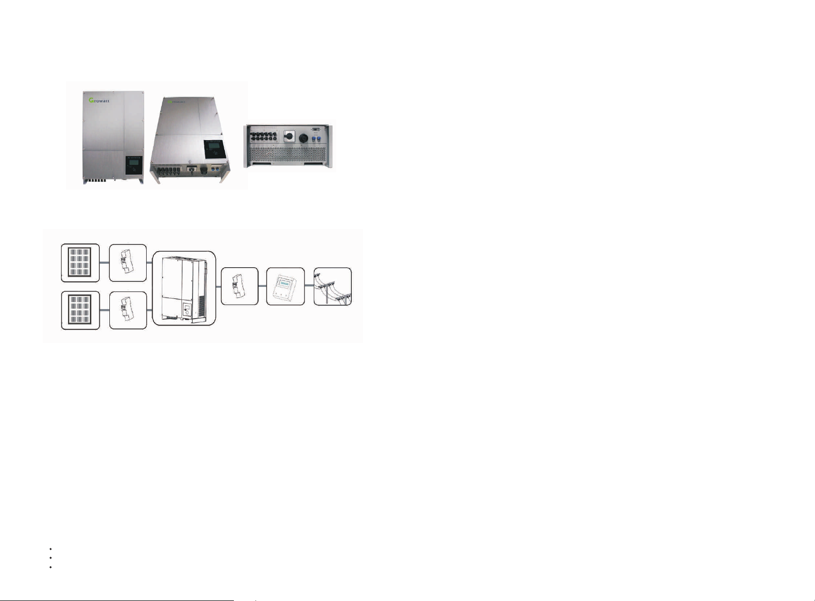
Inverters Overview:
DANGER!
Danger to life due to high voltages in the inverter!
All work on the inverter may be carried out by qualified personnel only.
The appliance is not to be used by children or persons with reduced physical, sensory
or mental capabilities, or lack of experience and knowledge, unless they have been
given supervision or instruction.
Children should be supervised to ensure that they do not play with the appliance.
Grid-tied PV system Overview:
Inp ut A
Inp ut B
As drawings shown above, a complete Grid-tied PV system consists of PV modules,
PV inverters, public grid and other components. Moreover, PV inverters always act as
key components.
When design a PV system contains Growatt UE series inverters or any other Growatt
inverters, the system designing software ShineDesign (download from site:
www.ginverter.com) will provide adequate supports.
: If PV modules of the PV system require POSITIVE or NEGATIVE GROUND, or the
Notes
capacity relative to ground of the modules is large, please contact Growatt New
Energy for technical support before installation.
DC Br eaker
DC Br eaker
GRO WATT UE Inv erter
AC Br eaker
Ene rgy met er
Pub lic gri d
CAUTION!
Danger of burn injuries due to hot enclosure parts!
During operation, the upper lid of the enclosure and the enclosure body may become
hot.
Only touch the lower enclosure lid during operation.
CAUTION!
Possible damage to health as a result of the effects of radiation!
Do not stay closer than 20 cm to the inverter for any length of time.
Grounding the PV generator
Comply with the local requirements for grounding the PV modules and the PV
generator.
Growatt recommends connecting the generator frame and other electrically
conductive surfaces in a manner which ensures continuous conduction and ground
these in order to have optimal protection of the system and personnel.
1.4 Safety
Growatt UE is designed to use worldwide, hence the inverters meet different safety
standards of variety countries and regions:
VDE0126-1-1
AS4777
Dk5940
CAUTION!
Possible damage the PV modules as a result of Identification
of String Failure!
The GROWATT UE Inverter is equipped with a system which recognizes total failure of
individual strings or part-strings.
Unpacking 2
A
B
C
D
E
F
2.2 Information of Label
2.1 Unpacking and Inspection
Before opening the packing box of Growatt UE, please note that whether there are
any visible external damages.
Once open the packing box, please check the delivery for completeness and for any
visible external damages of the inverter. If there are anything damaged or missing,
please contact your dealer. Complete delivery should contain as follows:
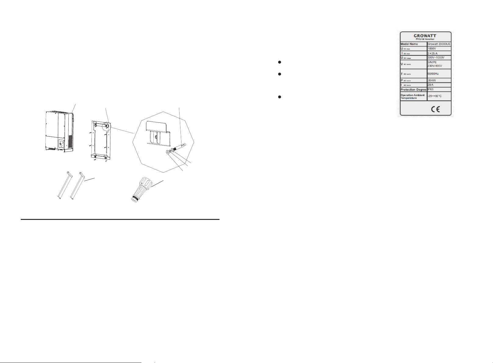
G
Description
Growatt UE inverter
Mounting frame
Expansion bolt
Screw washer
Spring washer
Nut
Handle
AC connector
User manual (not shown in the picture)
Number
1
1
6/8
6/8
6/8
6/8
2
1
1
Item
A
B
C
D
E
F
G
H
__
Hint: Number of C/D/E/F is 6 for Growatt 10000/12000UE, and 8 for Growatt 18000/20000UE.
H
The label contains information as below:
The inverter type/model (Model Name);
The certificates and approvals (Certificate
Number and Logos at the bottom of the
label);
Specifications of the inverter (From UDCmax
to Operation Ambient Temperature.
3 Mounting
3.1 Selecting Mounting Location
This is guidance for installer to choose a suitable installation location, to avoid
potential damages to device and operators.
The wall selected to install the inverter must be strong and firm
A
B
C
D
enough to support and bear the weight of the inverter for a long
period time. (Refer to Chapter 10 Specifications)
The location selected must be suitable for inverters’ dimension.
(Refer to 3.2 Dimensions and Required Clearances)
Do not install the inverter on structures constructed of flammable
or thermolabile materials.
Never install the inverter in environment of little or no air flow, nor
dust environment. That may derate the efficiency of the cooling fan
of the inverter; hence derate the efficiency of PV inverter.The
cooling fans and air grills should be cleaned every half or a year.
Notes
: Though the packaging box of Growatt UE is durable, please treat the packing
box gently and avoid dispose the packing box.
E
The Ingress Protection rate is IP65 which means the inverter can be
installed outdoors and indoors.

F
G
Do not expose the inverter to direct sunlight, in order to avoid the
power and efficiency derating caused by excessive heating.
The humidity of the installation location should be 0~95%
without condensation.
3.2 Dimensions and Required Clearances
Dimensions and weight :
Types
Height(H) Width(W)
Depth(D)
Weight/kg
H
I
J
K
The ambient temperature of the inverter should be -25℃~+60℃.
The installation location must be freely and safely to get at all
times.
Vertically installation and make sure the connection of inverter
must be downwards. Never install horizontal and avoids forward
and sideways tilt.(Refer to drawings below)
Notice the minimum clearances of the inverter. (Refer to 3.2
Dimensions and Required Clearances).
10000UE
12000UE
18000UE
20000UE
However, additional clearances are needed to guarantee running and operation of
the inverters. Especially when several inverters are installed together, the clearances
between the inverters and objects are necessary.
740
740
740
740
440
440
520
520
235
235
235
235
41
41
60
60
L
M
N
Do not install the inverter near television antenna or any other
antennas and antenna cables.
Do not install the inverter in living area, the noise caused by the
machine may affect on daily life.
For security reasons, DON’T install the inverter in place where the
children can reach.
3.3 Mounting the Bracket
To mount the inverter on the wall, we should mount the bracket to the wall firmly
first of all.
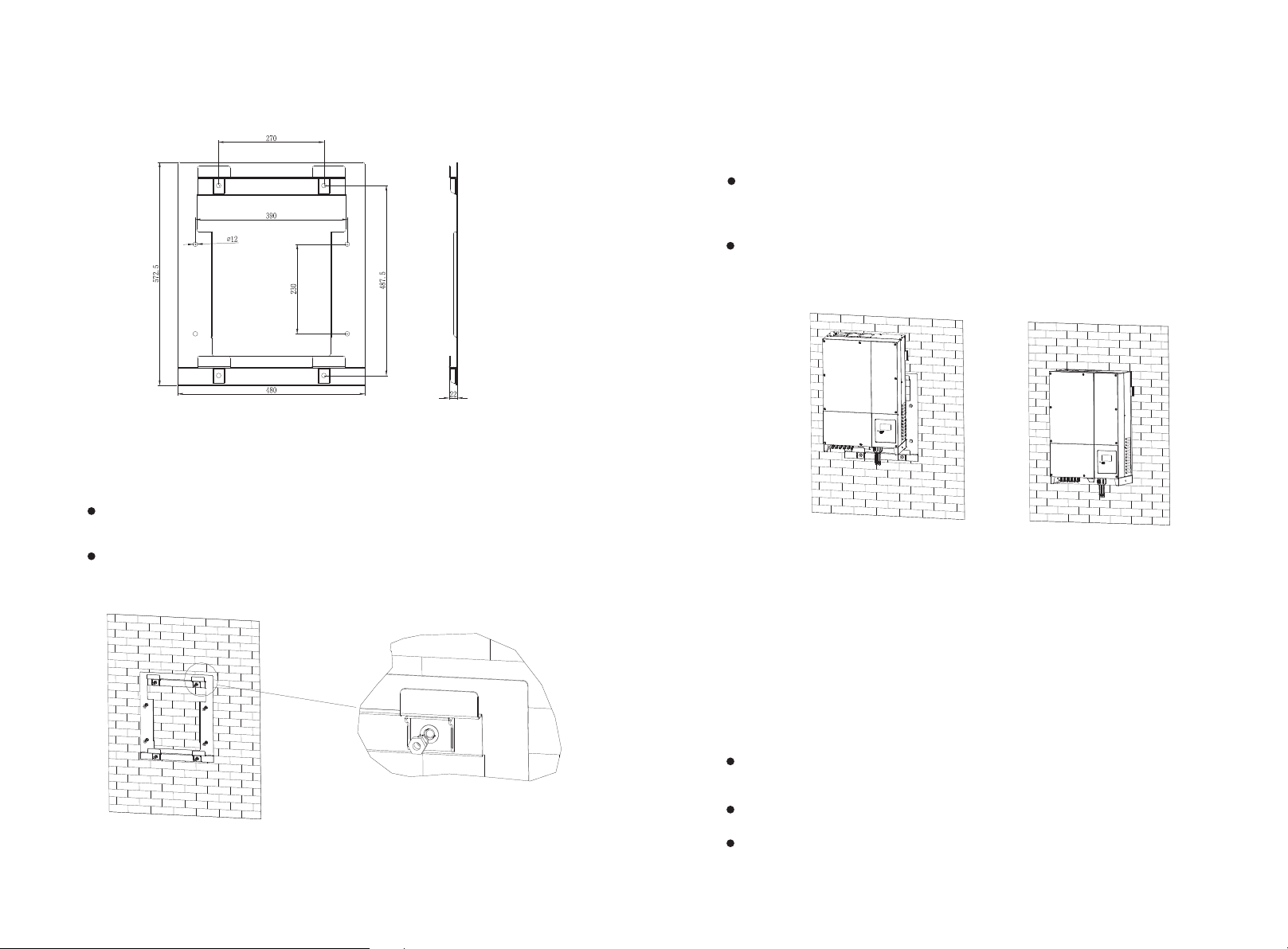
Overview of the Bracket:
Hint: Data units in mm
Steps:
Drill holes for screws while use the mounting frame as template.6 holes for
Growatt 10000/12000UE and 8 for Growatt 18000/20000UE.
Fix the mounting frame on the wall as the figures shown below, combine as
the screws as the Items overview picture shows (items C, D, E, F).
3.4 Mounting Inverter
After the bracket is firmly mounted on the wall, then mount the inverter on the bracket.
Rise up the Growatt UE a little higher than the bracket. Considered the weight of
Growatt UE, you need handles (items G shown in chapter 2.1) to hang on the
inverter. During the process please maintain the balance of the Growatt UE.
Hang the inverter on the bracket through the match hooks on bracket and the
back of the inverter.
: Never mount the inverter on the bracket unless you are sure that the
Notes
mounting frame is really firmly mounted on the wall after carefully checking.
4Electrical connections
4.1 Wiring AC Output
Measure the public grid voltage and frequency (Voltage: 400Vac;
Frequency: 50Hz/60Hz; in 3-Phase);
Open the breaker or fuse between the PV inverter and utility;
Screw torsional force is 8 kg/cm;
Spe cific ation o f AC breaker : Growatt 10000U E/ 12 000UE : 32A/4 00V
*
Growat t 180 00UE/ 2 0000U E: 63A/ 400V
*
Cable requirements:
Model
10000UE
12000UE
18000UE
20000UE
_(mm)
_2.05
_2.05
_2.59
_2.59
The interface of the connector:
E
1
2
Area(mm²)
3.332
3.332
5.260
5.260
N
AWG no.
12
12
10
10
3
5
Notes
: The connector must be screwed firmly. Before you operating and wiring the
AC output, please make sure that the AC breaker has been turned off (open).
: Detailed information of the connector refer to the manual of the connector in
Notes
package.
4
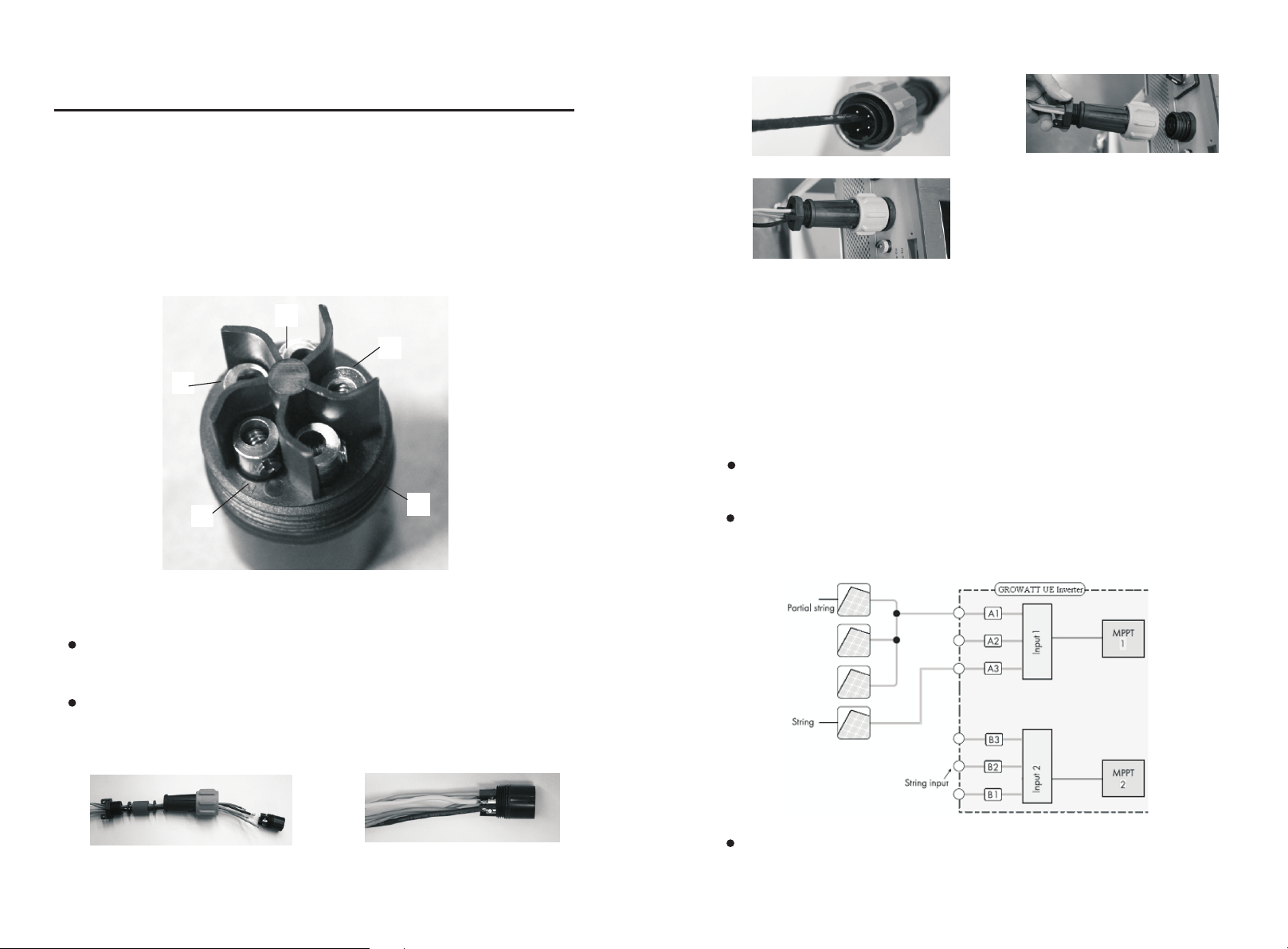
4.2 Wiring DC Input
The open circuit voltage of each string should never exceed 1000Vac, while the
length must be less than 30m;
3
The diagram drawing of DC side is shown as below, notice that the connectors
are in paired (male and female connectors). The connectors for PV arrays and
inverters are MC (multi-connector) connectors;
Connect cables to relative bolts shown in figure above , specifications of cables
must meet the requirements shown in the table above;
Assemble the connector as figures shown below;
1
2
Connect the positive and negative terminals from the PV panels to positive and
negative terminals on the PV inverter. The maximum string currents are varying
from different inverter types
 Loading...