

Growatt 10000HY Installation & Operation Manual

GROWATT NEW ENERGY TECHNOLOGY Co.,LTD
+ 86 755 2747 1900
+ 86 755 2747 2131
info@ginverter.com
www.ginverter.com
T
F
E
W
Growatt 10000HY
Installation
&
Operation Manual
No. 2 8 Gua ngmin g Road , Shi yan, Ba oan Dis trict ,
She nzhen , P.R. Ch ina
GR-UM-A03-A-00
Unpac kin g & Ove rvi ew
Installa tio n
Contents
1
3
4
Introduc tio n
Importan t Saf ety
War nin g
2
Grid (Util ity )
Conne cti on
5
3 1 Packing List
3 2 Pro du ct O ve rv ie w
.
.
4.1 Selecting Mounting Location
4.2 Mounting Unit
5.1 Pre pa ra ti on
5.2 Connecting to the AC Utility
PV Module (D C)
Conne cti on
6
Battery Co nne cti on
7
Load (A C Out put )
Conne cti on
8
8.1 Pre pa ra ti on
8.2 Connecting to the AC output
Dry Con tac t Sig nal
10
9
10.1 Electric Parameter
10.2 Function Description
Commu nic ati on
Relay C ont rol P ort
11
11.1 Interface Configuration
11.2 Function Description
11.3Application
Appli cat ion w ith
Energ y Met er
12
Commi ssi oni ng
13
Initial Se tup
14
Operatio n
15
15.1 Interface
15.2 LCD Information Define
15.3 Button Definition
15.4 Query Menu Operation
15.5 Operation Mode & Display
Charg ing
Manag eme nt
16
Maintena nce &
Clean ing
17
Tro ubl e Shootin g
18
Speci fic ati ons
19
18.1 Wa rn in g Li st
18.2 Fault Refere nc e Co de s

1 Introduction
This hy br id PV inve rt er ca n pro vi de power t o connected l oa ds by util iz in g P V power,
utility power and battery power.
21
WARN ING !
in s tr u ct ion s an d ca uti on ary mar k in gs on th e in ver te r a nd all
appro pr ia te s ec ti on s of t hi s gu id e.
Be f or e ins t al lin g an d u sin g th is inve rte r, re ad al l
Important Safety Warning 2
Before using t he i nv er te r, pl ea se rea d a ll i ns tr uc ti on s and c au ti on ar y markings on t he
unit and this manual. Store t he m an ua l wh er e it c an b e ac ce ss ed e as il y.
!
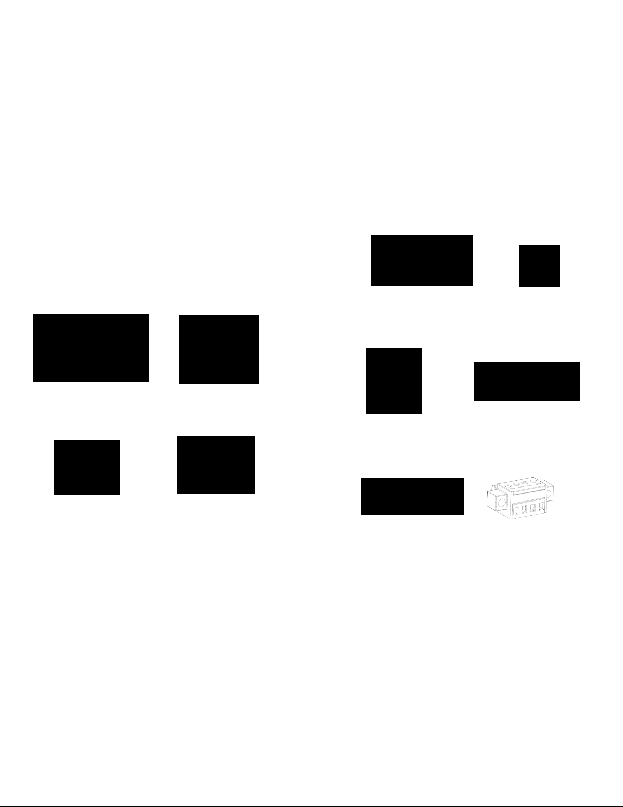
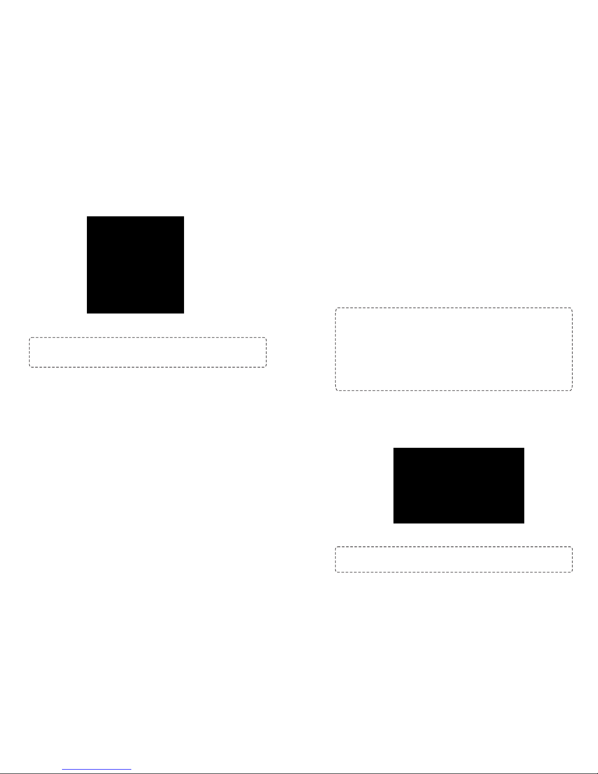
Hybrid inverter
PV module
Battery
Distribution Box
Load
Electric grids
Fig ure 1.1 B as ic hy brid PV S ystem O verv iew
Depending on d if fe rent p ow er s it ua ti on s, this h yb ri d in ve rt er is d es ig ne d to ge ne ra te
continuous po we r fr om P V so la r mo du le s (solar panels), bat te ry, a nd the utility.
When M PP in pu t v ol ta ge of PV modules is wi th in ac ce pt ab le ra ng e ( se e s pe ci fi ca ti on
for t he deta il s) , th is inve rt er is a bl e to gene ra te powe r to feed the gr id (uti li ty ) an d
charge b at te ry. Th is inverter i s on ly c om pa ti bl e with PV m od ul e ty pe s of si ng le
crystalline a nd poly crys ta ll in e. Do n ot conn ec t an y PV arra y ty pe s ot he r th an thes e
two type s of PV mo du le s to the inve rt er. Do not conn ec t the pos it iv e or nega ti ve
terminal of the sola r pane l to the ground. See Figu re 1 fo r a s im pl e diagram of a
typical solar system with this hybrid inverter.
Note:
allowed to charge ba tt er y fro m Utility. Th e relevant f un ct io n is a ut om at ic al ly d is ab le d
by the software .
By fo ll ow in g th e EE G standard, e ve ry i nv er te r sold to G er ma n are a is n ot
This man ua l is fo r qual if ie d pers on ne l. The task s desc ri be d in th is manual may be
performed by qualified personnel only.
General Pre ca ut io n
Conventions used:
WAR NI NG ! War ning s id en ti fy cond it io ns o r pr ac ti ce s t ha t co ul d re su lt in
personal injury;
CAUTION! Caution i de nt if y c on di ti on s o r p ra ct ic es that coul d r es ul t i n
damaged to the unit or other equipment connected.
WAR NI NG !
energized when a grou nd f au lt i s in di ca te d.
Normally gr ou nd ed co nd uc to rs m ay be u ng rounded and
!
WAR NI NG !
persons.
This inv er te r is hea vy. It sho ul d be lif te d by at lea st tw o
!
CAUTION!
electrical sh oc k by disconnecting AC , DC an d ba tt er y po we r f ro m
the inv er te r be fo re at te mp ti ng any ma in te na nc e or cleaning or
working on a ny circu it s connected t o th e inverter. Turn in g of f
control s will not redu ce th is ris k. In te rn al capacitors can rem ai n
charged for 5 minutes after disconnecting all sourc es o f po we r.
Authorized se rv ic e pe rs on ne l s ho ul d reduce th e ri sk of
!
CAUTION!
user-serviceable pa rt s. A tt em pt t o service t hi s in ve rt er y ou rs el f
may cause a r is k o f e le ct ri ca l s ho ck or f ire and wi ll vo id th e
warranty from t he m an uf ac tu re r.
Do n ot disassemble th is inverter y ou rs el f. It c on ta in s no
CAUTION!
existing wi ri ng is in g oo d c on di ti on and th at th e wi re is no t
unde rs iz ed . Do no t ope ra te the In ve rt er with dam ag ed or
substandard w ir in g.
To avo id a ri sk of fire a nd e le ct ri c s ho ck , make su re t ha t
CAUTION!
inverter could b e ho t en ou gh t o ca us e sk in b ur ns i f ac ci de nt al ly
touched. Ensure t ha t th is i nv er te r is a wa y fr om n or ma l tr affic are as .
Under hi gh te mp er at ur e e nv ironment, th e c ov er of th is
CAUTION!
Otherwise, no t- qu al if ie d to ol s may cau se a risk of fi re, ele ct ri c
shock, or injury to persons.
Use o nl y reco mm en de d a cc es so ri es fro m inst al le r.
CAUTION!
cooling fan.
To r ed uc e risk of fi re haza rd , do n ot cov er or ob st ru ct the
!
CAUTION!
been dr op pe d, o r oth er wise dam ag ed i n an y way. If the I nv er te r is
damaged, please call for an RMA (Retur n Ma te ri al A ut ho ri za ti on ).
Do not operate the In ve rt er if it ha s received a sh ar p b lo w,
!
CAUTION!
as d is co nn ec t d ev ic es an d t he se di sc on ne ct de vi ce s s ha ll be ea si ly
accessible.
AC br ea ke r, DC sw it ch an d Battery circu it br ea ke r are u se d
Before wo rk in g on t hi s ci rc ui t
-Isolate inverter/Uninterruptible Power System (UPS)
-Then check for Hazard ou s Vol ta ge b et we en a ll t er mi na ls i nc lu di ng
the pro te ct iv e ea rt h.
Risk of Voltage Backfeed
Symbols used in Equipment Markings
!
Refer to the operating instructions
Caution! Risk of danger
Caution! Risk of electric shock
Caution! Risk of electric shock. Energy storage timed
discharge for 5 minutes.
Caution! Hot surface
Table 2 .1
3 4
5 6
3 Unpacking & Overview
3.1 Pa cki ng List
Before in st al la ti on , please in sp ec t th e un it . Be su re tha t no th in g in si de t he package is
damaged. You s ho ul d ha ve received the following items inside of package:
Inverter unit PV connectors
AC connector
Mounting plate
Fixing scre ws
Software CD
Manual
USB cable
RS-232 cable
Relay control p or t
Fig ure 3.1

7
8
Installation 4
4.1 Se lec ting Mo unt ing Loc ati on
Consider the following points before se le ct in g wh er e to i ns ta ll :
Do not mount the inverter on flammable construction materials.
Mount on a solid surface
This inverter can m ak e no is es d ur in g op er at io n wh ic h ma y be p er ce iv ed a s a
nuisance in a living area .
Install t hi s inverter at eye l ev el in orde r to al lo w th e L CD disp la y to be read at all
times.
For p ro pe r a ir circ ul at io n t o di ss ip at e heat, a ll ow a clearance o f ap pro x. 20 c m t o
the side and approx . 50 c m ab ov e an d be lo w th e un it .
Dusty conditions on the unit may impair the performance of this inverter.
The a mb ie nt te mp er at ur e should be between 0° C a nd 40°C an d relative hu mi di ty
should be between 5% and 85% to ensure op ti ma l op er at io n.
The rec om me nd ed i ns ta ll at io n po si ti on i s to b e ad he re d to v er ti ca l.
For prop er op er at io n o f t hi s i nv er te r, p le as e u se ap propriate c ab le s f or gr id
connection.
The po ll ut io n degree of t he in ve rt er is P D2 . S el ec t an ap propriate mo un ti ng
location. In st al l th e so la r in ve rt er in a p rotected a rea th at i s dr y, fre e of ex ce ss iv e du st
and ha s adequate ai r f lo w. Do NO T op er ate i t where t he t em pe ra tu re and hu mi di ty is
beyond the specific limits. (Please check the specs for the limitations.)
Installation position shall not pre ve nt a cc es s to t he d is co nn ec ti on m ea ns .
This inverter is designed with IP20 for indoor applications only.
Regularly clean the fan filter.
·
·
·
·
·
·
·
·
·
·
·
·
·
Installation to the wa ll sho ul d be imp le me nt ed with th e prope r scre ws . Af te r that ,
the device should be bolted on secure ly.
The inv er te r only ca n be us ed i n a CLO SE D ELE CT RI CA L OP ER ATI NG AR EA . On ly
service person can enter into this area .
1) PV connectors
2) AC Grid connectors
3) Battery connectors
4) AC output connectors
(Load connection)
5) RS-232 communication port
6) USB communication port
7) Intelligent slot
8) Grou nd in g
9) LCD display panel (Please check section
10 for detailed LCD operation)
10) Operation buttons
11) Dry contact
12) Battery thermal sensor
13) EPO
14) AC circ ui t br ea ke r
15) DC Switch
16) Relay control p or t
WAR NI NG !!
out fro m th e pa ck ag e.
Remember that th is in ve rt er is he av y! Pl ea se be care fu ll y w he n l if ti ng
4.2 Pr epa ratio n
WAR NI NG !!
SU ITA BLE FO R M OU NTIN G ON C ON CR ETE OR OT HER NO N- COM BU STI BL E
SURFACE ONLY.
FIRE HAZARD.
3.2 Pr odu ct Over vie w
Fig ure 3.2

9
10
1. Drill six ho le s in the ma rk ed lo ca ti on s wit h sup pl ie d six scre ws . The re fe re nc e
tightening torq ue i s 35 N .m .
3. Fi x th e in ve rt er in po si ti on by s crewing t he supp li ed two screw s (M 4* 12 ) lo ca te d
on the top two sides of the inverter.
2. Raise the inverter and place it over the mounting plate.
4. Check if the inverter is firmly secure d.
Fig ure 4.1
Fig ure 4.2
Fig ure 4.3
Fig ure 4.4
11
12
5 Grid (Utility) Connection
5.1 Pr epa ratio n
NOTE:
power distribution.
NOTE2: The in ve rt er is b ui lt in a 25A/ 40 0V brea ke r to prot ec t th e in ve rt er from AC
power damage.
The o ve rv ol ta ge ca te go ry of th e AC in pu t i s II I. It should be co nn ec te d to th e
WAR NI NG !
appro pr ia te cabl e fo r gr id (utility) connection. To re du ce risk of injury, p le as e use
the pro pe r re co mm en de d ca bl e si ze a s be lo w.
It's very im po rt an t for sy st em sa fe ty an d eff ic ie nt op er at io n to use
Suggested cable req ui re me nt f or A C wi re
Nominal Grid Voltage
Conductor cro ss -s ec ti on ( mm 2)
AWG n o.
230VAC per phase
10-16
8-6
5.2 Co nne cting t o the A C Utili ty
Overview of AC Connection Socket
A
B
C
D
E
Component
A
B
C
D
E
Description
Pre ss ur e do me
Clip
Sealing nut
Pro te ct iv e el em en t
Socket element
Step 1: Check t he gr id vo lt ag e a nd fr eq ue nc y w it h a n A C v ol tm et er. It should be th e
same to “VAC” value on the pro du ct l ab el .
Step 2: Turn o ff t he c ircuit brea ke r.
Step 3: Remove insulation sleeve 13 mm for five conductors.
Step 4 : Th re ad t he five c ab le s th ro ug h pr es su re d om e (A), cl ip ( B) , sealing n ut ( C) an d
pro te ct iv e el em en t (D ) in s eq ue nc e.
Step 5: Th rea d five cables t hro ug h socket el em en t (E ) ac co rding to p ol ar it ie s
indicated on it and tighten the screw s to f ix w ir es a ft er c on ne ct io n.
L1→ LINE 1 (Black)
L2→ LINE 2 (Grey)
L → LINE 3 (Brown)
→ Ground (Yell ow -G re en )
N → Neutral (Blue)
The ref er en ce t ig ht en in g to rque is 1.5-2.5 N.m.
Step 6: Pu sh protective do me (D ) on to soc ke t ele me nt (E) until bot h are lo ck ed
tightly. The n, t wi st p rotective element (D) and pre ss ur e do me ( A) s o th at a ll c ab le s ar e
firmly connected.
Fig ure 5.1
Fig ure 5.2
Fig ure 5.3
Fig ure 5.4
Table 5 .1
Table 5 .2
13
14
Step 7: Plug the AC connection socket into AC grid terminal of the inverter.
CAUTION:
earthed b ef or e operating t hi s hy br id inverter n o ma tt er the gr id is co nn ec ted or
not.
To p re ve nt ris k of electric shoc k, ens ur e the groun d wire is prope rl y
PV Module (DC) Connection 6
CAUTION:
bre ak er b et we en i nv er te r an d PV m od ul es .
NOTE1: Please use 1000VDC/20A circu it b re ak er.
NOTE2: The overvoltage category of the PV input is II.
Before connecting to PV mod ul es , plea se ins ta ll separately a DC cir cu it
Please follow below steps to implement PV module connection:
WAR NI NG :
are ac ce pt ab le : s in gl e crystalline and po ly cr ys ta ll in e w it h c la ss A-rated an d C IG S
modules.
To avoid any malfunction, do no t con ne ct an y PV mod ul es wi th po ss ib il it y of
leakage current to the inve rt er. For exa mp le , grou nd ed PV mod ul es wi ll cau se
leakage cu rrent to the inve rt er. When usin g CI GS mod ul es , pl ea se be su re NOT
gro un di ng .
CAUTION: It’s r eq ue st ed to have PV junc ti on box wit h surg e prot ec ti on .
Otherwise, it will cause inverter damage when lightning occurs on PV modules.
Because t hi s in ve rt er is no n- is ol at ed , on ly three type s of PV m od ul es
Step 1 : Ch ec k the i np ut v ol ta ge of P V array m od ul es . Th e a cc ep ta bl e in pu t voltage o f
the i nv er te r i s 35 0V DC - 900VDC. T hi s s ys te m is on ly applied w it h t wo stri ng s o f PV
array. Please m ak e s ure th at the ma xi mu m c ur rent l oa d o f ea ch PV input co nn ec to r i s
18.6A.
CAUTION:
the system before w ir e co nn ec ti on .
Exceeding th e maxi mu m inpu t volt ag e can dest roy th e unit !! Che ck
Fig ure 5.5
Fig ure 6.1
S te p 3: Asse mb le pr ov id ed PV connectors w it h PV modu le s by th e fo ll ow in g be lo w
steps.
Components for PV connectors and Too ls :
Female connector housing
Female terminal
Male connector housing
Male terminal
Crimping tool and spanner
Cable preparation and connector assembly process:
Strip one cable 8 mm on both end sides and be
caref ul N OT t o ni ck c on du ct or s.
Insert striped cable into female terminal and
crimp female terminal as shown below charts.
Insert assembled cable into female connector housing as shown below charts.
Insert striped cable into male terminal and crimp male terminal as shown below charts.
Insert assembled cable into male connector housing as shown below charts.
Then, use spa nn er to sc rew pres su re do me tightly to fema le co nn ec to r and ma le
connector as shown below.
Step 2: Disconnect the circ ui t br ea ke r an d sw it ch o ff the DC switch.
Step 4: Check correc t pola ri ty of conn ec ti on cab le fro m PV mo du le s and PV in pu t
connectors. T he n, conn ec t po si ti ve pole (+) o f co nn ec ti on cabl e to positive po le (+)
of PV input conn ec to r. Con ne ct n eg at iv e po le ( -) o f co nn ec ti on c able to negative p ol e
(-) of PV input connector.
WAR NI NG !
appro pr ia te cable f or PV modu le co nn ec ti on . To re du ce ri sk of in ju ry, pl ea se us e the
pro pe r re co mm en de d ca bl e si ze a s be lo w.
It's v er y i mp or ta nt fo r s ys te m s af et y and e ff ic ie nt op er at io n t o use
Fig ure 6.2
Fig ure 6.3
Fig ure 6.4
Fig ure 6.5
Fig ure 6.6
Fig ure 6.7
Table 6 .1
15
16
 Loading...