


SERIES 200
MIXER OWNER'S MANUAL

4310 N. 126th Street, Brookfield, WI 53005
Phone (262) 781-5020 Fax (262) 781-8120
TABLE OF CONTENTS
About this Manual.......................................................................................................... 2
Read this Owner's Manual Prior to Using Your Grovhac Mixer..............................2
Important Safety Terminology.................................................................................. 2
Mixer Installation............................................................................................................. 3
Handling...................................................................................................................... 3
Mounting..................................................................................................................... 3
Set-up.......................................................................................................................... 4
Mixers with Air Motors....................................................................................................... 4
Mixers with Electric Motors............................................................................................... 4
Before Operating Your Grovhac Mixer....................................................................... 5
Operating Your Grovhac Mixer.................................................................................... 6
Mixers with Air Motors....................................................................................................... 6
Mixers with Electric Motors............................................................................................... 6
Mixer Maintenance....................................................................................................... 7
Motor Maintenance & Service................................................................................. 7
Air Motors.......................................................................................................................... 7
Electric Motors.................................................................................................................. 8
Removing the Mixer's Motor..................................................................................... 9
Direct Drive Mixers............................................................................................................ 9
Tools and Materials Required................................................................................................... 9
To Remove the Motor............................................................................................................... 9
To Replace the Motor............................................................................................................... 9
Gear Drive Mixers........................................................................................................... 10
Tools and Materials Required................................................................................................. 10
To Remove the Motor............................................................................................................. 10
To Replace the Motor............................................................................................................. 10
Gear Box Maintenance & Service......................................................................... 10
Removing the Mixer's Gear Box..............................................................................11
Tools and Materials Required................................................................................................. 11
To Remove the Gear Box....................................................................................................... 11
To Replace the Gear Box....................................................................................................... 11
Notes............................................................................................................................. 13
1 www.grovhac.com

4310 N. 126th Street, Brookfield, WI 53005
Phone (262) 781-5020 Fax (262) 781-8120
ABOUT THIS MANUAL
Read this Owner's Manual Prior to Using Your Grovhac Mixer
Read all instructions prior to operating mixer. Injury to personnel, damage to property, or premature
equipment failure may occur if mixer is improperly installed or operated. Do not discard this manual;
keep this owner's manual for future reference.
Important Safety Terminology
Please see the following table regarding safety terminology used throughout this owner's manual. When
referring to this manual, read the information following each safety term carefully before proceeding.
Failure to follow the recommendations in this manual can result in personal injury or damage to
property.
SAFETY TERMS
Result if recommendations are ignored
DANGER Severe personal injury or death will occur if hazard is ignored.
Warning Severe personal injury or death can occur if hazard is ignored.
Caution Minor injury or property damage can occur if hazard is ignored.
2 www.grovhac.com
4310 N. 126th Street, Brookfield, WI 53005
Phone (262) 781-5020 Fax (262) 781-8120
MIXER INSTALLATION
Handling
Never lift a mixer by its shaft. Grovhac mixers & agitators should be handled by lifting only on the
gearbox or drive unit, while also carefully supporting the mixer shaft & blades.
Mounting
Mount your mixer on a level tank surface and fasten securely; your mixer may fasten using bolts,
threaded bung, or clamps. For C-Clamp mixers, never use tools to tighten clamp; hand tighten only.
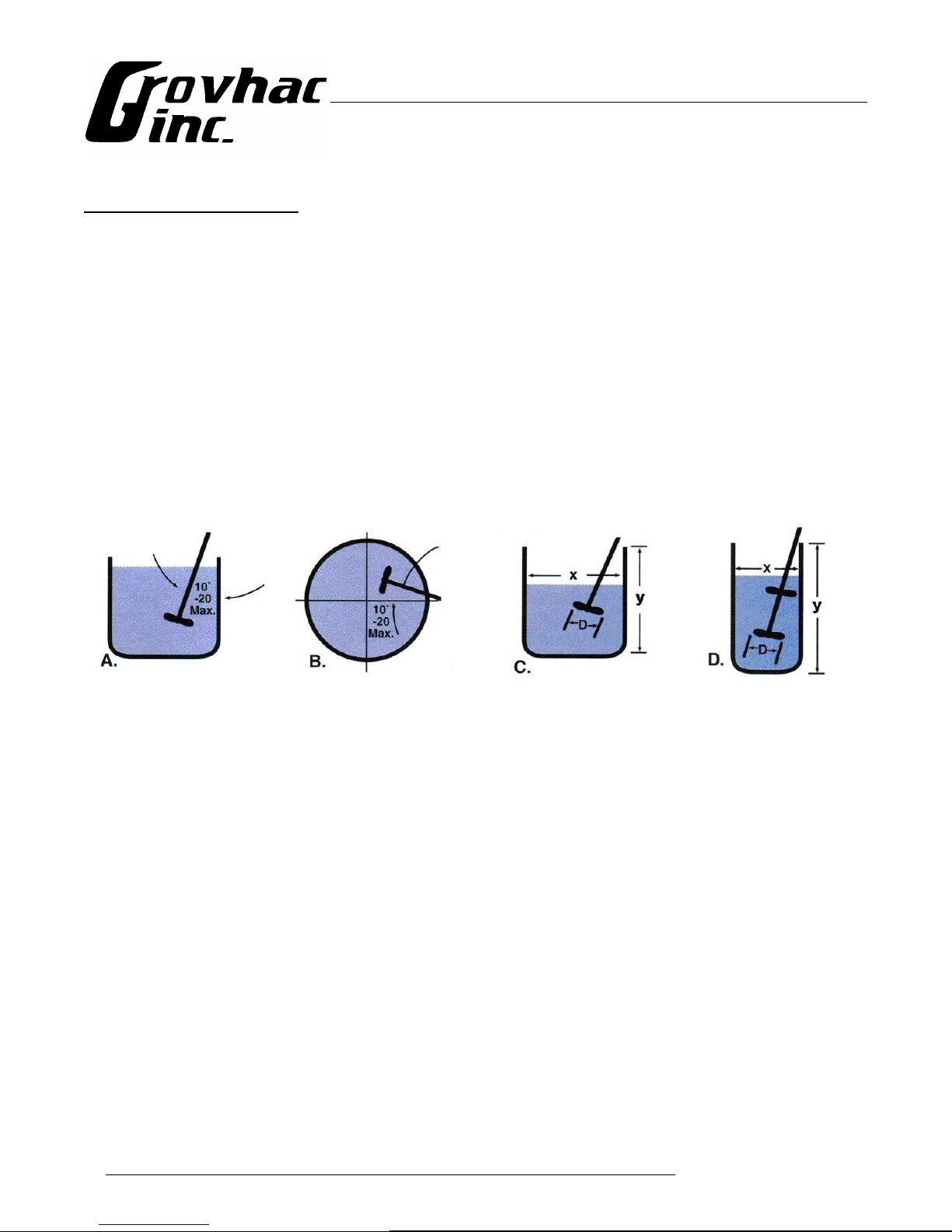
The following illustrations show recommendations for mounting mixers and number of propellers
required.
For proper mixing action in tanks without baffles, mixer
shafts should be mounted 10º to 20º off vertical and 10º to
20º off the tank center line, as shown in Illustrations A & B.
If the depth of the liquid (y) is approximately equal to the
diameter of the tank (x), a single propeller may be used, as
shown in Illustration C. Dual propellers are usually
specified when the liquid depth (y) is 1.5 times (or greater)
the diameter of the tank (x), as shown in Illustration D. The
bottom propeller should be placed 1 to 2 propeller
diameters from the bottom of the tank.
3 www.grovhac.com

4310 N. 126th Street, Brookfield, WI 53005
Phone (262) 781-5020 Fax (262) 781-8120
Set-up
Mixers with Air Motors
Install your air motor using air lines the same size or the next size larger than the intake port of the
motor.
It is recommended that you install a moisture trap and filter/lubricator in the air line ahead of the motor.
Excessive moisture in the air line can cause rust formation in the motor and might also cause ice to form
on the muffler (due to expansion of air through the motor). Lubrication is necessary for the bearings,
shaft seals, and to prevent rust formation.
Note: allowing excess moisture or foreign particles from the air line to enter the motor will nullify any
warranties.
If operating the motor intermittently without automatic air line oiler, place motor in accessible position
for easy lubrication.
A non-reversing motor will operate properly in one direction only; a reversible motor will work equally
well in both directions; all Grovhac mixers are designed to run clockwise when viewed from the top of
the motor.
When coupling or connecting the motor to a driven member, avoid any end or side thrust and never
hammer on the shaft.
Mixers with Electric Motors
For electric motors without electrical plugs, check local codes for wiring instructions.
Before making electrical power connections, check for proper grounding of motor and application. All
electrical contacts and connections must be properly insulated and enclosed. Prior to connecting to the
power line, check nameplate for proper voltage and rotation connection. All Grovhac mixers are
designed to run clockwise when viewed from the top of the motor.
Caution: Your electric motor should be installed in compliance with the National Electric Code,
OSHA, and any other applicable codes, Voltage at motor not to exceed + or – 10% of nameplate
voltage. Authorized person should make all electrical connections.
Motor should be located in a clean and dry area with adequate ventilation. Motor must be protected from
the weather, if installed outdoors.
Warning: use only explosion-proof motors for applications with explosive gases or materials
present.
4 www.grovhac.com

4310 N. 126th Street, Brookfield, WI 53005
Phone (262) 781-5020 Fax (262) 781-8120
BEFORE OPERATING YOUR GROVHAC MIXER
✔ Remove all packaging materials, especially those fastened to the mixing equipment for transit.
✔ Always make sure mixer is properly supported.
✔ Always place mixer shaft in liquid before operating.
✔ Never use for flammables or combustibles without having an approved explosion-proof motor.
✔ Always properly ground mixer when mixing flammables or combustibles.
✔ Always wear protective clothing, eyewear, and follow standard safety procedures.
5 www.grovhac.com

4310 N. 126th Street, Brookfield, WI 53005
Phone (262) 781-5020 Fax (262) 781-8120
OPERATING YOUR GROVHAC MIXER
Mixers with Air Motors
Your air motor is a precision built rotary-type motor and is designed to be driven by compressed air
only. The air motor must not be driven by fluids, particles, solids, or any substance mixed with air,
particularly combustible substances likely to cause explosions.
Warning: solid or liquid material exiting the air motor can cause eye or skin damage – keep away
from air stream.
Warning: some air motor models may exceed 85dB sound level – hearing protection is
recommended.
The stalled or starting torque of your air motor is less than the running torque and will vary depending
on the position at which the vanes stop in relation to the air intake port. Operate motor well below
available line pressure so that full line pressure can be called upon for overloads on motor. The speed
and torque can be regulated by using a pressure regulator or a simple shut-off valve.
Caution: do not allow the air motor to "run free" at high speeds with no loads – excessive internal
heat build-up, loss of internal clearances, and rapid motor damage will result.
Mixers with Electric Motors
Warning: be careful when touching the exterior of an operating motor – it may be hot enough to
cause injury. Normal operating temperature of motor may be high enough to be uncomfortable or to
cause injury if touched.
6 www.grovhac.com

4310 N. 126th Street, Brookfield, WI 53005
Phone (262) 781-5020 Fax (262) 781-8120
MIXER MAINTENANCE
Motor Maintenance & Service
Air Motors
Warning: always disconnect the air supply before servicing.
Use SAE10 oil to lubricate your air motor. For moderate speeds or intermittent operation, one squirt of
oil in bearing oilers per day will suffice. If the duty is continuous or speed is high, use an automatic air
line oiler set to feed one drop per minute. The bearings will receive oil from the rotor chamber during
automatic oiling.
If the motor is sluggish or inefficient, try flushing with a non-combustible solvent. Always flush in a
well ventilated area. To flush with solvent, disconnect the air line and muffler and add several
teaspoons or spray solvent directly into motor. Rotate the shaft by hand in both directions for a few
minutes, re-connect the air line and apply pressure slowly until there is no trace of solvent in the exhaust
air. Warning: wear eye protection and keep face away from exhaust air – foreign material exiting
the air motor can be hazardous. Check the muffler felts or elements for grease, dirt, or other
contaminants. If dirty, wash them in a solvent. Replace the felts or elements and reconnect the muffler.
Re-lubricate the motor with a squirt of oil in the chamber and bearing oilers.
The motor's vanes take up their own wear and will last between 5,000-15,000 hours depending on speed,
method of oiling, operating pressure, and precautions taken in maintaining the motor. If the vanes need
replacing, or if foreign particles are present in the motor chamber, an experienced mechanic may remove
the end plate opposite the drive shaft end. Do not pry open with a screwdriver; prying will dent the
surface of the plate and body, which can cause leaks. A puller tool should be used which will remove the
end plate while maintaining the position of the shaft. New vanes should have the edge with the corners
cut on angle (notched edge if reversible air motor) towards the bottom of the vane slot. New gaskets
should be the proper thickness (similar to onion skin), otherwise the motor will operate inefficiently and
waste air. The end plates should be replaced carefully using an arbor press with a pusher acting on both
races of the bearing while supporting the opposite (drive) end of the shaft. This will eliminate the risk of
stress fatigue and misalignment of the rotor.
7 www.grovhac.com

4310 N. 126th Street, Brookfield, WI 53005
Phone (262) 781-5020 Fax (262) 781-8120
Please see the following chart for motor top clearance (between rotor and bore) and total end clearance
(between the sides of the rotor and the end plates).
AIR MOTOR CLEARANCE CHART
Models Total End Clearance (in / mm) Top Clearance (in / mm)
1101, 1111, 1111-15, 1UP 0.0020" / 0.0508mm 0.0015" / 0.0381mm
1102, 1302 0.0025" / 0.0635mm 0.0015" / 0.0381mm
1103, 1223, 1303 0.0035" / 0.0889mm 0.0015" / 0.0381mm
1104, 1224, 1304 0.0035" / 0.0889mm 0.0015" / 0.0381mm
1225, 1305 0.0048" / 0.1219mm 0.0015" / 0.0381mm
In many cases, it is quicker and more cost effective to send the motor back to the factory for repair. For
more information on air motor repairs, please contact your Grovhac representative.
Electric Motors
Warning: always disconnect the power source before working on or near a motor or its connected
load.
Warning: use approved non-explosive and non-flammable materials when cleaning electrical
equipment. Do not attempt to clean the motor while electrical power is connected.
Your electric motor is supplied with pre-lubricated ball bearings, lubricated for life of the bearing. Do
not attempt to lubricate the motor's bearings.
Direct current (DC) motors have motor brushes that need periodic inspection and replacement as wear
indicates. Brush wear is greatly influenced by individual application. It is recommended that brush wear
be checked at early intervals of operation in order to determine future required inspection. Standard
motor brushes have an initial length of 1¼". When the brushes are worn to a length of 5/8" they should
be replaced.
If mechanical or electrical failure occurs, first check for proper electrical connections, fusing, or unusual
binding of mechanical connections. If unable to correct the problem, please contact your Grovhac
representative, describe the problem, and include complete motor nameplate data.
8 www.grovhac.com

Removing the Mixer's Motor
Direct Drive Mixers
Tools and Materials Required
✔ 9/16" box wrench or adjustable wrench
✔ 5/8" box wrench or adjustable wrench
✔ 5/16" Allen wrench
✔ Two (2) 7/16"-14 bolts, approximately 3" long
✔ LOCTITE® or similar thread bonding agent
✔ Emery paper or similar light abrasive
4310 N. 126th Street, Brookfield, WI 53005
Phone (262) 781-5020 Fax (262) 781-8120
To Remove the Motor
1) Remove the four (4) 3/8"-16 x 1" bolts and lock washers that secure the motor's C-face to the
bearing housing.
2) Thread two (2) 7/16"-14 bolts (not supplied) into the 7/16" threaded holes of the bearing
housing face. Alternately tighten the two bolts to push the motor off the bearing housing
evenly (note: stainless steel shaft coupling will normally come off with motor)
3) Use a 5/16" Allen wrench to loosen the hollow set-screw in the shaft coupling. Remove the
shaft coupling.
To Replace the Motor
1) Clean the inside diameter of the bearing in the bearing housing. Clean the outside of the
stainless steel shaft coupling.
2) Remove the hollow set-screw and its set key from the shaft coupling.
3) Slide the shaft coupling onto the motor shaft. Align the hole in the shaft coupling with the
keyway on the motor shaft. Insert the set key into the hole of the shaft coupling while
aligning the keyway with the motor shaft. You may need a large screwdriver to adjust the set
key so it lines up with the motor shaft.
4) Place a few drops of LOCTITE or similar thread bonding agent on the threads of the hollow
set-screw. Thread the hollow set-screw into the coupling and fully tighten using a 5/16"
Allen wrench.
5) Slide the bearing housing assembly over the shaft coupling (note: due to close tolerances
and thread locking compound build-up, you may need to clean the shaft coupling with emery
paper or a similar light abrasive for it to fit inside the bearing).
9 www.grovhac.com

4310 N. 126th Street, Brookfield, WI 53005
Phone (262) 781-5020 Fax (262) 781-8120
6) Replace the four (4) 3/8"-16 x 1" motor bolts and lock washers, but do not yet fully tighten.
7) Start motor and, while the motor is running, alternately tighten the four (4) motor bolts until
they are secure (note: motor bolts must be tightened in this manner to ensure proper
alignment of the coupling and bearing housing components).
Gear Drive Mixers
Tools and Materials Required
✔ 9/16" box wrench, socket wrench, or adjustable wrench
✔ Small amount of light grease
To Remove the Motor
1) Remove the four (4) 3/8"-16 x 1" bolts w/ lock washers that secure the motor's C-face to the
bearing housing.
2) Slide the motor up and out of the gear box (note: ensure that the shaft key comes with the
motor).
To Replace the Motor
1) Place key in the motor shaft keyway. Lightly lubricate the motor output shaft and the keyway
with a light grease.
2) Slide the motor output shaft into the hollow shaft of the gear box (note: ensure that the key
stays on the motor shaft).
3) Align the holes of the gear box face with the holes on the motor C-face and replace the four
(4) bolts (3/8-16 x 1") w/ lock washers to secure the motor to the gear box.
Gear Box Maintenance & Service
Your Grovhac gear reducer has been tested and adjusted at the factory. Dismantling or replacement of
components will void the warranty.
The gear reducer is properly filled at the factory with sufficient lubricant for all mounting positions. The
reducer may be mounted in any supplier approved mounting position without modification or changing
oil level. The oil should be changed approximately every six (6) months or 2,300 hours; please see your
gear box's part sheet for instructions on changing gear box lubricant.
10 www.grovhac.com

Removing the Mixer's Gear Box
Tools and Materials Required
✔ 9/16" box wrench or adjustable wrench
✔ 5/8" box wrench or adjustable wrench
✔ 5/16" Allen wrench
✔ Two (2) 7/16"-14 bolts, approximately 3" long
✔ LOCTITE® or similar thread bonding agent
✔ Emery paper or similar light abrasive
To Remove the Gear Box
Note: Remove the mixer's motor from the gear box before attempting to remove the gear box
(see Removing the Mixer's Motor, Gear Drive Mixers, To Remove the Motor section).
4310 N. 126th Street, Brookfield, WI 53005
Phone (262) 781-5020 Fax (262) 781-8120
1) Remove the four (4) 3/8"-16 x 1" bolts and lock washers that secure the gear box's C-face to
the bearing housing.
2) Thread two (2) 7/16"-14 bolts (not supplied) into the 7/16" threaded holes of the bearing
housing face. Alternately tighten the two bolts to push the gear box off the bearing housing
evenly (note: coupling will normally come off with gear box)
3) Use a 5/16" Allen wrench to loosen the hollow set-screw in the shaft coupling. Remove the
shaft coupling.
To Replace the Gear Box
Note: Replace the mixer's motor on the gear box before attempting to replace the gear box (see
Removing the Mixer's Motor, Gear Drive Mixers, To Replace the Motor section).
1) Clean the inside diameter of the bearing in the bearing housing. Clean the outside of the
stainless steel shaft coupling.
2) Remove the hollow set-screw and its set key from the shaft coupling.
3) Slide the shaft coupling onto the gear box shaft. Align the hole in the shaft coupling with the
keyway on the gear box shaft. Insert the set key into the hole of the shaft coupling while
aligning the keyway with the gear box shaft. You may need a large screwdriver to adjust the
set key so it lines up with the gear box shaft.
4) Place a few drops of LOCTITE or similar thread bonding agent on the threads of the hollow
set-screw. Thread the hollow set-screw into the coupling and fully tighten using a 5/16"
Allen wrench.
11 www.grovhac.com

4310 N. 126th Street, Brookfield, WI 53005
Phone (262) 781-5020 Fax (262) 781-8120
5) Slide the bearing housing assembly over the shaft coupling (note: due to close tolerances
and thread locking compound build-up, you may need to clean the shaft coupling with emery
paper or a similar light abrasive for it to fit inside the bearing).
6) Replace the four (4) 3/8"-16 x 1" gear box bolts and lock washers, but do not yet fully
tighten.
7) Start motor and, while the motor is running, alternately tighten the four (4) gear box bolts
until they are secure (note: gear box bolts must be tightened in this manner to ensure proper
alignment of the coupling and bearing housing components).
12 www.grovhac.com

4310 N. 126th Street, Brookfield, WI 53005
Phone (262) 781-5020 Fax (262) 781-8120
NOTES
13 www.grovhac.com

Grovhac, Inc. Phone (262) 781-5020
4310 N. 126th Street Fax (262) 781-8120
Brookfield, WI 53005 USA www.grovhac.com
©2005 Grovhac, Inc.
 Loading...