

Grove Hill Audio LIVERPOOL Operating Instructions Manual
LIVERPOOL Tube Compressor Page 1
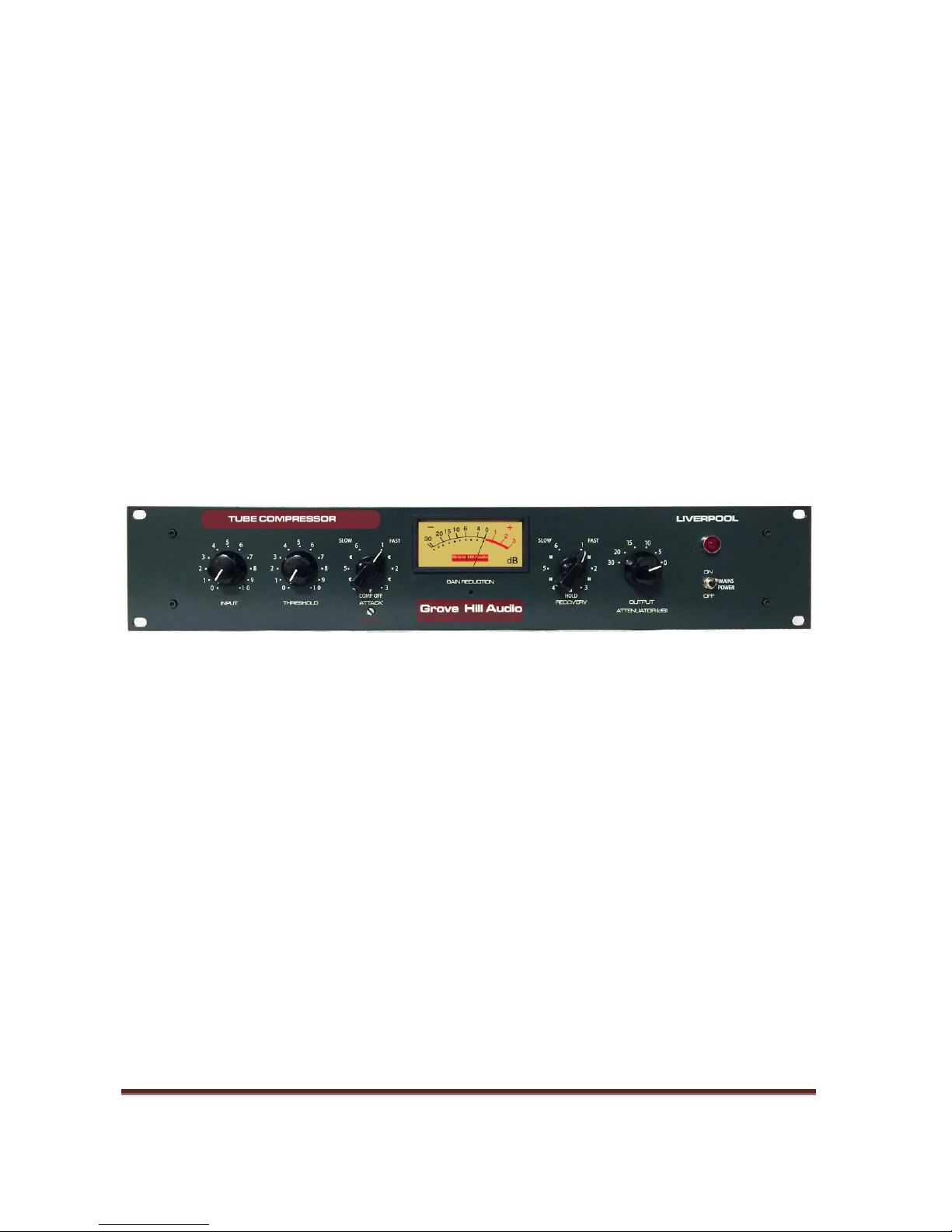
Grove Hill Audio - LIVERPOOL
OPERATING INSTRUCTIONS TUBE COMPRESSOR
Rev. 3.0

LIVERPOOL Tube Compressor Page 2
Contents
Section Page
INTRODUCTION 3
MAINS CONNECTIONS / INSTALLATION 6
FRONT PANEL / OPERATIONAL NOTES 8
TECHNICAL NOTES 14
SERVICE ADJUSTMENTS 16
SPECIFICATIONS 17
TUBE SUBSTITUTIONS 18
WARRANTY AND SERVICE 19
WARRANTY REGISTRATION 21

LIVERPOOL Tube Compressor Page 3
Introduction
THANK YOU for choosing the Grove Hill Audio Mono, Tube, Compressor.
Please take a few moments to read through this manual, there may be
features and information about this unit that are unfamiliar to you.
Thank you again, and enjoy!
Copyright and other Intellectual Property Rights
The whole content of this Manual is subject to copyrights. All copyrights
on the content of the Product Manual remain the property of Grove Hill
Audio. Any reproduction, transfer, alteration or utilization of this manual
and of the logo of Grove Hill Audio for a public and/or commercial
purpose without prior written consent of Grove Hill Audio is prohibited.
The Grove Hill Audio logo is a trademark of Grove Hill Audio, LLC.

LIVERPOOL Tube Compressor Page 4
Introduction (continued)
The LIVERPOOL is an all-tube feedback style compressor. The Mu tube
design was made famous by its use on the early rock and roll albums
recorded during the early 60’s in England. The LIVERPOOL is based upon
an American commercial sound compressor. With minor electronic
changes and the addition of key performance features, the LIVERPOOL is a
compressor that is smooth and creamy but most importantly reliable.
The Grove Hill PCB, with its excellent transformer design and component
layout, has been used to make a compressor which improved upon the
original audio circuit with added features that make LIVERPOOL usable on
many types of program sources from vocals, drums and bass to mastering.
The heart of LIVERPOOL is the dual triode remote cut-off Mu tube. This is
the gain reduction tube. This tube is re-biased by the 6AL5 vacuum tube
rectified side-chain control voltage which causes the Mu tube to smoothly
change its mutual conductance or amplification. The faithfully recreated
solid state power supply provides low noise and stability even at 30dB of
gain reduction.

LIVERPOOL Tube Compressor Page 5
GENERAL NOTES
LOCATION & VENTILATION
The Compressor unit must be installed in a stable location with ample
ventilation. It is recommended, if this unit is rack mounted, that you allow
enough clearance on the top and bottom of the unit so that there is a
constant movement of air that can flow around the ventilation unit. There
are 3 tubes inside this unit so it does run hot. Good ventilation is
encouraged to promote long life of the internal components and
consistent performance.
WATER & MOISTURE
This unit should not be used near water or moisture.
SPECIAL NOTES
Even though the tubes have metal shields around them, tubes may
become loose during transit. Straighten and press down each tube before
you plug the unit into the mains socket. Do not touch the tubes after the
unit has been switched on, as the tubes become very hot during operation
and should be handled after the power has been turned off and the tubes
are cool.
WARNING!
TO PREVENT THE RISK OF ELECTRIC SHOCK, DO NOT OPEN
THE CHASSIS.
REFER SERVICING ONLY TO QUALIFIED PERSONNEL.

LIVERPOOL Tube Compressor Page 6
MAINS CONNECTIONS
Your unit has been factory set to 115 Volts AC to comply with United
States standards. There is a selector switch to set the unit for the correct
mains voltage for your country. The voltage settings are either 115 VAC or
230 VAC at 50-60Hz. This selector switch is located on the rear panel,
above the standard IEC mains cable. The fuse is also located within the
same assembly and should be changed if the voltage is changed to 230
VAC.
INSTALLATION
1. Set the voltage change-over switch on the back of the unit to the voltage
you are using. Units are shipped set for U.S.A. standard voltage.
2. Be certain that the correct fuse is installed.
3. Connect the input signal to the 3 pin female XLR on the rear panel. The
input XLR are balanced and wired as follows:
PIN 1: GROUND
PIN 2: (+) POSITIVE GOING PHASE
PIN 3: ( - ) NEGATIVE GOING PHASE
The input impedance is 15,000 Ohms.

LIVERPOOL Tube Compressor Page 7
4. Connect a 3 pin XLR cable to the male output XLR on the rear panel. The
output XLR is balanced and the pinout is wired as follows:
PIN 1: GROUND
PIN 2: (+) POSITIVE GOING PHASE
PIN 3: ( - ) NEGATIVE GOING PHASE
The output impedance is 600 Ohms.
5. Check that the power is switched off on the unit.
6. Connect a standard IEC mains cable to the IEC mains socket on the rear
panel.
7. Connect the IEC mains cable to a 50/60 Hz AC source of the proper
selected voltage.
8. Power up the unit and allow approximately 15-30 minutes for the unit
to stabilize before using.
9. There is a LINK connector on the rear panel. This is used to connect two
units for stereo operation. Set all controls on both units exactly the same.
Connection is made by a standard, mono, Tip-Sleeve cable.
 Loading...