

Page 1
I
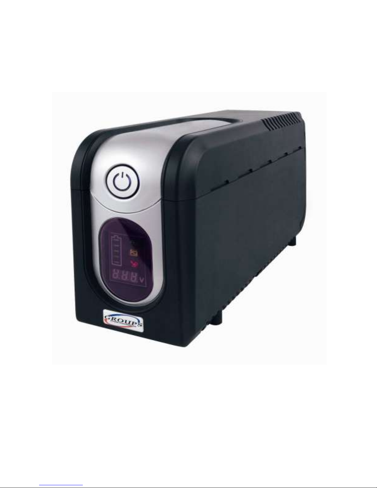
Manuale d’uso
User’s manual
Groups 700D
Page 2

II
ISTRUZIONI DI SICUREZZA
Conservare il presente manuale in un posto sicuro
ATTENZIONE: Questo manuale contiene importanti istruzioni che possono
servire per l’installazione e la manutenzione dell’UPS e delle batterie.
ATTENZIONE: Verificare che l’ambiente dove viene installato l’ UPS si a
conforme alle caratteristiche ambientali richieste
PERICOLO: Non aprire l’UPS. Questa operazione deve essere effettuata solo
da personale addestrato.
PERICOLO: Non buttare le batterie nel fuoco, possono esplodere.
PERICOLO: Non aprire le batterie perchè contengono sostanze tossiche e
nocive per la pelle e gli occhi.
PERICOLO: Le batterie sono un generatore d’energia elettrica. Fare attenzione
a non toccare e cortocircuitare i terminali di batteria. L’arco elettrico e l’energia
liberata può provocare gravi ustioni e shock da energia. Quando si opera sulle
batterie seguire le seguenti precauzioni:
rimuovere tutti gli oggetti metallici
usare utensili con impugnatura isolante
indossare guanti e stivali di gomma
Non toccare con utensili o oggetti metallici i terminali di batteria
Togliere la rete elettrica e spegnere l’UPS prima di togliere la batteria
Le operazioni di manutenzione dell’ups e delle batterie devono essere eseguite
solo da personale addestrato.
Usare solo batterie con tensione, capacità e tipo uguali .
Non collegare batterie esterne per l’aumento di autonomia all’UPS.
PERICOLO: per ridurre il rischio di incendio è installato all’interno dell’UPS un
dispositivo che limita a 20A massimi il valore di corrente, in ottemperanza al
codice elettrico nazionale, ANSI/NFPA 70.
Page 3

III
INDICE DEGLI ARGOMENTI
1. Presentazione UPS
1.1 Pannello frontale
1.2 Pannello posteriore
2. Installazione UPS
2.1 Posizionamento
2.2 Collegamento all’interfaccia del computer (optional)
2.3 Collegamento alla rete di alimentazione
2.4 Carica della batteria
2.5 Collegamento dei carichi
3. Funzioni del pulsante
3.1 Accensione con la funzione “Green Mode” abilitata
3.2 Accensione con la funzione “Green Mode” disabilitata
3.3 Spegnimento UPS
3.4 Tacitazione allarme
3.5 Test di batteria in sicurezza
4. Allarme
4.1 Allarme lento, funzionamento da batteria
4.2 Allarme rapido, batteria scarica
4.3 Allarme continuo, sovraccarico
5. Installazione software e porta interfaccia
5.1 Dati generali del software
5.2 Installazione del software
5.3 Connessione al cavo interfaccia
5.4 Caratteristiche del software UPSMON
6. Manutenzione e stoccaggio
6.1 Manutenzione
6.2 Stoccaggio a breve termine
6.3 Stoccaggio a lungo termine
7. sostituzione delle batterie
7.1 Istruzioni di sicurezza
7.2 Procedura sostituzione batteria
Appendice A Soluzione di piccoli problemi
Appendice B Specifiche tecniche
Page 4
4
1. Presentazione
L’UPS è di tipo line interactive. In presenza di rete l’UPS protegge ed alimenta il
carico, caricando anche le batterie interne. Al mancare della rete elettrica l’UPS con
l’ausilio delle batterie provvede ad alimentare il carico.
1. Controllo a microprocessore per rendere le performance dell’UPS migliori
possibili.
2. Adeguamento della frequenza a quella delle rete elettrica.
3. Carica batterie controllato dal microprocessore per garantire la carica
corretta delle batterie.
4. Protezione al sovraccarico in funzionamento da rete e da batteria.
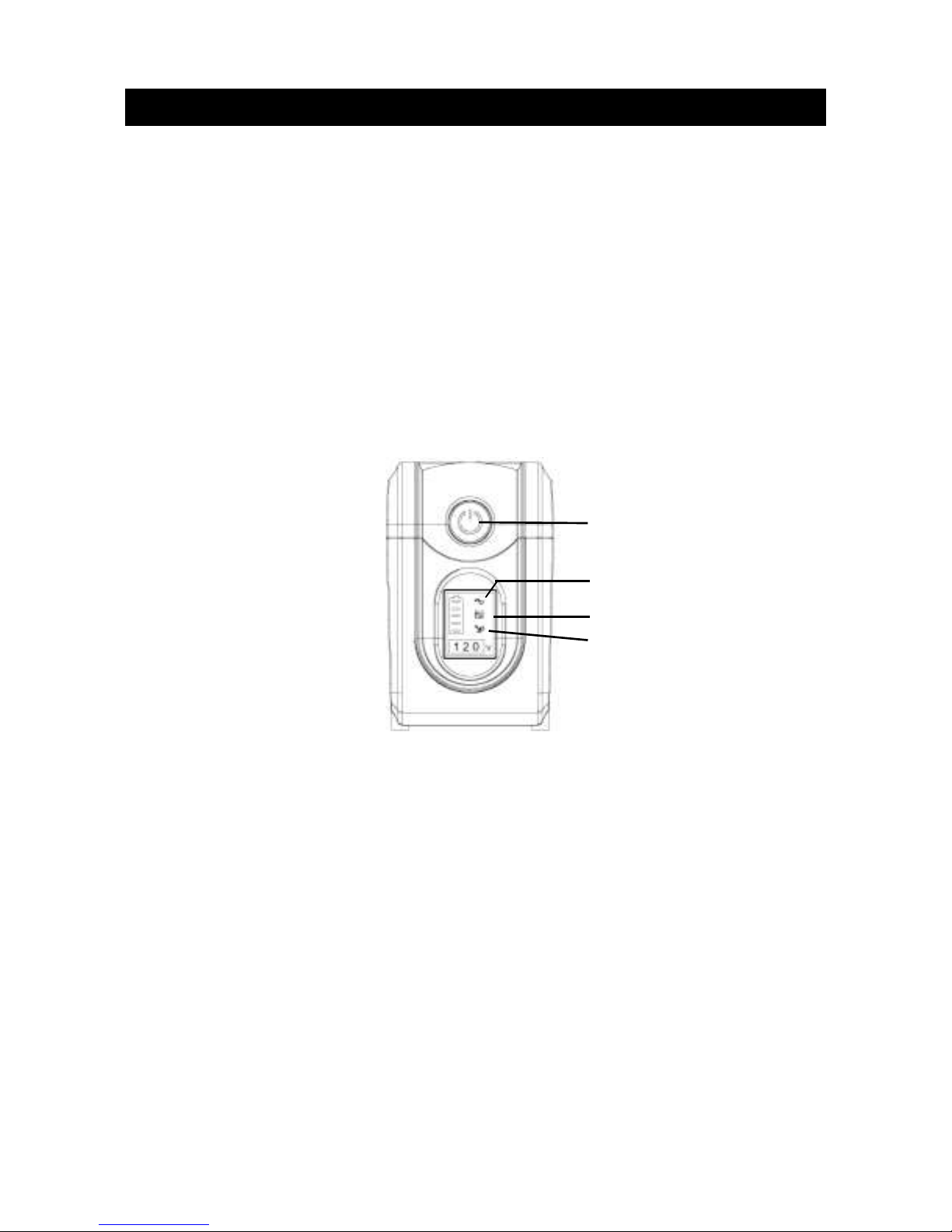
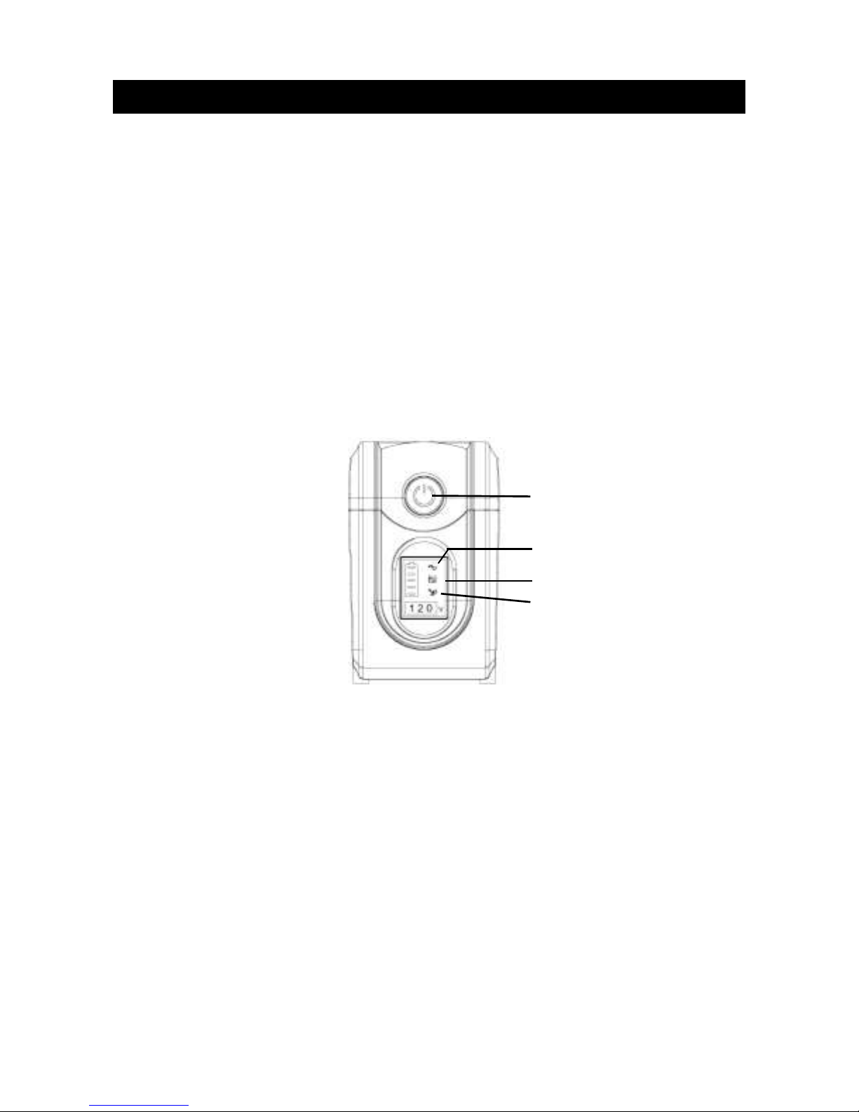
Pannello frontale
TASTO di: “ ON/OFF - BATTERY TEST – TACITAZIONE ”
L’UPS può essere acceso sia con la rete elettrica che da batterie. Premendo il
pulsante fino ad udire un bip si accendere o spegne l’UPS. E’ possibile eseguire il
battery test, con la rete elettrica presente, tenendo premuto il pulsante meno di 1
secondo; questa procedura verifica l’efficienza delle batterie. In funzionamento da
batteria, per tacitare l’UPS, premere il pulsante per almeno 1 sec.
“Funzionamento da rete” (led verde)
Il led è acceso se la rete di ingresso è in condizioni normali
“Funzionamento da batteria” (led giallo)
Il led è acceso quando l’UPS funziona da batteria
“Allarme batterie esauste o sovraccarico” (led rosso)
Questa segnalazione può indicare due anomalie:
1. Se resta illuminato con luce fissa, significa che bisogna sostituire le batterie
o che il caricabatterie non funziona.
2. Se si illumina ad intermittenza, l’UPS è in sovraccarico, vale a dire che la
potenza che si preleva è maggiore di quella che l’UPS può fornire.
Page 5
5
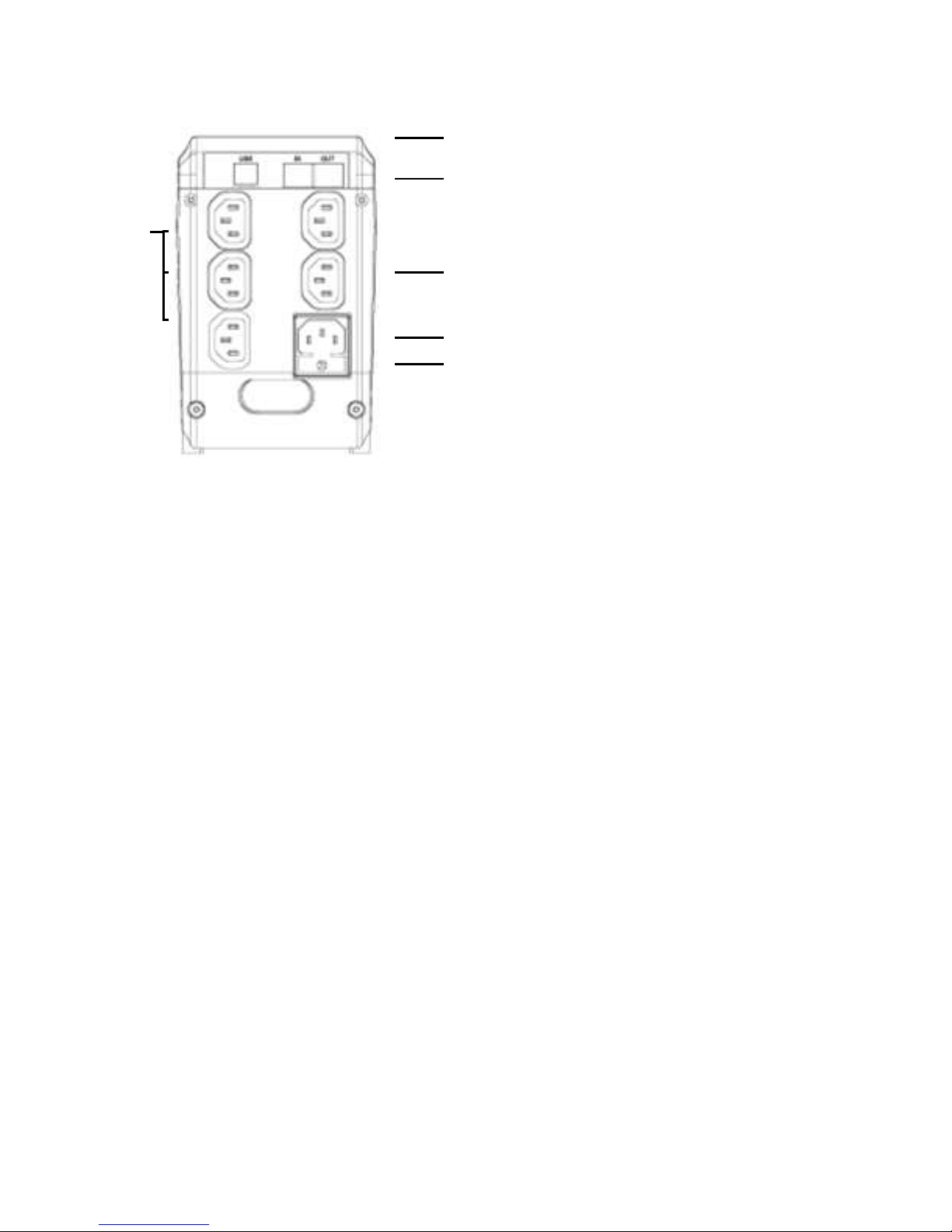
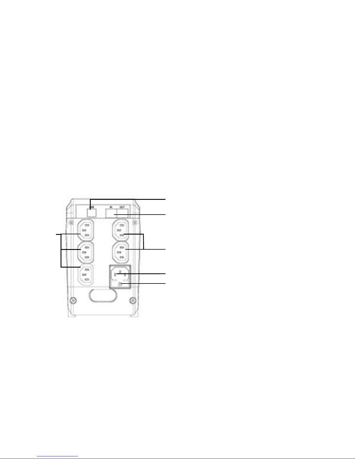
Pannello posteriore
INTERFACCIA USB
E’ possibile collegare l’UPS al computer usando il cavo in dotazione tramite la porta
USB presente sul retro. Il software di gestione può supportare i seguenti sistemi
operativi: NOVELL, LINUX, UNIX, WINDOWS.
PROTEZIONE MODEM
E’ un filtro che permette di proteggere la linea telefonica da piccole sovratensioni.
PRESA di ALIMENTAZIONE
La presa di tipo IEC viene alimentata attraverso il cavo in dotazione. Verificare che la
rete di alimentazione sia 230Vac 50/60Hz.
FUSIBILE di ALIMENTAZIONE
La presa è dotata di fusibile per la protezione dell’UPS e dei carichi collegati.
USCITE PROTETTE
Queste prese permettono di alimentare le utenze in continuità. Se il valore della
tensione di alimentazione dell’UPS supera i limiti funzionali, si inserisce l’A.V.R. che
stabilizza la tensione al carico. Se la tensione di alimentazione manca o è fuori
tolleranza l’UPS si stacca dalla rete elettrica e funziona da batteria.
USCITE FILTRATE
Queste prese permettono di alimentare le utenze che possono rimanere senza
alimentazione. Le prese, collegate tramite un filtro alla presa di alimentazione,
consentono l’alimentazione di stampanti, e tutti gli apparecchi non critici. Il filtro
inserito protegge da sovratensioni di modesto valore tutte le utenze collegate.
Page 6
6
2. Installazione
Verificare che l’imballo e l’UPS siano integri. L’imballo è riciclabile è può essere
riutilizzato.
2.1 Posizionamento:
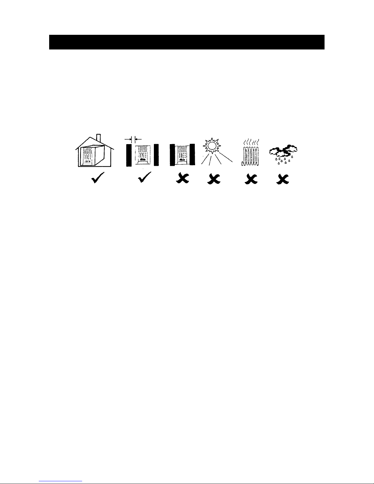
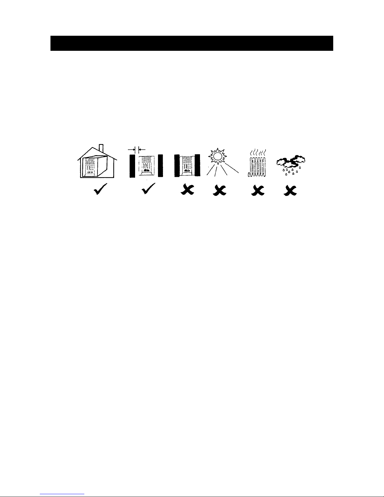
Installare l’UPS in un luogo asciutto, con adeguata ventilazione, e con poca polvere.
Non installare l’UPS in zone dove temperatura e umidità hanno valori fuori dai limiti
indicati nelle specifiche tecniche
2.2 Connessione interfaccia software:
Non è necessario utilizzare la porta USB e il software in dotazione per verificare il
funzionamento corretto dell’UPS. Il software UPSMON installato su un computer
consente di monitorare l’UPS, esegue lo shut-down del computer e dell’UPS stesso.
Consente inoltre di accendere e spegnere l’UPS in modo programmato, di aver uno
storico di funzionamento, etc..
Attenzione: collegare l’UPS al computer utilizzando il cavo USB in dotazione
2.3 Collegamento alla rete elettrica:
Usare il cavo di alimentazione in dotazione per alimentare l’UPS dalla rete elettrica,
verificando che il valore della stessa sia corretto (230 Vac 50/60Hz).
2.4 Carica della batteria:
L’UPS carica la batteria anche quando è spento se è collegato dalla rete elettrica. Si
consiglia di caricare la batteria per 24 ore, prima di utilizzare l’UPS.
2.5 Collegamento dei carichi:
Connettere I cavi di alimentazione delle vostre apparecchiature alle prese di uscita
presenti nel pannello posteriore .
ATTENZIONE:
non collegare stampanti laser o plotter alle prese protette (5- pag. 6)
perché la potenza richiesta da queste apparecchiature è maggiore del
valore nominale erogabile dall’UPS.
2.5cm (per parte)
Page 7

7
3. Funzioni del pulsante
3.1 Tasto di accensione (1- pag. 5 ) e funzionamento “green mode”
Dopo aver collegato l’UPS all’alimentazione elettrica di rete premere il tasto “on-off”
fino a che il beep non si tacita. A questo punto l’UPS è acceso. Successivamente
collegare le apparecchiature da alimentare alle prese nella parte posteriore
dell’UPS. Nel funzionamento da batteria, se il carico collegato è minore del 10%
della potenza nominale dell’UPS, questo si spegnerà dopo 4 minuti. Questa
funzione “green mode” consente di preservare l’energia delle batterie.
ATTENZIONE: se l’UPS si è spento con la funzione di “green mode” al ritorno
della rete elettrica si riaccenderà automaticamente.
ATTENZIONE : Non alimentare stampanti laser o plotter in quanto assorbono
picchi di energia non sostenibili dall’UPS.
3.2 Disattivare la funzione “green mode”
L’operazione deve essere eseguita in presenza di rete elettrica. Premendo il
pulsante di “ON” per alcuni secondi fino alla tacitazione del segnale acustico, è
possibile disattivare la funzione “green mode”. Quindi, anche in presenza di carico
nullo o inferiore al 10% della potenza nominale, l’ UPS rimarrà acceso. In tale caso
l’UPS scaricherà completamente tutta l’energia delle batterie.
3.3 Spegnimento
Premere il pulsante “OFF” per più di 3 sec. L’UPS si spegne sia in funzionamento da
rete che da batteria.
ATTENZIONE: L’UPS può caricare le batterie anche in posizione di “OFF”.
(Advanced Battery Management Technology)
3.4 Tacitazione dell’allarme :
In funzionamento da batteria l’UPS continua ad emettere un segnale di allarme. E’
possibile tacitare l’allarme premendo per 1 sec il pulsante “SILENCE” (1 pag. 5). La
tacitazione si disattiva automaticamente per successive condizioni critiche quali:
“batteria scarica” o“sovraccarico”
3.5 Test di funzionamento
Premendo il pulsante “TEST” con la rete elettrica presente per 0.5 sec. è possibile
eseguire il test automatico in sicurezza delle batterie.
Page 8

8
4. Allarmi
4.1 “Funzionamento da batteria” (allarme lento)
Quando l’UPS è in funzionamento da batteria emette un allarme acustico ripetitivo
con frequenza lenta. L’allarme si tacita quando l’UPS ritorna in funzionamento da
rete.
ATTENZIONE: L’allarme di funzionamento da batteria ha una frequenza di 2
secondi tra due beep .
ATTENZIONE: L’UPS può essere tacitato premendo il tasto “ON”. Sarà
sufficiente tornare a premere il tasto “ON” per riattivare il segnale
acustico.
4.2 “Batteria in fine scarica”
Se l’UPS in funzionamento da batteria, raggiunge un livello di carica delle batterie
vicino al al 20-30 %, l’allarme aumenterà la frequenza di emissione del suono.
ATTENZIONE L’allarme di funzionamento da batteria ha una frequenza di 0.5
secondi tra un beep e l’altro.
ATTENZIONE: in condizione di batteria scarica l’UPS non può essere tacitato.
4.3 “Sovraccarico”
Se all’UPS viene collegato un carico di potenza superiore al nominale, si attiva la
funzione di “OVERLOAD”. In questo caso il suono emesso dall’UPS è continuo e se
la condizione persiste la macchina si spegnerà dopo alcuni secondi.
5. Software e porta di interfacciamento
5.1 Software di monitoraggio
Il software UPSMON consente di monitorare le molteplici funzioni dell’UPS e
provvede anche ad effettuare lo shut-down del computer nel caso di mancanza della
rete elettrica. Inoltre è possibile ottenere un grafico relativo all’andamento nel tempo
dei seguenti parametri: tensione, frequenza, stato di batteria. Il software è disponibile
per : Windows 98, Windows Me, Windows 2000, Windows XP, Windows NT 4.0 or
later, Novell Netware, Linux, e altri sistemi operativi a richiesta.
5.2 Installazione del software
Per installare il software UPSMON seguire le seguenti operazioni:
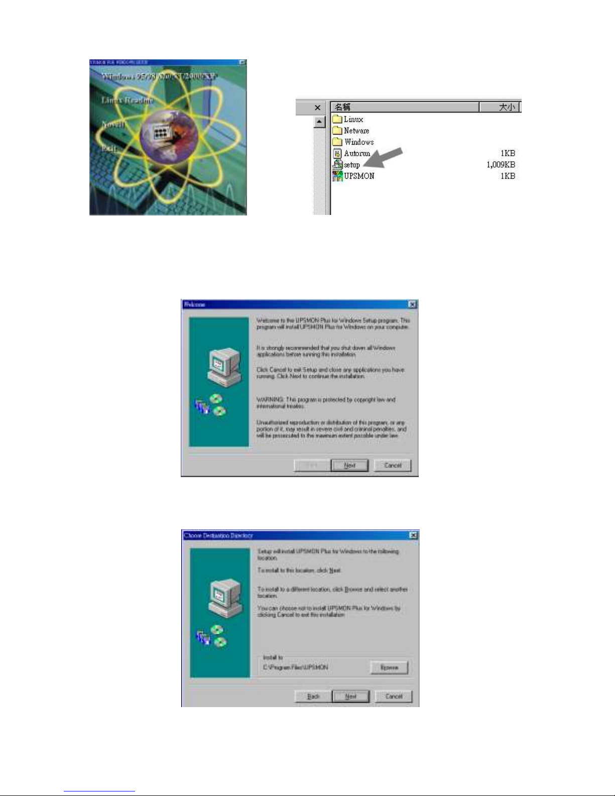
1. Inserire il CD Rom UPSMON nel lettore di CD-ROM del computer. L’installazione
parte automaticamente e appare il menu come il Fig 5.1. Selezionare poi il
sistema operativo del computer dove si desidera installare il software UPSMON.
Note : Se l’installazione non parte automaticamente selezionare
startProgramsWindows Explorer( per Windows 98)e fare un doppio click su
setup icona( fig. 5.2).
Page 9
9
Fig 5.1
Fig 5.2
2. Appare il benvenuto di windows” Welcome…..” quindi seguire le istruzioni
riportate. Fare click su “Next”. ( Fig 5.3)
Fig 5.3
3. Selezionare il percorso dove installare il programma, seguendo le istruzioni
riportate. Fare click su Next. ( Fig 5.4)
Fig 5.4
Page 10
10
4. Leggere e seguire le istruzioni che seguono per completare l’installazione.
5.3 Collegamento del cavo di interfaccia
Collegare il cavo d’interfaccia (usare esclusivamente quello in dotazione all’UPS)
dalla porta USB (1- pag. 5) dell’UPS a una porta USB disponibile del computer.
5.4 Caratteristiche del software UPSMON
Le più importanti funzioni del software UPSMON sono:
Messaggio a video di mancanza rete elettrica
Chiusura dei file aperti (MS OFFICE) prima che le batterie siano esaurite.
Corretta chiusura del sistema operativo.
Spegnimento dell’UPS per preservare l’energia delle batterie.
5.5 Come usare il software UPSMON
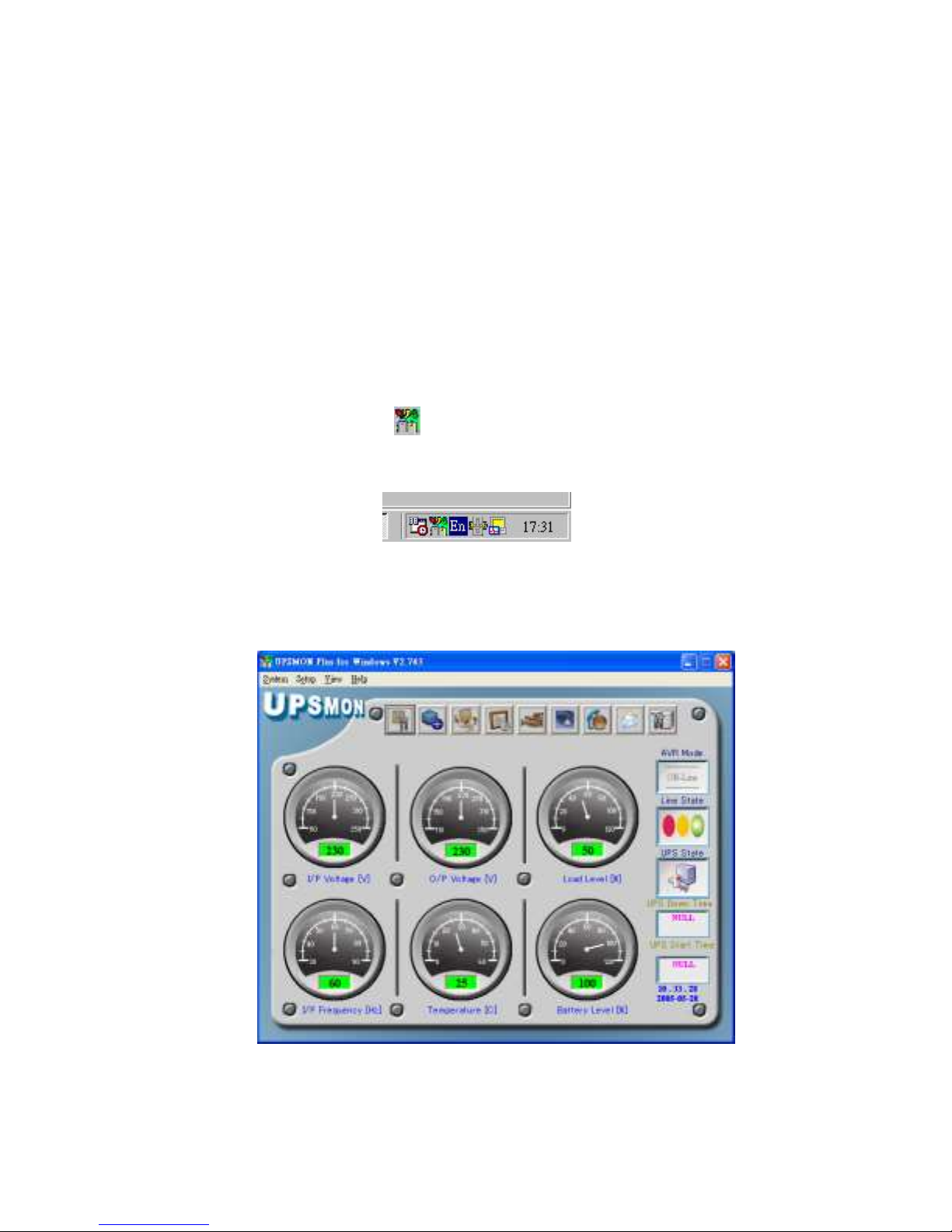
Dopo aver completato l’installazione del software UPSMON, si può avviare il
programma ciccando sull’icona presente nella barra strumenti del computer ( fig.
5.5)
Fig 5.5
il menu principale appare come in Fig 5.6
Fig 5.6
Nel menu ci sono molti strumenti per gestire e controllare l’UPS. Per vedere i dati o
attivare le varie funzioni fare un click all’aiuto HELP.
Page 11

11
6. Manutenzione e stoccaggio
6.1 Manutenzione
6.1.1. pulire ogni 6 mesi, a seconda del luogo di installazione, le griglie di
aerazione.
6.1.2. pulire le superfici dell’UPS con un panno morbido.
6.1.3. controllare che i cavi siano ben collegati all’UPS.
6.1.4. posizionare l’UPS su di una superficie stabile .
6.1.5. lasciare uno spazio di almeno 10 cm tra il pannello posteriore dell’UPS e
l’ostacolo contiguo. Questo permetterà un’adeguata ventilazione.
6.1.6. non lasciare l’UPS esposto ai raggi solari diretti o in luogo molto umido.
6.1.7. tenere lontano da fonti di calore
6.1.8. non appoggiare altri prodotti sopra l’UPS.
6.1.9. non installare l’UPS in ambienti dove l’aria contiene agenti corrosivi.
6.1.10 la temperatura dell’ambiente di installazione non deve essere al di fuori del
range definito.
6.2 Stoccaggio a breve termine (3 mesi)
Caricare per almeno 8 ore le batterie dell’UPS prima stoccarlo. Scollegare tutti
gli accessori, pulire l’UPS e riporlo nell’imballo originale.
6.3 Stoccaggio a lungo termine (oltre 3 mesi)
Eseguire le operazioni al punto 6.2.
Ricaricare le batterie dell’UPS, collegandolo alla rete elettrica, ogni:
6 mesi se la temperatura di conservazione è compresa tra -15 e +
30°C
3 mesi se la temperatura di conservazione è compresa tra +30 e +
45°C
7. Sostituzione della batteria
La batteria entro contenuta ha una vita media di tre anni. Se l’autonomia dell’UPS
tende a diminuire, ricaricare 24 ore la batteria e verificare se tutto è nella normalità.
Qualora il tempo non aumenti è consigliata la sostituzione della batteria. Prima di
procedere alla sostituzione descritta al punto 7.2 leggere attentamente il punto
7.1.
7.1 ISTRUZIONI DI SICUREZZA
La batteria dovrebbe essere sostituita da un centro di assistenza abilitato. Nel caso
si scelga una soluzione diversa comunque l’operazione di sostituzione deve essere
effettuata esclusivamente da personale addestrato, seguendo attentamente le
istruzioni riportate.
Page 12

12
ATTENZIONE: La batteria è una riserva di energia pericolosa se i poli ( +/- ) vengono
messi in corto circuito, quindi osservare le seguenti precauzioni:
1. Togliere gli oggetti metallici quali, orologio, anelli o altro.
2. Usare attrezzi con impugnatura isolata.
ATTENZIONE: Non buttare le batterie nel fuoco, possono esplodere.
ATTENZIONE: Non aprire le batterie perchè contengono sostanze tossiche e nocive
per la pelle e gli occhi.
ATTENZIONE : Quando si sostituisce la batteria controllare che sia dello stesso tipo
e con le stesse caratteristiche tecniche ( tensione V, capacita Ah e tipo).
7.2 Procedura di sostituzione della batteria
La sostituzione della batteria dovrebbe essere fatta solo da un centro di assistenza
qualificato. Per sostituire la batteria è necessario smontare completamente l’ups,
quindi l’operazione è particolarmente pericolosa perché vi sono parti in tensione
anche senza rete elettrica, con ups spento, e batteria scollegata. Pertanto la persona
che si appresta alla sostituzione di batteria deve essere un tecnico qualificato e
addestrato.
Appendice A ricerca guasti
PROBLEMA
POSSIBILE CAUSA
SOLUZIONE
UPS non si
accende
Led non si
accendono e non
si sente nessun
suono (beep)
Pulsante di ON premuto
troppo poco
Premere il pulsante per più di 2
secondi
Le uscite dell’UPS possono
essere in corto circuito o il
carico è troppo elevato
( overload)
Spegnere l’UPS e verificare il
carico. Premere per piu’ di 2
secondi il pulsante ON
Il led di “BACKUP
mode” è acceso
anche se le rete
elettrica è presente.
La tensione della rete
elettrica è fuori tolleranza
Nessuna soluzione
Verificare la presenza della
rete elettrica
Verificare le connessioni alle
rete elettrica
Fusibile danneggiato o
interruttore guasto
Sostituire il fusibile o resettare
l’interruttore.
Page 13

13
Il led di batteria è
acceso e l’allarme
suona in
continuazione
L’ UPS è in sovraccarico
Diminuire il numero delle
apparecchiature alimentate
L’autonomia delle
batterie è diminuita
La batteria non è
completamente carica
Ricaricare le batterie per 24
ore consecutive
L’ UPS è in sovraccarico
Rimuovere il carico eccedente
Le batterie sono esauste per
l’avvicinarsi del limite di vita
Sostituire la batteria
Il carica batterie non
funziona bene
Contattare l’assistenza per una
verifica
L’autonomia è 4 min.
con carico vicino a 0
E’ attiva la funzione “green
mode”
Se il carico è inferiore a 30W
disattivare la funzione “Green
Mode” (veder 3.2)
Page 14

I
Appendice B dati tecnici
Modello
GROUPS 700 D
Ingresso
Potenza
700 VA - 400 W
Tensione
230Vac
Frequenza
50 o 60Hz +/-10% (auto sensing)
Uscita
Tensione
230 Vac +/-5%
Frequenza
50 o 60Hz +/-1%
Tempo di intervento
4 msec
Protezioni e
filtri
Protezione agli
spike
420Joules(2x0V) / 225Joules(1x0V) , 8/20us
Protezione da rete
Fusibile e interruttore
Protezione modem
RJ11 telefonica ed RJ45 LAN
Protezione
sovraccarico
L’UPS si spegne automaticamente( in 60 sec) se il
carico eccede al 110% del nominale e in 3 sec. se
eccede al 130%.
Corto circuito in
uscita
L’UPS si spegne immediatamente o si aprono le
protezioni verso la rete elettrica
Batterie
Tipo
Ermetiche al piombo
Tempo di ricarica
6 ore (al 90% della capacità)
Protezione
Automatica per eccessiva scarica
Autonomia
a seconda della potenza assorbita
Caratteristic
he fisiche
Peso
Kg
6.3
Dimensioni (l x p x
h) mm
105 x 334 x 168
Allarmi
Funzionamento da
batteria
Lento beep ( 0.47Hz)
Batteria quasi
scarica
Beep rapido ( 1.824Hz)
Sovraccarico
Beep continuo
Interfaccia
Digitale
Porta USB con software di gestione UPSMON
Condizioni
ambientali
Ambiente
3500m max, Umidità: 0%-95%( senza condensa),
Temperatura:
0-30℃
Rumorosità
<40dBA (ad 1 metro)
Stoccaggio
15000 metri max.
Page 15

II
Important Safety Instructions
IMPORTANT SAFETY
INSTRUCTIONS
SAVE THESE INSTRUCTIONS
WARNING (SAVE THESE INSTRUCTIONS): This manual
contains important instructions that should be followed during installation and
maintenance of the UPS and batteries.
WARNING (CONTROLLED ENVIRONMENT): These units are
intended for installation in a temperature controlled, indoor area free of conductive
environment.
CAUTION: Risk of electric shock, do not remove cover. No user serviceable parts
inside. Refer servicing to qualified service personnel.
CAUTION: Do not dispose of batteries in a fire, the battery may explode.
CAUTION: Do not open or mutilate the battery, released electrolyte is harmful to
the skin and eyes. It may be toxic.
CAUTION: A battery can present a risk of electric shock and high short circuit
current. The following precaution should be observed when working on batteries
Remove watches, rings or other metal objects.
Use tools with insulated handles.
Wear rubber gloves and boots.
Do not lay tools or metal parts on top of batteries.
Disconnect charging source prior to connecting or disconnecting battery terminals.
Servicing of batteries should be performed or supervised by personnel knowledgeable
of batteries and the required precautions. Keep unauthorized personnel away from
batteries.
When replacing battery, replace with same type.
Do not connect any additional batteries by yourself.
Symbol for On/Off is displayed and defined.
CAUTION: To reduce the risk of fire, connect only to a circuit provided with 20
amperes maximum branch circuit overcurrent protection in accordance with the
National Electrical Code, ANSI/NFPA 70.
Page 16

III
Table of contents
Important Safety Instructions ..............................................................................II
Table of contents .................................................................................................. III
Introduction ........................................................................................................... V
Please read and save this manual .................................................................................. V
Please save or recycle the packaging materials ............................................................. V
Intelligent microprocessor control ................................................................................ V
Advanced battery management ..................................................................................... V
Advanced monitoring software ..................................................................................... V
1. Presentation ........................................................................................................ 4
Front Panel..................................................................................................................... 4
Rear Panel ...................................................................................................................... 7
2. Installation .......................................................................................................... 6
2.1 Placement: ............................................................................................................... 6
2.2 Connect Computer Interface (optional): .................................................................. 6
2.3 Connect to Utility: ................................................................................................... 6
2.4 Charge the battery: ................................................................................................... 6
2.5 Connect the loads:.................................................................................................... 6
3. Operation ............................................................................................................ 7
3.1 Switch on with “Green Mode” Function .................................................................. 7
3.2 Switch on with “Disabled Green Mode” Function ................................................... 7
3.3 Switch off ................................................................................................................ 7
3.4 Silence: .................................................................................................................... 7
3.5 Self-test function ...................................................................................................... 7
4. Alarm ................................................................................................................... 8
4.1 “BACKUP” (slow alarm) ........................................................................................ 8
4.2 “LOW BATTERY” (rapid alarm) ............................................................................ 8
Page 17

IV
4.3 “OVER LOAD” (continuous alarm) ........................................................................ 8
5. Software installation and Interface Port .......................................................... 8
5.1 Power Monitoring Software ..................................................................................... 8
5.2 Installing software ................................................................................................... 8
5.3 Connecting interface cable ..................................................................................... 10
5.4 The characteristics of software UPSMON ............................................................. 10
6. Maintenance and storage ................................................................................. 11
6.1 Maintenance............................................................................................................11
6.2 Storage conditions ................................................................................................. 15
6.3 To extend the storage ............................................................................................. 15
Appendix A Troubleshooting ...........................Errore. Il segnalibro non è definito.
Appendix B Specifications ..................................................................................... I
Page 18

V
Introduction
SAVE THESE INSTRUCTIONS
Please read and save this manual
Thank you for selecting this uninterruptible power system (UPS). It provides you with a
perfect protection for connected equipment. The manual is a guide to install and use the UPS.
It includes important safety instructions for operation and correct installation of the UPS. If
you should have any problems with the UPS, please refer to this manual before calling
customer service.
Please save or recycle the packaging materials
The UPS‘s shipping materials are designed with great care to provide protection within
delivery. These materials are invaluable if you ever have to return the UPS for service.
Damage happened during transit is not covered under the warranty.
Intelligent microprocessor control
The product is an advanced line-interactive UPS based on microprocessor control. This
means that it operates with the newest technology, high performance and powerful function.
The line-interactive UPS is an intelligent protector and provides pure, reliable AC power to
the critical loads - protecting them from utility power blackout, swells, sags, surges and
interference. The loads could include sensitively medical instruments, computers,
telecommunication systems, and industrially automatic equipment. Under power normal
condition, the line-interactive design enables the system to adjust and filter power
fluctuations continuously and automatically. In the event of power failure, it can provide
immediately back-up power from the batteries without any interruption. Complete
transference will be achieved within 4m seconds, with no interruption.
Beside this, when the utility power is connected, the charger would work automatically even
under power switch is OFF. Furthermore, in order to save the battery energy, UPS can be set
to turn it off under backup mode if none of the connected loads is operating.
Advanced battery management
The visual and audible indications of the UPS present the battery’s status including capacity
degree and battery condition. Self-test function let UPS detect a weak battery before it is put
into service. The UPS normally perform a self-test at power up and manual self-test
condition. Self-test function can be conducted manually with the ON/TEST switch at any
time.
Advanced monitoring software
The line-interactive UPS and UPSMON series monitoring software (optional kits) make
your computer operate intelligent and provide you with the ability of perfect protection of
your critical devices. The software is available for most operation systems and is supplied
with a communication cable that connects to the UPS.
Page 19
6
1. Presentation
The UPS is a line interactive uninterruptible power system (UPS). When utility
input is normal, the UPS would provide surge protection and energy to charge
the internal battery. If the utility input is abnormal, the UPS can supply AC
power to the loads immediately.
(1). Utilizes microprocessor based controls, it will minimizes the dependency on hardware.
Beside this, it maximizes system flexibility and optimizes the assurance of reliability.
(2). Automatic frequency selection to match with utility power.
(3). High-grade battery charger to prolong battery’s life and fully charge the battery.
(4). With actual overload protection both in line and battery mode.
Front Panel
LCD type
“ON/OFF/TEST/SILENCE” button
No matter the UPS plugged in or not. Press the “ON/OFF/TEST/SILENCE” button till the
beep stop to turn on or to turn off the UPS. When UPS is working under AC mode, it also
activates the UPS‘s self-test by press the bottom less than 1 second.
In back up mode, press the bottom about 1 second to activate the UPS’s silence function.
“LINE mode” indicator (Green)
The indicator will illuminate when the utility input is normal.
“BACKUP mode” indicator (Yellow)
The indicator illuminates when the power is supplied from the battery.
Page 20
7
“OVER LOAD” indicator (Red)
The indicator illuminates when the connected loads exceed the maximum rated capacity.
“Battery Fault indicator (Red)
The indicator illuminates two statuses of the UPS: When this Red LED is steady illuminated,
it indicates that the battery needs to be replaced or the charger of UPS is fail to function.
When this Red LED flashes rapidly, it indicates the UPS is over loaded.
“Battery level” bar
It indicates the battery capacity and battery status. When the battery capacity is low, it
becomes dim, when the battery needs to be replaced or the charger of UPS is fail to function,
indicators on all the bar flash.
“Output Voltage”
This digital indicates present output voltage.
Rear Panel
Page 21

8
REMOTE PORT
Provide USB to support NOVELL, LINIX, UNIX, WINDOWS and other operating systems.
TEL/ MODEM protection
Telecom transfer ports provide users to extend the applications.
Caution: To reduce the risk of fire, use only No. 26AWG or larger telecommunication line
cord.
AC INPUT POWER RECEPTACLE
The input power cord needs to connect the rear inlet socket of the UPS and plug into a
socket on the wall. Please notice the voltage of utility power should match with the UPS. For
example, the rating voltage of UPS is 110V/(220V), the input utility power should be the
same as 110V/(220V).
INPUT CIRCUIT BREAKER/ FUSE
It trips when the connected loads exceed the protected receptacle‘s capacity.
UPS & SURGE PROTECTED OUTLETS
When utility power is normal, the UPS outlets are powered by utility power with AVR
function. Any higher or lower utility power would be rectified by AVR function. When
utility power is fail, the UPS outlets are powered from battery.
CONVENIENCE OUTLET(S)
CONVENIENCE outlets protect the loads from spike.
Coaxial surge suppression port (option)
Page 22
9
2. Installation
Inspect the UPS upon receipt. The packaging is recyclable; keep it for reuse or be disposed of
properly.
2.1 Placement:
: Install the UPS in a protected area with adequate flowing air and free of excessive dust. Do
not operate the UPS where the temperature and humidity is out of the specified limits.
2.2 Connect Computer Interface (optional):
UPSMON series software (or other power management software) and an interface kits can be
used with this UPS. Use only kits supplied or approved by the manufacturer. If used, connect
the computer interface port and the REMOTE port of the UPS using the bonding cable.
Note: Computer interface connection is optional. The UPS works properly without a
computer interface connection.
CAUTION: Use only factory supplied or authorized UPS monitoring cable!
2.3 Connect to Utility:
The input power cord needs to connect the rear inlet socket of the UPS and plug into a
socket on the wall. Please notice the voltage of utility power should match with the UPS. For
example, the rating voltage of UPS is 110V/(220V), the input utility power should be the
same as 110V/(220V).
2.4 Charge the battery:
The UPS charges its battery whenever it is connected to utility power. For best results,
charge the battery for 24 hours in the initial use.
2.5 Connect the loads:
The employed equipment’s power cords (such as computer) are plugged into the sockets on
the rear panel.
CAUTION: Never connect a laser printer or plotter to the “ UPS outlets”. A laser printer
or plotter periodically draws significantly more power than when its idle status,
and may overload the UPS.
2.5cm (1 inch)
Page 23

10
3. Operation
3.1 Switch on with “Green Mode” Function
When utility input is connected to the UPS, press “ON” button and keep pressing until the
“Bi” beep stops to turn on the UPS. After that, connect the electrical cords of the
equipments that will be used (such as desktop computer and CRT monitor) to the rear panel
of UPS. In order to save the power, it will also automatically enable the “Green mode” - No
Load (or Light load) shut-down function under backup mode (about 4 minutes later).
ATTENTION: At backup mode, UPS can be automatically shut-down if none of the
connected loads is operating. (Green mode; No Load shut down function)
Once the utility power is normal again, the unit can be waked up by itself.
CAUTION: Never connect a laser printer or plotter to the UPS. A laser printer or plotter
periodically draws significantly more power than its idle status, and may
overload the UPS.
3.2 Switch on with “Disabled Green Mode” Function
When utility input is connected to the UPS, press “ON” button and keep pressing until
the ”Bi.Bi-Bi” beeps stopped to turn on the UPS. After that, connect the electrical cords of
the equipments that will be used (such as Notebook computer and LCD monitor) to the rear
panel of UPS. If the load is lighter than 30W, please also refer this function to avoid any
inconvenience cause by “Green Mode” function.
3.3 Switch off
Press the “OFF” button at “LINE” or “BACKUP” modes and keep pressing more than 3
second to turn off the UPS.
ATTENTION: UPS can automatically charge itself under ”OFF” mode. (Advanced Battery
Management Technology)
3.4 Silence:
When UPS is under “BACKUP” mode, press the “SILENCE” button about 1 second to
silence the audible alarm. The function is disabled when UPS is under condition of “LOW
BATTERY” or “OVERLOAD”
3.5 Self-test function
Press the “TEST” button at “LINE” mode about 0.5 second, UPS will perform self-test
procedure automatically.
ATTENTION: No load shut-down function can be disabled by pressing button until bi-bi
beep to turn on the UPS.
Page 24

11
4. Alarm
4.1 “BACKUP” (slow alarm)
When the UPS is working under “BACKUP” mode, the UPS would emit audible alarm. The
alarm stops when the UPS is return to “LINE” mode operation.
ATTENTION: The alarm of “BACKUP” is going to beep every 2 seconds. ( Slow-speed
beep).
ATTENTION: The UPS provides mute function for the warning. When the beeping sound
occurs, press "ON" to stop it; and press "ON" again to resume the sound.
4.2 “LOW BATTERY” (rapid alarm)
In the “BACKUP” mode, when the energy of battery becomes to lower level. ( about 20% ~
30%) The UPS beeps rapidly until the UPS shuts down from battery exhaustion or returns
to “LINE” mode operation.
ATTENTION: The alarm of the batteries caused by low voltage beeps every 0.5 second.
ATTENTION: The rapid alarm under “LOW BATTERY” condition cannot be muted.
4.3 “OVER LOAD” (continuous alarm)
When the UPS is working under overload condition (the connected loads exceed the
maximum rated capacity), the UPS will emit continuous alarm to warn an overload
condition. In order to protect the unit and the loads, the UPS will be automatic turn off.
Please disconnect nonessential devices from UPS to eliminate the overload alarm.
Page 25
12
5. Software installation and Interface Port
5.1 Power Monitoring Software
The UPSMON series software (or other power monitoring software) is applied standard
interface to perform monitoring functions, and then provides an orderly shutdown of a
computer in the event of power failure. Moreover, UPSMON displays all the diagnostic
symptoms on monitor, such as Voltage, Frequency, Battery level and so on. The software is
available for Windows 98, Windows Me, Windows 2000, Windows XP, Windows NT 4.0 or
later, Novell Netware, Linux, and others. Call your dealer for more information on computer
OS compatible solutions.
5.2 Installing software
To perform monitoring functions, you must install UPSMON series software accompanied
with the UPS. Please do the following steps to complete installation of UPSMON series
software.
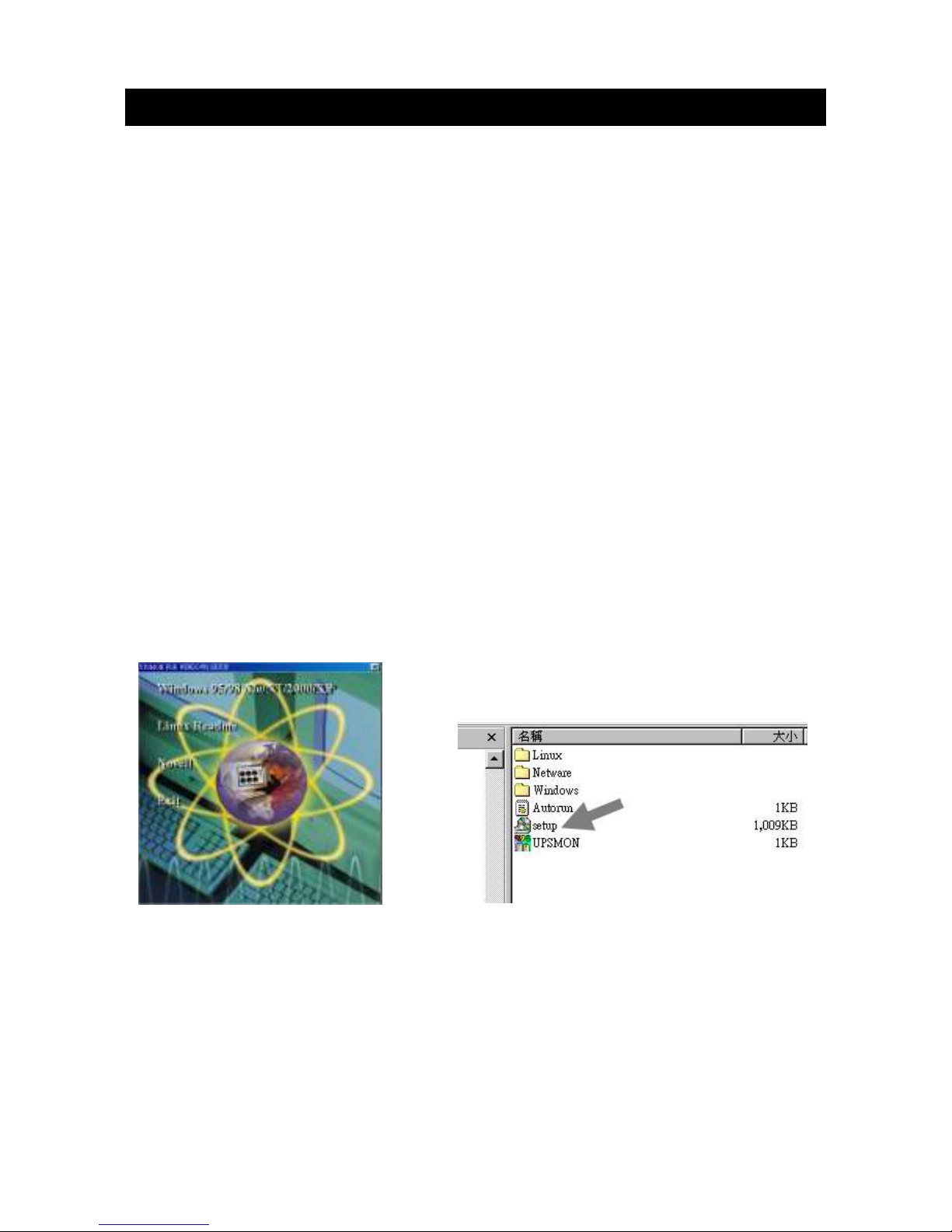
5. Insert the UPSMON CD into your CD-ROM drive. The installation program should start
automatically and installation menu appear as shown in Fig 5.1. Please select the
operating system applied for your computer and then click on it. (For example if your
operating system is Windows 98, please click select item Windows 98/ Me/ 2000/NT/
XP.
Note : If the installation program doesn’t start automatically, select
StartProgramsWindows Explorer (for Windows 98) and then double-click on the
setup icon (in your CD-ROM drive as shown in picture 5.2).
Fig 5.1 Fig5.2
Page 26
13
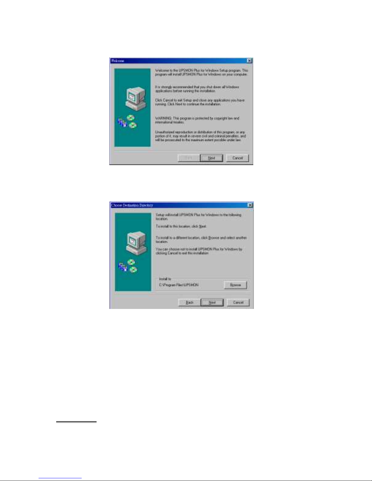
6. A windows labeled Welcome appears, please read and follow instruction written in the
window and click “Next”. (see Fig 5.3)
Fig 5.3
7. Select a location for installing program. Please read and follow instruction written in the
window and click Next. (see Fig 5.4)
Fig 5.4
8. Please read and follow instructions appearing in the window to complete installation of
the software.
5.3 Connecting interface cable
A series of interface kits is available for operation systems that provide UPS monitoring.
Each interface kit includes the special interface cable required to convert status signals from
the UPS into signals which individual operating system recognizes.
The interface cable at UPS side must be connected to REMOTE PORT, at computer side can
be either COM 1, COM 2, COM 3, COM 4 or USB port.
CAUTION: Use only the factory supplied or authorized UPS monitoring cable!
Page 27
14
5.4 The characteristics of software UPSMON
The communication port on the back of the UPS may be connected to host computer.
Through utilizing UPSMON software, the computer is allowed to monitor the status of the
UPS and controlling the operation condition of the UPS in some cases. These major
functions normally include some or all of the following:
To broadcast a warning message when power fails.
To close and save any open files before the battery is exhausted.
To turn-off the UPS.
Some computers are equipped with a special connector to link with the communication port.
In addition, special plug-in cord may be needed. Some computers may need special UPS
monitoring software. Contact your dealer for the details on the various interface Kits.
5.5 How to Use Software “UPSMON”
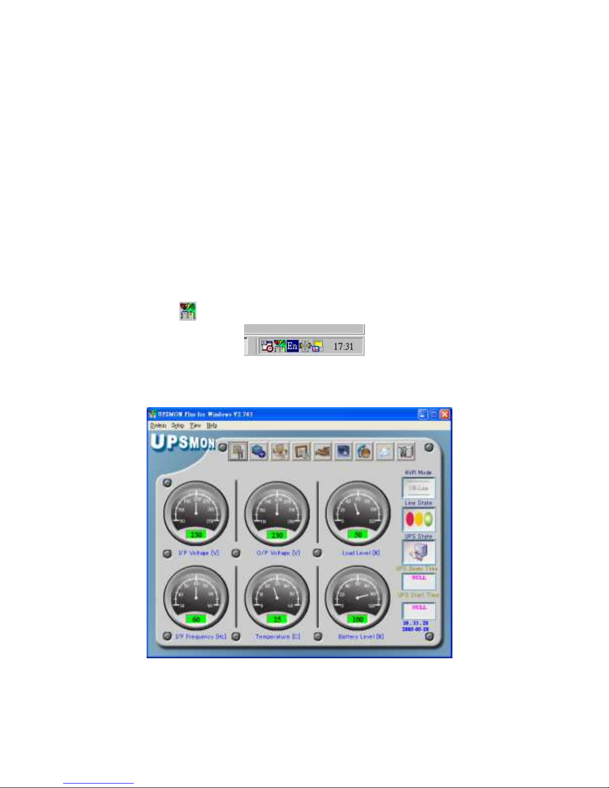
After you have completed installation of the software UPSMON, you can launch the
software by clicking on the icon on the Control Strip on your desktop (see Fig 5.5)
Fig 5.5
Then main menu of UPSMON appears as shown in Fig 5.6
Fig 5.6
The main menu contains tools and further feather for monitoring UPS operation and
controlling UPS. For details on each tool and function of UPSMON, please click on Help
Page 28

15
button on main menu of UPSMON.
Attention: UPSMON software and interface port function just available for model name
with “P” affix. The standard USB cable (or pin to pin D-SUB 9 pin cable) can be connected
between UPS REMOTE PORT and computer USB port (or COM port) for the UPSMON
series software.
6. Maintenance and storage
6.1 Maintenance
6.1.1. Keep the unit clean and vacuum the ventilation intake periodically.
6.1.2. Wipe with soft loose and damp cloth.
6.1.3. Check for loose and bad connections monthly.
6.1.4. Never leave the unit on an uneven surface.
6.1.5. Position the unit to allow at least 10 cm clearance between the rear panel and the
wall. Keep the ventilation intake open.
6.1.6. Avoid direct sunlight, rain and high humidity.
6.1.7. Stay away from fire and extremely hot location.
6.1.8. Do not stack materials on top of the unit.
6.1.9. The unit should not be exposed to corrosive air.
6.1.10 The normal operating temperature is 0-30℃.
6.2 Storage conditions
Store the UPS covered and upright in a cool and dry location, with its battery fully charged.
Before storing, charger the UPS for at least 6 hours. Remove any accessories in the
accessory slot and disconnect any cables connected to the computer interface port to avoid
unnecessary draining the battery.
6.3 To extend the storage
6.3.1. During the environment where the ambient temperature is -15 to +30 ℃ (+5 to +86
℉), charge the UPS‘s battery every 6 months.
6.3.2. During the environment where the ambient temperature is +30 to +45 ℃ (+86 to +113
℉), charge the UPS‘s battery every 3 months.
Page 29

16
7. Battery Replacement Procedure
The Batteries inside this UPS should last from between 2 to 3 years. If you suspect that the
batteries are weak, allow the UPS to charge the batteries for 24 hours and then test the
backup time. If the UPS still does not provide adequate backup time, follow the procedures
below to replace the batteries. Please read section 7.1 before proceeding the procedure in
sections 7.2
Notice: Please note that only Hot Swap models of UPS mentioned on this manual are with
this function of battery replacement.
7.1 WARNING
The battery must be replaced by a technical assistance department. In case of you choose a
different solution for the replacing of battery use only authorized personnel. The authorized
personnel must read the attached instructions.
CAUTION: Except for the battery, the unit contains no user serviceable parts. Repairs
should be performed only by factory trained service personnel.
CAUTION: A battery can present a risk of electrical shock and high short-circuit
current. The following precautions should be observed when working on batteries:
(1) Remove watches, rings, or other metal objects.
(2) Use tools with insulated handles.
CAUTION: Do not dispose of batteries in a fire. The batteries may explode.
CAUTION: Do not open or mutilate batteries. They contain an electrolyte which is
toxic and harmful to the skin and eyes.
CAUTION: When replacing batteries, use the same number and type of batteries.
7.2 Battery Replacement Procedure
The battery must be replaced by a technical assistance department.
To replace the battery is necessary open completely the ups. This operation is very dangerous
because there may be high voltage in the parts or components, also without ac line present,
ups turns off, cut battery. For this operation is necessary use only trained technical.
Page 30

17
Appendix A Troubleshooting
PROBLEM
POSSIBLE CAUSE
Solutions
UPS can't be turned
on
No lights on, no
warning sounds
Time of pressing the button is
too short
Keep pressing the button over 2
seconds
The UPS output has short
circuit or the UPS is
overloaded.
Turn off UPS and remove all
equipment to make sure there are
no problems on it or any internal
short circuit. Keep pressing
button over 2 seconds
“BACKUP mode”
Indicator is lit even if
the utility power is
present
The utility power voltage is out
of range
No solution because mode of
operation is correct
Poor connection to the input
utility power
Check the connection between
the UPS input outlet and utility
power
Fuse melted or circuit breaker
tripped
Replace fuse or reset circuit
breaker (you can find a spare fuse
for UPS at inlet of UPS).
The battery’s indicator
is lit & Buzzer keeps
beeping
The UPS is overloaded
Remove less needed equipment
Available time of the
batteries is too short.
Battery not fully charged
Keep UPS "ON" for over 24
hours to recharge the batteries
The UPS is overloaded
Remove less needed equipment
Batteries are near the end of its
service life
Contact the dealer or service
center for replacing batteries
The charger is out of order
Contact the dealer or service
center for help
The backup time is
about 4min. when the
load is light.
Green Mode function active.
The load is lighter than 30W,
please disable the Green Mode
function. (See section 3.2)
Page 31

18
Appendix B Specifications
Model
700 VA – 400 W
Voltage
230V
Frequency
50 or 60Hz +/-10% (auto sensing)
Output
Voltage
(on battery)
Simulated square wave output at nominal +/-5%
Frequency
(on
battery)
50 or 60Hz +/-1%
Voltage Regulation
(AVR)
AVR automatically increase output voltage 15% while
nominal –9% to –25% utility voltage be connected.
AVR automatically decrease output voltage 13% while
nominal +9% to +25% utility voltage be connected.
Transfer time
4 milliseconds (Typical)
Protection
and filtering
Surge Protection
420Joules(2x0V) / 225Joules(1x0V) , 8/20us
Unit Input
Fuse or Circuit breaker for overload & short circuit
protection
10 Base-T Cable Port
Network (UTP, RJ-45) compatible jacks
Overload protection
UPS automatic shutdown if overload exceeds 110% of
nominal at
60 seconds and 130% at 3 seconds.
Short Circuit
UPS output cut off immediately or input open
protection
Battery
Type
Sealed, Maintenance-free lead acid
Typical
Recharge
Time
6 hours (to 90% of full capacity)
Protection
Auto discharge protection
Back-up Time (a PC
with 15” monitor)
Relative to output power
Physical
Net Weight
Kg (lbs)
6.3
Dimension (mm)
W x
D x H
105 x 334 x 168
Alarm
Battery
Back-Up
Slow beeping sound (about 0.47Hz)
Battery Low
Rapid beeping sound (about 1.824Hz)
Overload
Continue beeping sound
Interface
RS232 or USB
Interface
Detect battery, Schedule UPS On/Off, AC input/ output
power status display
Environment
Operation
3,500m max, Humidity: 0%-95%(without condensation
formation), Temperature:
0-30℃
Audible noise
<40dBA (1 meter from surface)
Storage
condition
15000 meters max. elevation
 Loading...