

1 / 21
Safe Communications Ltd
March 2003
U
SER GUIDE
W
EATHERPROOF
«H
ANDS FREE» TELEPHONE
TLS 376 E
roupe
roupe
IS
Groupe Le Las
COMMUNICATING IN SAFETY

2 / 21
Safe Communications Ltd
March 2003
C
ONTENTS
1. PRESENTATION
1.1 GENERAL CHARACTERISTICS ................................................................................................................................ 3
1.2
CONTENTS OF THE PACKAGE ............................................................................................................................... 4
1.3 GENERAL DESCRIPTION OF TLS TELEPHONES ................................................................................................... 4
1.4 TECHNICAL CHARACTERISTICS OF TLS TELEPHONE ......................................................................................... 5
1.5 DESCRIPTION OF TLS 376 E TYPE TELEPHONES ................................................................................................. 7
2. INSTALLATION OF THE TELEPHONE……………………………………………………………….……….……………..8
3. LAYOUT OF THE TELEPHONE CARD ...................................................................................................................... 10
4. CONNECTION OF THE TELEPHONE SET ............................................................................................................... 11
5. USAGE OF THE TELEPHONE ................................................................................................................................... 12
6. VOLTAGE-FREE CONTACT FOR CCTV ACTIVATION ............................................................................................ 13
7. PROGRAMMING ......................................................................................................................................................... 14
8. MAINTENANCE ........................................................................................................................................................... 18
9.PROBLEM SOLVING .................................................................................................................................................. 18
12. SPARE PARTS LIST ................................................................................................................................................. 31

3 / 21
Safe Communications Ltd
March 2003
1.1 GENERAL CHARACTERISTICS
E
QUIPMENT FOR INDUSTRIAL SITES
« H
ANDS FREE » WEATHERPROOF
T
ELEPHONES SERIES
TLS 376 E
I
N THE DESIRE FOR CONSTANT IMPROVEMENT, THE INFORMATION
CONTAINED IN THIS DOCUMENT AND THE CHARACTERISTICS OF THE
EQUIPMENT MAY BE SUBJECT TO MODIFICATION WITHOUT PRIOR NOTICE
EUROPEAN STANDARDS
U
NITS BEARING THE CODE
“ CE ”
CONFORM TO EMC DIRECTIVE
EMC (89/336/EEC)
AND THE DIRECTIVE RELATING TO LOW VOLTAGE
(73/23/EEC)
FORMULATED BY
THE EUROPEAN COMMUNITY
.
UK BABT APPROVAL
UK BABT APPROVAL NO S/4130/3/Y/504612
REN
(RINGING EQUIVALENCE NUMBER) = 1
IMPORTANT NOTE
THIS PRODUCT CONFORMS TO IP66 WEATHERPROOFING CLASSIFICATION, I.E.
DUST-TIGHT AND PROTECTED AGAINST WATER-JETS AND HEAVY SEAS
WARRANTY IS ONLY VALID WHERE THE PRODUCTS ARE INSTALLED AND USED
STRICTLY IN ACCORDANCE WITH THE INSTRUCTIONS DESCRIBED IN THIS
MANUAL.
TO ENSURE EFFECTIVE WEATHERPROOFING OF THE TLS376 TELEPHONE, ON
INSTALLATION RE-INSTALLATION OR CLOSING AFTER OPENING ALL JOINTS
SEALS SCREW-HOLES AND CABLE ENTRY APERTURES MUST BE TIGHTLY
FASTENED OR BLOCKED OFF AND A COATING OF SILICONE SEALANT
APPLIED TO SEAL COMPLETELY ALL SUCH JOINTS AND APERTURES. THIS IS
ESPECIALLY IMPORTANT IN THE CASE OF TOP-ENTRY CABLES.
IF SUCH PRECAUTIONS ARE NOT TAKEN BY THE INSTALLER, OUR
WEATHERPROOFING GUARANTEE SHALL BE NULL AND VOID.
THE GUARANTEE WILL BE INVALIDATED IN THE EVENT OF A FAULT OR DAMAGE
RESULTING FROM AN EXTERNAL SOURCE OR DUE TO LACK OF ADHERENCE
TO USER INSTRUCTIONS.

4 / 21
Safe Communications Ltd
March 2003
1.2 CONTENTS OF THE PACKAGE
The equipment you have received comprises :
• a telephone set reference TLS376E1S
• a user manual
• cable entries Ref : GM208A10
• wall mounting kit Ref : GM208A12
1.3 GENERAL DESCRIPTION OF TLS TELEPHONES
The « Hands free » weatherproof telephones are Central Battery (CB) or Automatic Central
Battery (ACB) telephones without handset which can be used in centrally powered networks
or installations within the voltage limits permitted by our equipment (see technical
characteristics para.1.4 below).
These telephones are equipped with:
• A weatherproof loudspeaker
• A weatherproof and vandal-resistant « Electret » type microphone
• An electronic circuit card
• An on-line LED
• 1 button for S1 version
The telephone is housed in an enclosure comprising a front and back section, wallmounted
fixing internal to casing or optionally via external brackets. A hinge connects the two
sections, so that once installed, by removing a connecting pin from the hinge, the front
section containing all the electronics, can be removed.

5 / 21
Safe Communications Ltd
March 2003
FEATURES
• Pulse/Tone dialling.
• Automatic cleardown capability.
• Automatic answering capability or answering after a programmable number of rings.
• « Tone security protection » (microphone operable only after called party answers)
• Programming of stored numbers locally or via telephone line from any DTMF telephone.
• Chained numbers if the called number is busy or does not answer after a programmable
time.
• Modification of settings via telephone line from any DTMF telephone or via a maintenance
station, for example:
- Ringing type
- Ringing volume
- Loudspeaker volume
- Dialling type
- Automatic answer etc...
1.4 TECHNICAL CHARACTERISTICS OF TLS TELEPHONE
T
HIS MICROPROCESSOR-BASED PRODUCT, WHEN CONNECTED TO THE
TELEPHONE LINE, CARRY OUT AN AUTO-TEST BY TRANSMITTING AN AUDIBLE
SIGNALS
.
I
T IS EQUIPPED WITH MANY PROGRAMMABLE FUNCTIONS AND IS
FACTORY CONFIGURED FOR NORMAL USE
.
B
EFORE INSTALLATION, READ THIS MANUAL CAREFULLY TO BE SURE
THE FACTORY SETTINGS SUIT THE DESIRED USE
.
The « Hands free » telephone operates without any modification to PSTN circuits. For
perfect operation on a PABX, it is necessary to ensure that the following characteristics
conform to those of your switch.
In the event of incompatibility, software modifications can be carried out on request.
Contact the supplier for more information.
I
MPORTANT
NOTE

6 / 21
Safe Communications Ltd
March 2003
TECHNICAL CHARACTERISTICS
•
Ringing call voltage > 35 V RMS 25Hz or 50Hz
• Current in the telephone (off-hook position) 35mA (20mA minimum)
•
Voltage at terminals (on-hook position) 48V (24V minimum)
• Dialling system DTMF or Pulse
• Dialling tone Continuous tone
Frequency: 270 to 540Hz Detection time 2 sec.minimum
• Busy tone
Frequency: 300 to 500 Hz
Beep/pause sequence for more than 10 seconds. Detection time 4-10 sec.
Beep: 100 to 600 ms
Pause: 100 to 600 ms
• Distance ringing tone
Frequency: 350 à 500Hz
Beep/pause sequence until far-end off-hook
Beep: 0.2sec. to 1.6 sec.
Beep + pause sequence < 6 sec.
• End of conversation sequenced tone
Frequency: 300 to 500 Hz
Beep/pause sequence for more than 10 seconds. Detection time 4-10 sec
Beep: 100 to 600 ms
• End of conversation continuous tone
Frequency: 300 to 500 Hz or 760 to 840 Hz
Tone sequence for more than 10 seconds Detection time 6-10 sec.
• Call voltage transmitted by the switch
Frequency : 50Hz or 25Hz
Ringing duration : 1.5s ± 0.5s
Pause duration : 3s ± 2s
7 / 21
Safe Communications Ltd
March 2003
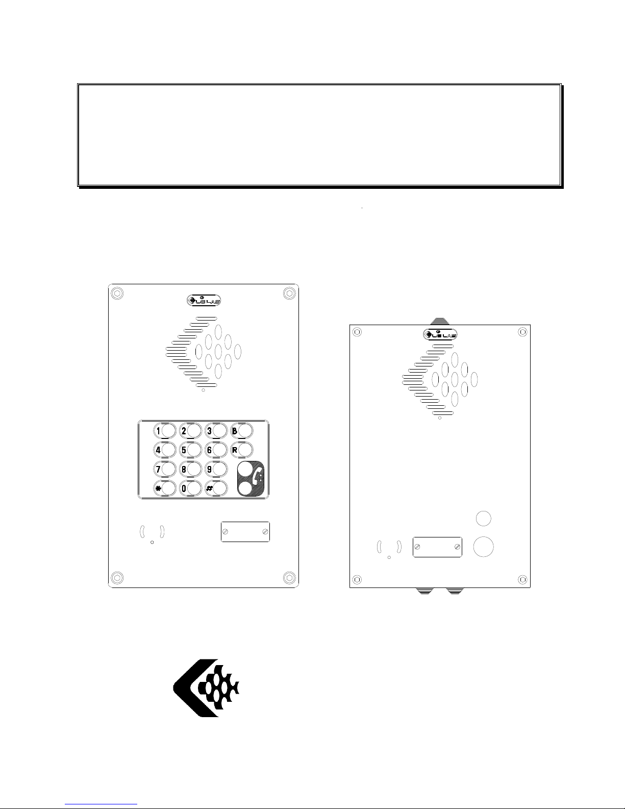
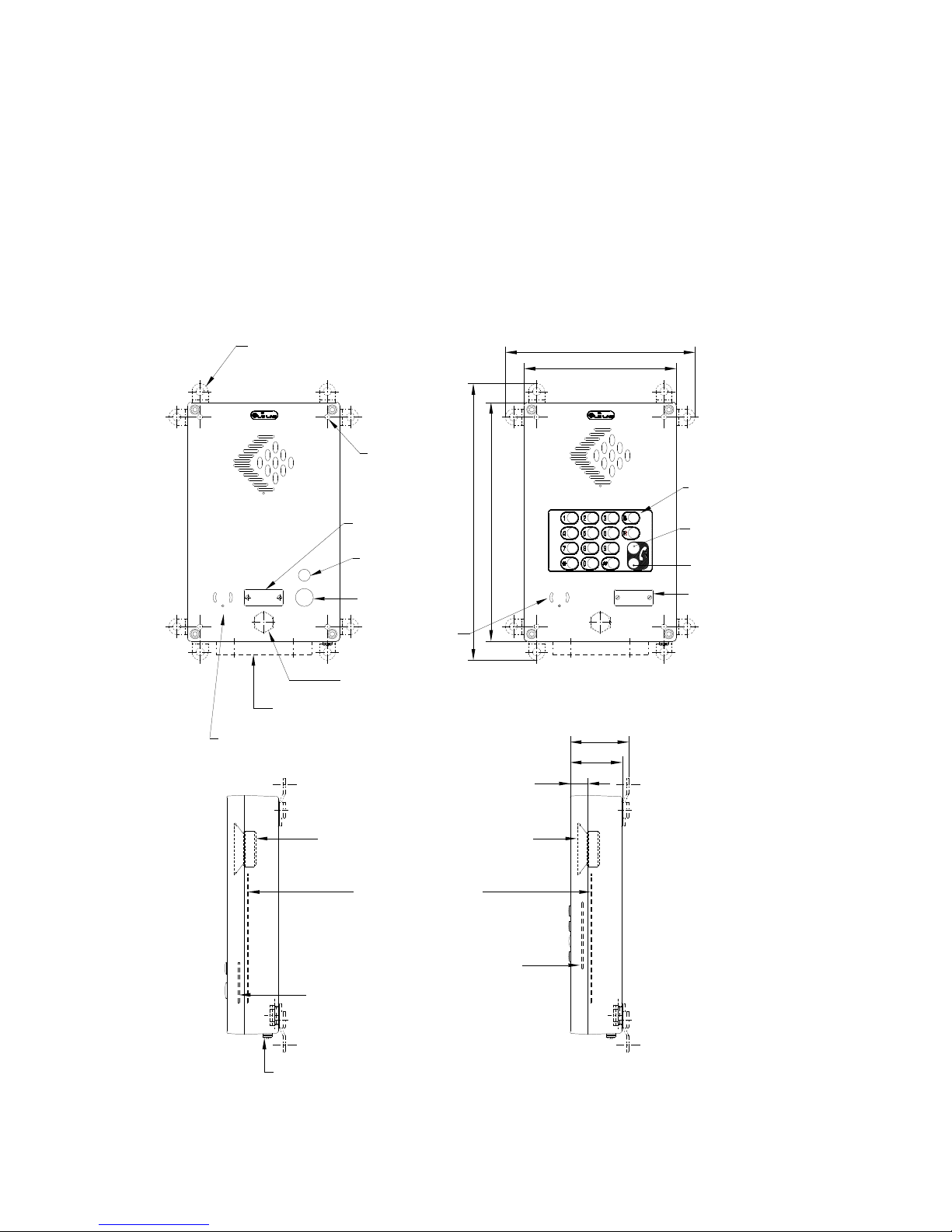
1.5 DESCRIPTION OF TLS 376E TYPE TELEPHONES
CB or ACB type weatherproof (IP66) wallmounted telephone set, comprising a light metal
back-case and front cover, protected by EPIKOTE paint.
The front cover which pivots at up to 180° and is removable, closes on to a weatherproof
seal via two screws acting as hinges and two hollow hexagonal retention screws or special
(optionally vandal-resistant) screws. A special key is needed to undo these screws.
roupe
REF: WK024CBT
SIGLE BUTTON CARD
REF: WK092CMA1
KEYPAD CARD
REF: CE124V11
15W / 50 OHMS
WEATHERPROOF LOUDSPEAKER
REF: WK140MLB
TELEPHONE CARD
EARTHING SCREW
IS
OPTION - 2 POSITIONS AVAILABLE
CABLE ENTRIES (NOT MOUNTED ON DELIVERY)
STOPPING PLUG
190
239
65
73
22
DAILLING KEYPAD
CALL BUTTON
LABEL
REF: GM208A13
TO CASE
FIXING INTERNAL
EXTERNAL FIXING BRACKETS
3
0
0
3
4
3
MICROPHONE
MICROPHONE
roupe
INDICATOR
ONE-LINE
INDICATOR
ONE-LINE
CALL BUTTON
LABEL
1 BUTTON
TELEPHONE SET TELEPHONE SET
FULL KEYPAD
8 / 21
Safe Communications Ltd
March 2003
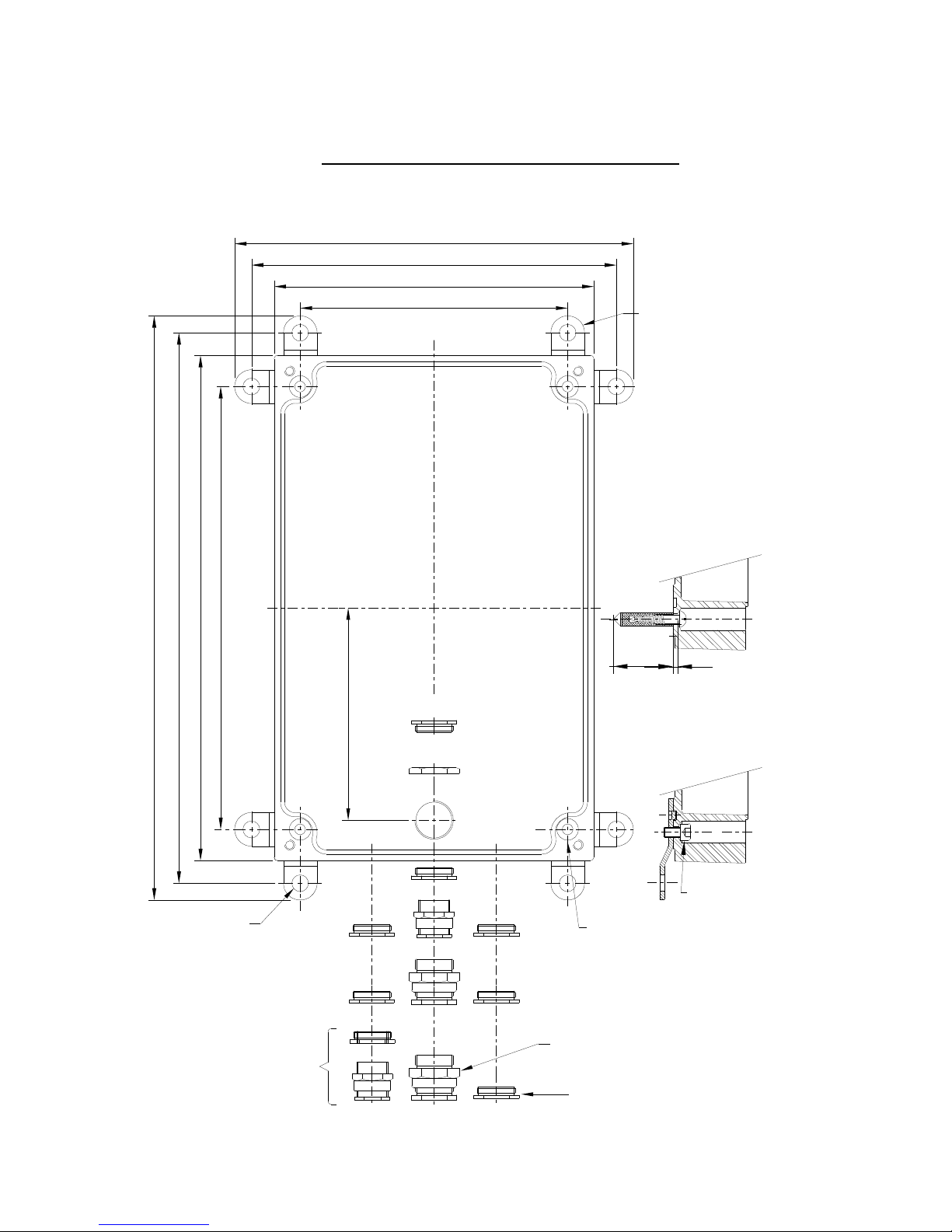
2. INSTALLATION OF THE TELEPHONE
2.1 INSTALLATION OF TLS 376 E MODEL CABLE ENTRIES ASSEMBLY
SCREW CHCM6/10
REF: GM337E2
EXTERNAL FIXING BRACKETS
DIAM.10
=
=
INTERNAL FIXING
OF BRACKETS
=
=
AND
+ +
+ +
++
AND
OR
OR
ADAPTOR
DIAM.8 TO DIAM.10 MAX
AND
SEALING PLUG
EMPTY GLAN FOR CABLE
DIAM.12 TO DIAM.14 MAXI
=
=
=
=
=
=
=
=
==
=
=
CABLE ENTRY GLAND
159
190
219
239
2
6
3
3
0
0
3
2
3
3
4
3
1
2
6
4 FIXING HOLES DIAM. 6.5
ON THE WALL
INTERNAL FIXING
>30
3
SEALING PLUG
ADAPTOR
+
OPTION
2 POSITIONS AVAILABLE

9 / 21
Safe Communications Ltd
March 2003
MIN
MAX
MIN
MAX
3. LAYOUT OF THE TELEPHONE CARD
3.1 FUNCTIONS AND JUMPER SETTINGS
L4
L3
L2
L1
C4
C3
C2
C3
C4
NC
LED+
LED-
BT
L2L1
BR1
M
I
N
M
I
C
V
O
M
A
X
ST1
R33
U
2
P2
P4
P1
W
K
1
4
0
M
L
B
HPHP+
MM+
LED+
LED-
C1
C2
P5
F
UNCTIONS
REF
JUMPERS
S
ENSITIVITY OF THE HANDS FREE MICROPHONE
Sensitivity up to 1m
Sensitivity up to 30cm
ST1
R
ÉCEPTION LEVEL ADJUSTMENT
Minimum setting : quiet location
Maximum setting : noisy location
NOTE : normal setting is carried out in factory (see drawing)
R33
MIN
MAX
10 / 21
Safe Communications Ltd
March 2003
4. CONNECTION OF THE TELEPHONE SET
4.1
OPENING THE TELEPHONE SET
To gain access to the circuit board, unfasten the 4 fixing screws in the front cover of the case
using Allen key No 5.
4.2
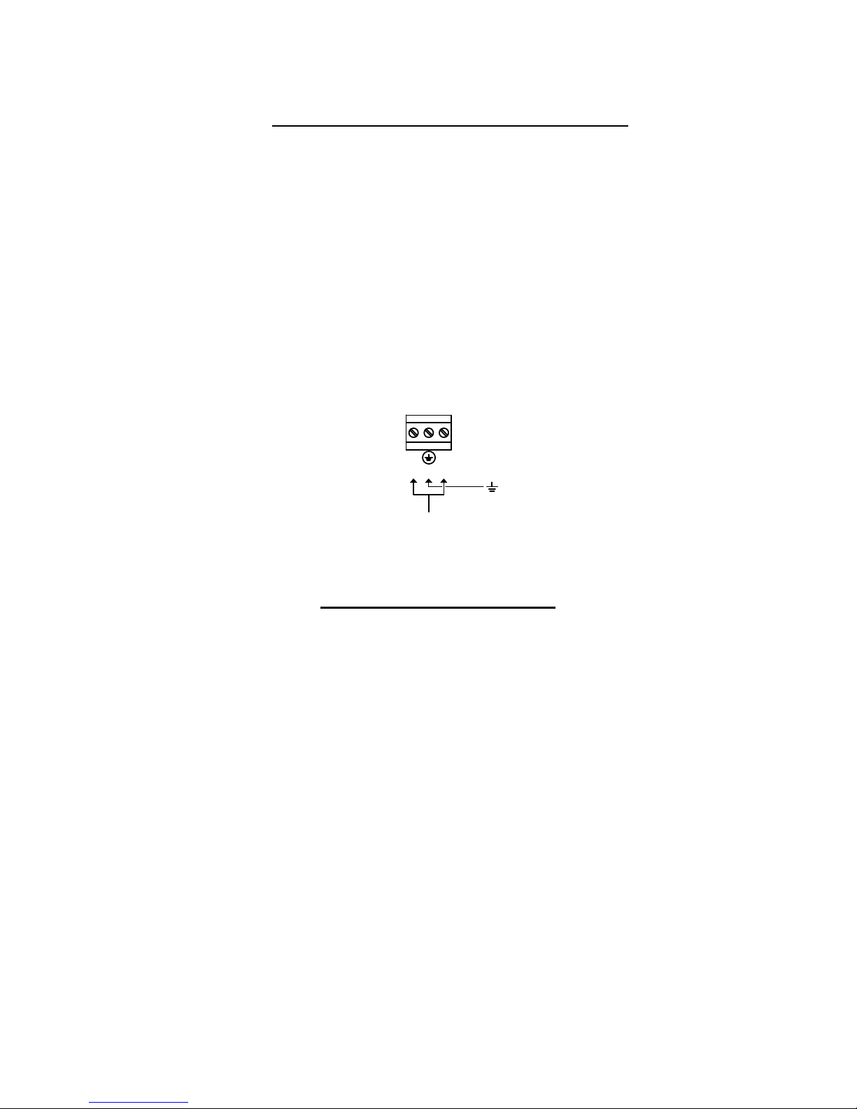
CONNECTION OF THE TELEPHONE LINE
The connection of the unit to the telephone line is carried out on printed circuit board
WK140MLB with the plug-in connector reference « BR1 ».
Connect the telephone line to the terminals L1 and L2 of the connector « BR1 ».
BR1
L2
L1
LIGNE TELEPHONIQUE
E
ARTHING THE TELEPHONE SET
Electrical earthing is carried out either externally via the earthing screw (situated at the
bottom of the case) indicated by the sign ⊥ or internally on the terminal ⊥ situated on the
« BR1 » connector on the telephone card WK140 MLB. A gas discharge tube is located on
the card, to discharge possible overloads to earth.

11 / 21
Safe Communications Ltd
March 2003
5. USAGE OF THE TELEPHONE
OPERATION : The button dials a pre-programmed telephone number (see chapter on
programming page 14)
H
OW TO MAKE OR ANSWER A CALL (MANUAL ANSWER
)
The red indicator shows.
When the called party answers, speak in front of the telephone from a distance of
approximately 20cm (8in).
At the end of conversation, to free the line :
The red indicator ceases to show.
H
OW TO ANSWER A CALL
(
A
UTOMATIC ANSWER
)
The telephone will anwer automatically and the red indicator will show,
the loudspeaker will be activated, but not the microphone.
When the telephone rings
The microphone is activated.
Having taken the call, speak in front of the telephone from a distance of
approximately 20 cm (8 in).
The red indicator shows.
The red indicator ceases to show
The red indicator shows.
.
Press the call button
P
RESS THE CALL BUTTON 2 SEC
.
OR ALLOW THE TELEPHONE TO CLEAR DOWN
AUTOMATICALLY
P
RESS THE CALL BUTTON
P
RESS THE CALL BUTTON
OR ALLOW THE TELEPHONE TO CLEAR DOWN
AUTOMATICALLY
2

12 / 21
Safe Communications Ltd
March 2003
6. VOLTAGE-FREE CONTACT FOR CCTV ACTIVATION
CAUTION ! FOR ANY APPLICATION INVOLVING CONNECTION TO AN EXTERNAL
POWERED DEVICE, INSTALLATION AND MAINTENANCE MUST ONLY BE CARRIED
OUT BY A QUALIFIED ELECTRICIAN.

13 / 21
Safe Communications Ltd
March 2003
7. PROGRAMMING
The TLS376E1S telephone is designed to facilitate programming remotly over a telephone
line. Programming is carried out using sequences keyed from a DTMF telephone, when
connected to the TLS376E1S telephone to be programmed.
7.1 PROGRAMMING CODES
IMPORTANT :
Before all programming, key the access code : *1234* (factory setting) or as
changed by the user (see function 12/13 below).
The acceptance sequence is a single beep if memory M0 (see function 18 below)
if empty or a single beep followed by the contents of Memory 0 folloxed by « * »
if memory M0 has been programmed.
Non-acceptance is indicated by « no-response » in which case it is necessary to
try again.
Proceed with programming as follows :
For each programming sequence below the telephone gives an acceptance/non-acceptance
sequence. The acceptance sequence is a mix DTMF tones (functions N° 1, 5 and 18 below)
or a single beep (all other functions).
In all cases the non-acceptance sequence is two beeps.
If the non-acceptance sequence is received, it is necessary to try again.

14 / 21
Safe Communications Ltd
March 2003
Function
No
Function Programming
code
1 AUTODIAL NUMBERS (If no chaining is required)
If chaining is required, use function N°5 instead (page 14)
During memory programming , the combination #11#
represents the recognition of a continuous tone with a
frequency of 440 Hz ± 100Hz (standard) before dialling.
PROCEED AS FOLLOWS :
Program button :
N = autodial number from 1 to 15 digits.
Program empty memory :
*5001*#11#N*
*5002*
2
TYPE OF DIALLING / CONFIGURATION
Although this equipment can use either loop disc or DTMF
signalling only the performance of the DTMF signalling is
subject to regulatory requirements for correct operation. It
is therefore strongly recommanded that the equipment is
set up to use DTMF signalling for access to public or
private emergency services. DTMF signalling also
provides faster call set-up.
For configuration, each function has a value as follows:
1/ DTMF dialling and automatic cleardown. 00
2/ For pulse dialling and automatic cleardown. Key the
combination :
*1000*
*1001*
3
LOUDSPEAKER VOLUME
V= volume from 1 to 9 (factory setting = 5)
*140V*
4
RINGING VOLUME
V= volume from 1 to 7 (factory setting = 7)
*160V*

15 / 21
Safe Communications Ltd
March 2003
Function
No
Function Programming
code
5
PROGRAMME A NUMBER CHAIN
It is possible to program a number chain, so that, for
autodial buttons, if the first number dialled is busy or does
not answer, the telephone will dial one or more alternative
number in a ‘chain’ until successful connection is made.
All telephone numbers programmed into the chain must
be different, no number may appear more than once.
THE STEPS TO TAKE ARE :
Program the main number in memory 1 and additional
numbers in memories 2-8.
Program an empty memory following the last number
entered, e.g., if two numbers are programmed, Memory 3
should be empty :
To program the interval between memory auto-dial
attempts
T1 between M1 – M2 and
T2 between M2 – M3, M3 – M4 etc… if necessary
These times are the intervals in the event of no-answer
before dialling the next number.
For T1 key :
TT is the time in seconds. If only one number TT=00
For T2 key :
If chaining 2 or several numbers, 2 choices are possible :
a) to hear what actually happens on the line : program
T1/T2 with even number *e.g. 30 sec.)
b) to mask what happens on the line (no-answer, busy
tone, ..) until the called party picks up, by simulating
ringing and flashing LED. On detection of speech from
the called party, a long beep announces to both parties
that the communication has been established, the LED
shows constant. For this, program T1/T2 with an odd
number (e.g. 31 sec.)
*500M*#11#N*
M (memory) =
1,2,….8 max.
N= Call number
up to 15 digits
The chain stops
at the
first
empty
memory.
*5003*
*20TT*
*21TT*

16 / 21
Safe Communications Ltd
March 2003
Function
No
Function
Programming
code
6
NUMBER OF RINGS BEFORE AUTOMATIC ANSWER
In the factory, the telephone is set to answer automatically
after 3 rings. To change this number, key :
NN= 00 to 99
NN= 03 factory setting (answer automatically after 3 ring
or manually by pushing the button)
NN= 00 automatic answer with no ringing (suitabel only for
programming)
NN= 99 No automatic answer (answer only manually by
pushing the button)
Important note :
Where 00 is programmed, both microphone and
loudspeaker are de-activated on auto-answer, where 0198 is programmed, the microphone is de-
activated on auto
answer (but the loudspeaker is active). The microphone
can be activated by pushing any butt
on. If, in this case,
the telephone receives programming signals (from an
operator or call-centre system, the loudspeaker is deactivated. It can be re-activated by keying the code
*
9901 *
*11NN*
8
MAXIMUM CALL DURATION
Length of conversation before automatic cleardown
Range XX=-00 No limit
XX=-99 99 minutes
Factory setting 4 minutes.
∗∗∗∗12XX∗∗∗∗
9
DURATION OF SILENCE BEFORE AUTOMATIC
CLEARDOWN
XX = 30 30 seconds (factory setting)
XX = 00 Does not clear down on duration of silence
XX = 99 99 seconds
Note : frequency tones are taken as silence.
*13XX*
10
TYPE OF RINGING MODULATION
XX = 00 Pure Frequency (factory setting)
XX = 01 3 Frequencies mixed
*15XX*
Function
No
Function
Programming
code

17 / 21
Safe Communications Ltd
March 2003
11
DURATION FOR WHICH BUTTON MUST BE
PRESSED CONTINUOUSLY BEFORE TELEPHONE
GOES « ON LINE »
XX = 00 Immediate (factory setting)
XX = 99 9.9 seconds
*17XX*
12
PASS CODE (1)
First two digits of programming pass-code
XX = 12 (factory setting)
XX = 10 (range)
XX = 99
*30XX*
13
PASS CODE (2)
Last two digit of programming pass-code
Note : The pass-code is a 4 digit code (from 1000 –
9999).
It is input in two halves, as described above.
XX = 34 (factory setting)
XX = 10 (range)
XX = 99
*31XX*
14
DURATION FOR WHICH BUTTON MUST BE
PRESSED CONTINUOUSLY FOR CLEARDOWN TO
TAKE PLACE
XX = 20 (factory setting)
XX = 00 (range) no clear down
XX = 99 9.9 seconds
*32XX*
15
MINIMUM TONE RECOGNATION/CLEARDOWN
FREQUENCY
XX = 25 250Hz (factory setting)
XX = 00 0Hz (range)
XX = 99 990Hz
*34XX*
16
MAXIMUM CLEARDOWN TONE FREQUENCY
XX = 50 500Hz (factory setting)
XX = 00 0Hz (range)
XX = 99 990Hz
*35XX*

18 / 21
Safe Communications Ltd
March 2003
Function
No
Function Programmin
g code
17
RETURN TELEPHONE TO FACTORY SETTING
ERASE MEMORIES
XX=00 Acknowledgement from telephone after about
1.3s
XX = 02 Erase memories M0 – M9
*98XX*
18
PROGRAM TELEPHONE ID
This is a code of up to four digits which should be
programmed into memory M0.
The telephone will automatically transmit this ID code
followed by « star » (*) on receipt of thec command code
*0600* from a central system.
N = telephone ID up to 4 digits
*5000*N*
7.2 OPERATIONAL COMMAND CODES
Function
No
Function Programming
code
1
REQUEST TELEPHONE ID
This code is transmitted by the central system to
determine the identity of a telephone calling the centre.
The telephone will respond with its telephone ID (see
programming code 18 above)
*0600*
2
AUTOMATIC CLEARDOWN
At the end of a call without access to programming, the
central system or operator can effect an automatic
cleardown by transmitting this code :
However, if the call has included access to programming,
automatic clear-down is carried out by transmitting this
code :
*0990*
*9900*
3
TEST MICROPHONE AND LOUDSPEAKER
Acknowledgement from telephone : 1 sec. Transmission
of frequency of 1244Hz
Followed by : 1sec. Transmission of frequency of 622Hz
Note : After test, the loudspeaker is switched off.
To re-activate the loudspeaker :
To conclude the test :
*9700*
*9901*
*9900*

19 / 21
Safe Communications Ltd
March 2003
8. MAINTENANCE
The TLS376E1S telephone requires little maintenance to remain in excellent operational
condition.
Carry out the following maintenance if necessary.
E
XTERNALLY
Clean using a dampened soft cloth to remove dust and dirt. For grease, a little soap may be
used.
If you use a high pressure hose (preferably 50 bar) do so from a distance of about 1.50m
(5ft) from the telephone.
I
NTERNALLY
The telephone requires no internal maintenance. Do not insert any fluid into the telephone
set.
W
EATHERPROOFING
At least once a year and otherwise whenever closing after opening check thoroughly the
effective weatherproofing of the joints, seals and apertures and state of the silicon sealant
and repair or replace as appropriate (see Note – page 4).
GRAFFITI
Where graffiti have been sprayed or painted on to the surface of the telephone and cannot
be removed the telephone may be re-painted using Epoxy paint colour orange RAL2008 or
BROWN RAL8007. The surface of the telephone should first be washed with a detergent
and rubbed down with an abrasive.
9. IN THE EVENT OF A PROBLEM
Before consulting the maintenance service, we advise you to check the following points:
P
ROBLÈM WITH LINE CONNECTION OR DIALLING
:
• Check telephone line correction on the connection terminal (see page 14)
• Check the button is not jammed by foreign object.
T
RANSMISSION PROBLEM
• Check the setting of jumper ST1 (see page 13)
• If transmission if weak, check that the microphone holes are not blocked by a foreign
object.
R
ECEPTION PROBLEM
• If transmission if weak, adjust the reception to the level required.

20 / 21
Safe Communications Ltd
March 2003
10. SPARE PARTS LIST
• Telephone board WK 140 MLB
• Single button card for TLS376E1S WK024CBT
• 50 Ω - 15 W Loudspeaker CE 124 V11
• Electret microphone CE 515 V2

21 / 21
Safe Communications Ltd
March 2003
GROUPE LE LAS
-
PARIS
REGION PARISIENNE
34/36 RUE ROGER SALENGRO
F 94134 FONTENAY SOUS BOIS
Tel : 33 01 48 76 62 62
Fax : 33 01 48 76 83 04
Internet : www.lelas.fr
E-mail : lelas@wanadoo.fr
BELGIQUE
BD BRACOPS 205/1
B. 1070 BRUXELLES
Tel : 00 32 25 22 83 66
Fax : 00 32 25 27 83 14
ENGLAND
SAFE COMMUNICATIONS LTD
BANK HOUSE - SOUTHWICK SQUARE
SOUTHWICK
U.K BRIGHTON W. SUSSEX BN 42 4 FN
Tel: 00 44 12 73 87 14 00
Fax: 00 44 12 73 59 66 00
E-mail: safe.communications@virgin.net
ITALY
TELEINDUSTRIA SRL
VIA V. FOPPA, 4
I. 20144 MILANO
Tel : 00 39 024 98 39 91
Fax : 00 39 024 98 40 40
Sales@teleindustria.it
 Loading...