

Group DEP Thermodynamic Box Installation Instructions And User Manual

Installation instructions and user manual V1.5 1
www.groupdep.com thermodynamic@groupdep.com
Thermodynamic
Box
Operation and Installation Manual
Authorised sole distributor for Magic Thermodynamic Box Limited

Installation instructions and user manual V1.5 2
www.groupdep.com thermodynamic@groupdep.com
INDEX
1 INTRODUCTION 3
2 GENERAL SAFETY WARNINGS 4
3 OPERATING PRINCIPLE 5
4 TECHNICAL SPECIFICATIONS 6
5 INSTALLATION 7
5.1 INSTALLING THE LITTLE MAGIC THERMODYNAMIC BOX 8
5.2 INSTALLING THE THERMODYNAMIC PANEL 9
5.3 REFRIGERATION CONNECTIONS 11
5.4 SIGHT GLASS 12
5.5 HYDRAULIC CONNECTIONS 13
5.6 TEMPERATURE SENSOR 17
5.7 ELECTRICAL CONNECTIONS 17
5.8 PRESSURE TEST WITH NITROGEN 17
5.9 VACUUM TEST 18
5.10 FILLING OF THE REFRIGERANT CIRCUIT 18
5.11 DRAINING & BLEEDING 18
5.11 TURNING THE SYSTEM ON 19
6 DIGITAL CONTROLLER SETTING 20
7 REPAIR AND MAINTENANCE 22
8 TROUBLESHOOTING – Guidance Values 23
9 TROUBLESHOOTING - Electrical Wiring 24
10 TROUBLESHOOTING GUIDE 25
11 MANUFACTURERS INSTALLATION PACK 26
12 GENERAL CONDITIONS OF WARRANTY 27
Installation instructions and user manual V1.5 3
www.groupdep.com thermodynamic@groupdep.com
1 INTRODUCTION
Group DEP is excited to bring the Thermodynamic water heating system to Australia and New Zealand. We
have worked extensively on licensing the product and we feel that it is unmatched in its efficiency by any
other renewable energy product. Group DEP is the authorized sole distributor for Little Magic
Thermodynamic Box Ltd. The Thermodynamic Box is designed to heat a domestic hot water cylinder up to
60°C. The maximum temperature is influenced by the individual installation, pipe lengths and insulation. It
uses an exterior aluminium panel to absorb energy from the ambient air. The heat exchanger is a low
resistance type manufactured from stainless steel plates. The pump used is of a composite material,
extremely light and fully compatible with potable water applications. The product has a reciprocating
compressor for quiet and efficient performance. This box has a timer with a 1 minute start delay for
protection of the compressor. With these features the Thermodynamic Box is designed to have a long,
trouble free life.
The Thermodynamic Box has integral safety devices to protect the product from internal and external
faults. An adjustable digital thermostat controls the water temperature.
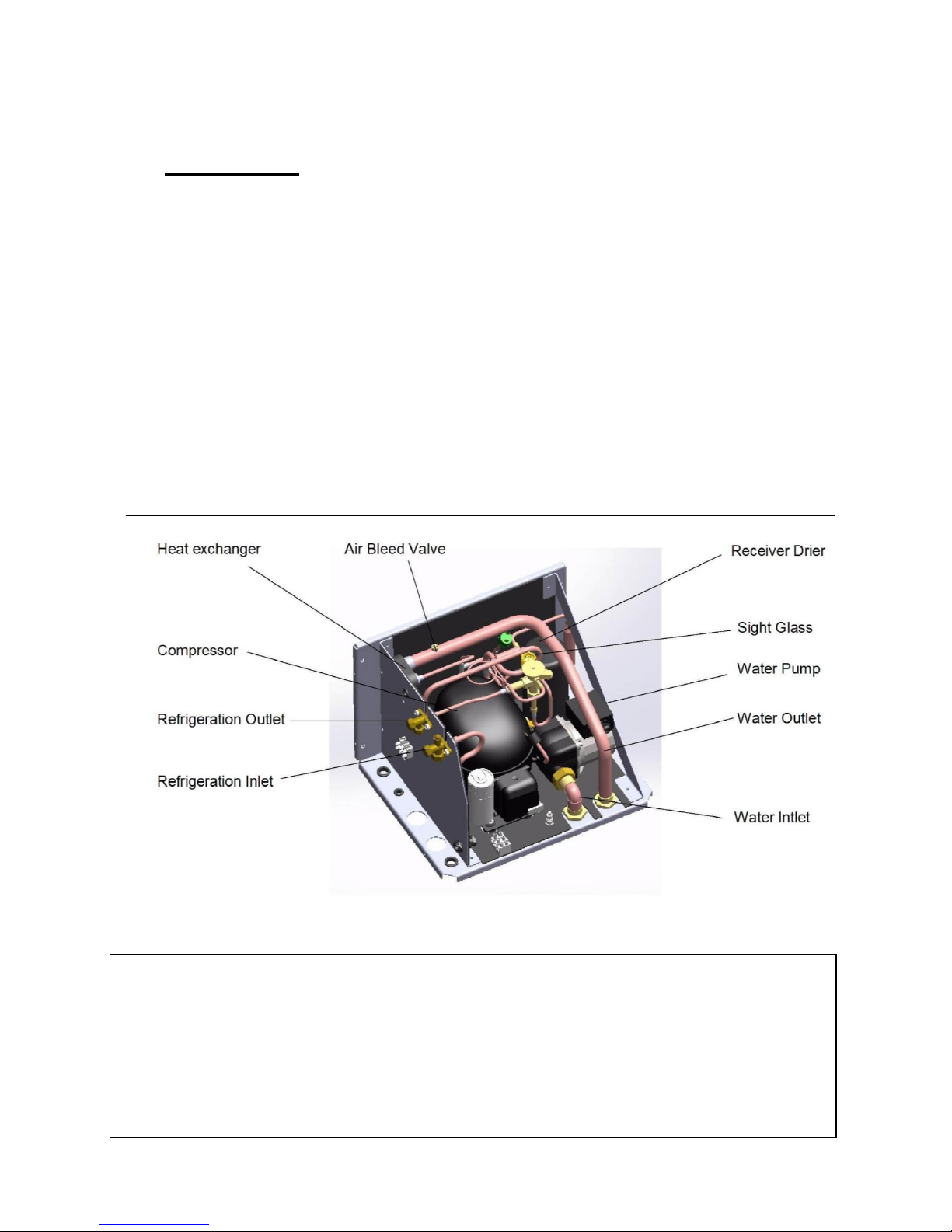
Fig. 1 INTERNAL LAYOUT OF LITTLE MAGIC THERMODYNAMIC BOX
IMPORTANT
This product is not intended for use by persons (including children) with reduced physical, sensory or
mental capabilities, or lack of experience and knowledge, unless they have been given supervision or
instruction concerning the use of the product by a person responsible for their safety.
Children should be supervised to ensure that they do not play with the product.
This Product must be installed by a fully qualified Refrigeration plumber.
Installation instructions and user manual V1.5
www.groupdep.com
2 GENERAL SAFETY
WARNI
To avoid injury to the user
o
followed. Incorrect operati
o
The installation is the respo
n
equipment carefully before
regards damages deriving f
r
detailed here.
Ask a suitably qualified
refrigerant
may cause gas or water lea
ks
Do not install the equipme
n
equipment: areas with corr
o
fluctuations, places with str
other special environments
.
The electrical connection s
h
standards guide.
Sufficient space should be
al
the connections of pipes an
The Thermodynamic Box s
h
installation. If turned on i
ts
The support surface shall b
e
unit without increasing noi
se
Hard waters (CaCO3 conte
n
the system. It is recommen
d
HEALTH & SAFETY: Care sh
o
the product. Check the wei
gh
for the safety of the install
er
product and in particular th
location and the mounting
structu
withstand the additional lo
a
equipment to ensure there
thermodynamic@groupdep.com
NGS
r damage to the product the instructions within
n will invalidate the warranty.
sibility of the purchaser. Read the information
su
installing and using it. The manufacturer declin
es
om an incorrect installation and a failure to foll
o
gas plumber to install this product as
an i
and invalidate any warranty.
t in the following places as they will lead to a m
al
sive gases, factories where the electrical voltag
e
ong electromagnetic waves, places with inflam
m
ould be carried out in accordance with that spe
cified
lowed for the installation and maintenance of t
h
d wiring.
ould always remain in a horizontal position duri
n
side the compressor should be checked for sign
s
flat, bear the weight of the unit and be ready f
o
or vibrations.
t >200 ppm) may produce obstructions due to t
h
ed to use a descaler in the hydraulic circuit.
uld be taken when moving
t before any lifting. This is
and customer. Ensure the
e box are installed in a safe
re is adequate to
ds. Take care when moving
is no damage to the equipment or existing stru
ctu
4
the manual must be
pplied with the
any responsibility as
w the instructions
ncorrect installation
function of the
experiences wide
able materials or gases,
in the Australian
e product including
g transport and
of leakage.
r the installation of the
e lime deposits inside
re and fittings.
Installation instructions and user manual V1.5 5
www.groupdep.com thermodynamic@groupdep.com
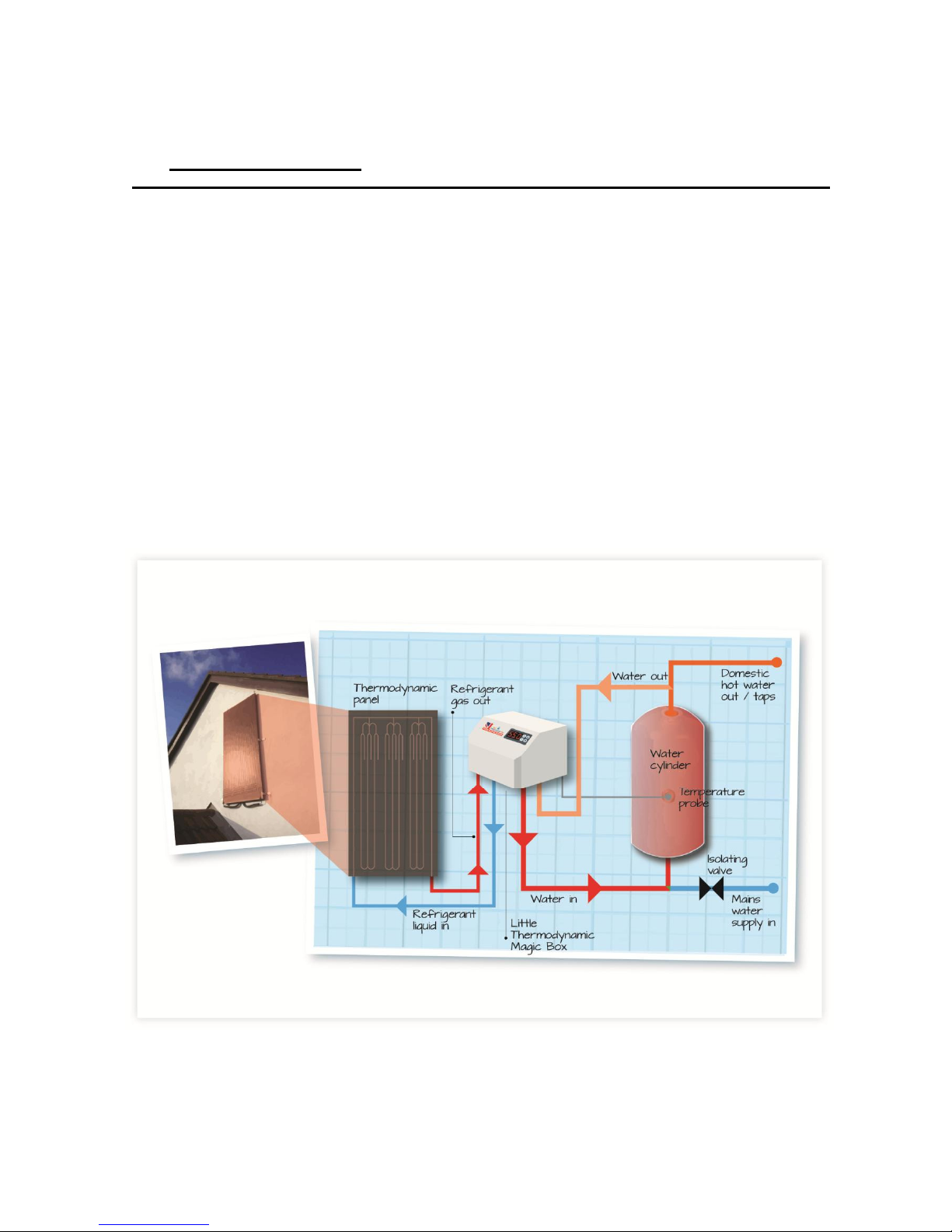
3 OPERATING PRINCIPLE
The Thermodynamic Box works on the principle of thermodynamics. It is the process of heating water in a
cylinder by using a refrigerant liquid which is circulated in an external panel (evaporator) that absorbs
energy from the ambient air. This energy excites the liquid which turns it into a gas. This gas is compressed
to create heat which is transferred to the water via the heat exchanger. Due to the uniqueness of the
direct gas evaporation principle the external thermodynamic collector can absorb heat during the day and
night in all climatic conditions (rain, cloud, sun and wind).
The Thermodynamic Box operates with sealed pressurised systems and vented systems.
When the Thermodynamic Box is added as a retrofit to an existing cylinder the existing boiler should be
fully serviced. As the box is set at 60oC this produces adequate protection from legionella.
There must be a temperature reduction valve fitted in accordance with Australian Standards.
Fig 2: Little Magic Thermodynamic Box Operating Principle Simplified Schematic

Installation instructions and user manual V1.5 6
www.groupdep.com thermodynamic@groupdep.com
4 TECHNICAL SPECIFICATIONS
TECHNICAL SPECIFICATIONS
Mean thermal capacity (only thermodynamic) (W)
840W to 2200W
Min to Max Mean power consumed
(thermodynamic) (W)
350W to 650W
Typically 450W
Voltage / frequency
220-240V, 50Hz
Atmospheric temperature range (ºC)
-10°C to 50°C
Hermetic System
Refrigerant fluid and charge
R134a, 0.70kg
Max. Hot water temperature (ºC)
60oC
Unit Dimensions (height x width x depth) (mm)
310mm x 420mm x 345mm
Packaging dimensions (height x width x depth)
410mm x 511mm x 442mm
Thermodynamic box weight (kg)
31 kg
Maximum water circuit working pressure (bar)
8 bar
Cold water input conne
ctions (") /Hot water output
connections (")
¾” & ¾”
Thermodynamic panel weight (kg)
6.2kg
Thermodynamic Panel Dimensions
(height x width x depth) mm
1700mm x 800mm x 25mm
Thermodynamic panel input/ output c
onne
ctions
(thread) SAE(”)
¼” & 3/8”
Thermodynamic unit i
nput/ output conne
ctions
(thread) SAE(”)
3/8” & ¼”
R134a refrigerant gas
Fig 3

Installation instructions and user manual V1.5 7
www.groupdep.com thermodynamic@groupdep.com
5 INSTALLATION
It is essential that correct licenses are held to install and connect the panel to the Thermodynamic Box. All
personnel carrying out installation, maintenance or servicing of stationary refrigeration, air-conditioning or
heat pump equipment that contains or is designed to contain F-Gas refrigerants must hold the relevant
designated qualifications stated in the Australian Standards guidelines.
The plumbing work must be carried out by a plumber who is qualified to Level 3. Where necessary the
plumber must hold an Unvented Hot Water Certificate recognized by Competent Person Schemes (CPS)
approved to offer self-certification under Approved Document G.
Inside Australia the installation needs to be carried out in accordance with the country’s local regulations.
Installation Steps:
1. Install the Thermodynamic Box
2. Install the Thermodynamic Panel
3. Refrigeration connections
4. The sight glass
5. Hydraulic connections
6. Temperature Sensor
7. Electrical connections
8. Pressure test during the installation with nitrogen
9. Vacuum test during installation
10. Filling of the refrigerant circuit
11. Draining & bleeding of the hydraulic circuit
12. Temperature reduction valve
13. Turning the system on
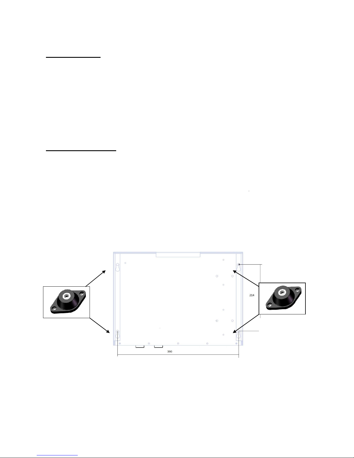
5.1 INSTALLING THE THERMODYANAMIC BOX
Siting location
• Make sure the fixing points and fixing methods will take the weight of the
Thermodynamic Box. Please refer the Fig.2 for the fixing location of the unit.
• The Thermodynamic Box must be installed in horizontal position.
• The equipment shall not be installed in a place where it exposed to corrosive gases, major electrical
fluctuations, high electromagnetic field, inflammable materials or other hazardous areas.
• Minimum pipe diameter of 22mm should be used in the hydraulic system between the
Thermodynamic Box and water cylinder.
Installation instructions and user manual V1.5
www.groupdep.com
Handling the unit
The unit must be transported and
mo
Before handling the unit, check its
w
During handling care should be tak
en
order to avoid damage.
Installation of the unit
Step 1: Carefully remove the outer
Step 2: Fix the unit to a suitable w
all with
any possible vibration nois
e
(see end of manual)
For maximum efficiency the Therm
o
reduce pipework length and minim
i
cylinder should be insulated.
Anti-vibration
mounts
Fig.4 Positi
on
thermodynamic@groupdep.com
ved in the horizontal position and should nev
er
eight (Section 4 “Technical Specification” of thi
s
to ensure it shall not be subjected to sudden
m
casing of the unit to gain access to the wall fixin
g
four screws. Anti-vibration mounts with
should be used. These are included in the
optional
dynamic Box should be installed as close to the
c
ze bends. It is recommened that Pipework
within
s of fixing holes with M8 anti vibrations moun
ts
8
be turned over.
manual).
ovements or impact in
points.
M8 bolts to minimize
Installation kit.
ylinder as possible to
a metre of the
Anti-vibration
mounts
Installation instructions and user manual V1.5 9
www.groupdep.com thermodynamic@groupdep.com
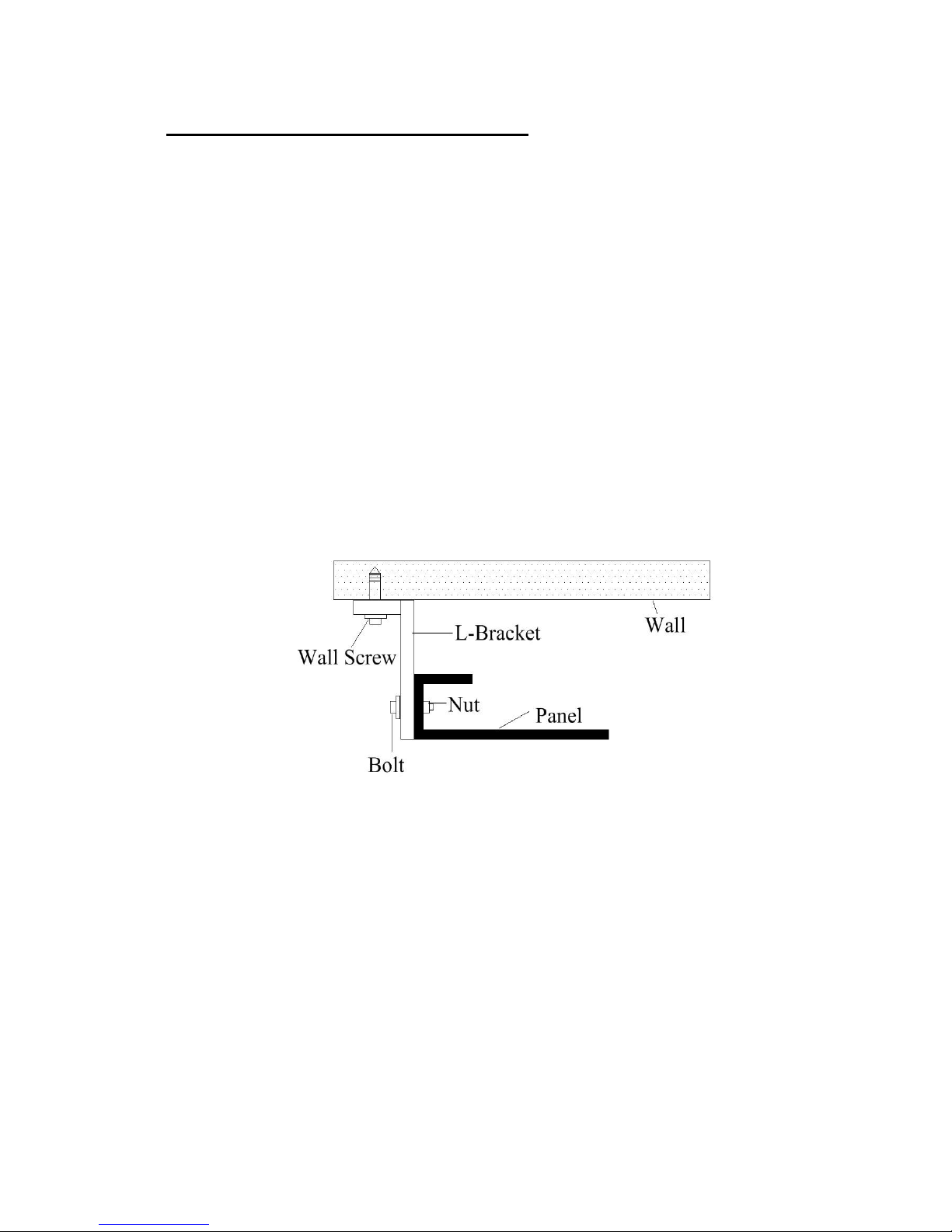
5.2 INSTALLING THE THERMODYNAMIC PANEL
• The panel can be installed, using the supplied brackets, to an exterior wall. If the panel is installed
on a roof it should be fixed in accordance with Australian Standards. Compliance is the
responsibility of the installer.
• Fix the evaporator panel in a vertical (portrait) position for the best performance, horizontal
(landscape) is also valid, with the inlet pipes situated on the lower part as per the figure 7. The
refrigeration grade copper pipes (3/8ths and ¼) connect the exterior panel to the Box.
NOTE: Care must be taken to avoid bending the panel and the refrigerant pipes.
• The system is pre-charged with 700gms of refrigerant gas for 8m of pipe length between the
Thermodynamic Box and the Panel. The pipe length can be extended up to 15 metres however for
every extra metre length of pipe 50g of refrigerant gas should be added.
• To fix the panel use the supplied brackets, fixing screws or bolts. Please see the picture below for
fixing the panel on the wall.
Fig. 5 Thermodynamic Panel Fixings
• The panel can be located on any facing aspect. Performance differences would only be applicable
during daylight hours.
• For increased performance, the panel can be installed parallel to the prevailing wind, allowing the
air to pass freely over the surface of the panel.
NOTE: If installed on the roof or similar then snow loads for the area should not exceed 1.0N/m2
and should not be exposed to wind velocities greater than 28m/s.
• Connection of the panel: Gas outlet (fig. 9) is connected to the gas inlet of the unit and liquid
inlet (fig. 9) is connected to the liquid outlet of the unit.
 Loading...