

Group3 DTM-333 Operation Manual
GROUP3 TECHNOLOGY LIMITED WWW.GROUP3TECHNOLOGY.COM
DTM-333
Digital Teslameter
Operations Manual
Group3 reserves the right to change the specifications at any time without notice. 01082018-D333
Group3 Technology Ltd.
2 Charann Place, Avondale
Auckland 1026 , New Zealand
PO Box 71-111, Rosebank, Auckland 1348, New Zealand
Phone: +64 9 828 3358
Fax: +64 9 828 3357
Email: sales@group3technology.com
Web: http://www.group3technology.com
Calibration/Repair: www.group3technology.com/service
Made in New Zealand

GROUP3 TECHNOLOGY LIMITED WWW.GROUP3TECHNOLOGY.COM
INTRODUCTION
Thank you for purchasing and using a Group3 Digital Teslameter. We hope you will join the many thousands of users worldwide who are
enthusiastic about our products.
The DTM-333 is a 3-Axis, 3-Channel Digital Teslameter product of Group3. It uses the same technology with that of a DTM-133 but in a 3channel, 3-axis configuration. On top of that the external mechanical switches have now been upgraded to give users the ease of operating
it using the touch screen interface of a robust 7-inch industrial tablet. It runs on a Group3 custom-made android-based app which gives a
smooth and user-friendly operation that boast a touch screen interface to operate the DTM.
Another feature of the DTM-333 is its data logging capability where user can do their data gathering on the DTM itself and saves the
output CSV file on to an external memory drive such as a USB drive or hard disk. This eliminates the need for a separate computer terminal
and software to do a data log of a session such as field mapping of a magnet.
The DTM-333 also boast of a graphical display of all 3 axis/channel simultaneously. Users can see the behavior of a session instead of just
looking at the field reading. The graphical display lets the user monitor visually if there are sudden or abrupt changes in the field of any of
the three fields over a period. The time and field range are configurable depending on the user’s preferences. The vector sum of the 3 fields
is calculated and shown on the HOME tab and at the GRAPH tab.
Using a custom-built 3DT-132 probe is the perfect probe to measure fields in three directions (axis mode) simultaneously. If each unit will
be use separately or individually as in channel mode, three (3) MPT-132 or LPT-132 probes can also be use.
Group3 has been designing and building magnetic field measuring equipment since 1983. We are constantly upgrading our products and
support documentation. We welcome input from our customers, so if there are aspects of the instrument which you particularly like, or
which you would like to see improved, please contact your Group3 supplier (see back page for a complete list) or Group3 directly with your
suggestions to sales@group3technology.com .
The Group3 website, www.group3technology.com contains details of all our products. This site is regularly updated, so check it from
time to time to learn about recent developments.
GROUP3 TECHNOLOGY LIMITED WWW.GROUP3TECHNOLOGY.COM
DTM-333 Digital Teslameter Features
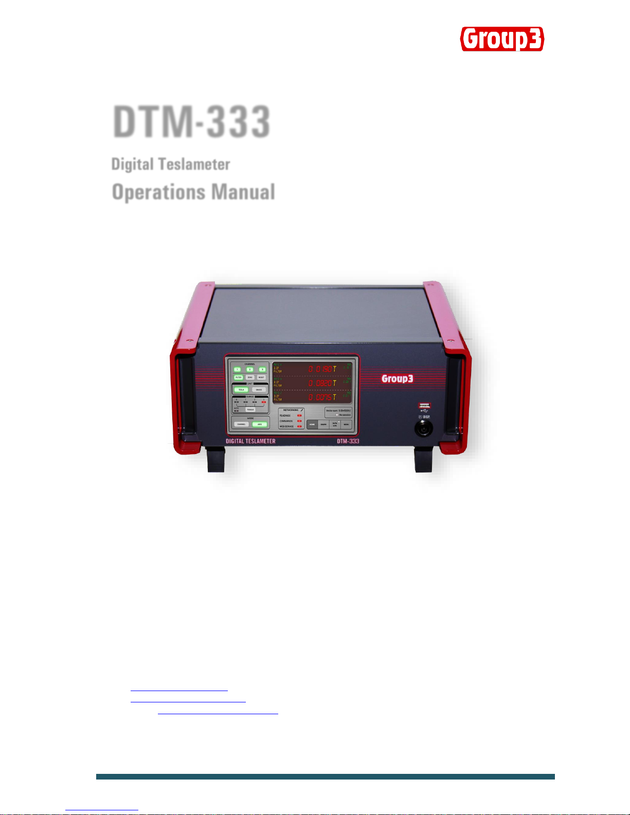
FRONT PANEL
1 Power Button Press to turn ON and OFF the unit
2 HOME Tab Touch to show the Main Readings screen
3 GRAPH Tab Touch to show and access Graph and configure controls
4 DATA LOG Tab Touch to do data logs and change Date/Time
5 MENU Tab Touch to access the DTM’s manual controls
6 NETWORKING Touch to access Ethernet networking controls
7 LED Buttons Touch to turn ON/OFF the Readings/Commands/Web Service controls
8 TOGGLE Button Touch to change the DTM range
9 FILTER Button Touch to turn ON/OFF the filter. Lights up a green color when ON.
10 ZERO Button Touch to set the reading to Zero. A green color indicates current unit.
11 RESET Button Touch to reset the unit.
12 UNIT Button Touch to choose either Gauss or Tesla.
13 Channel, Range & Filter Indicates the Channel/Axis, current range and filter status
14 Field Indicator Shows the measured magnetic field and temperature reading
15 Maximum Field Indicator Shows the maximum field measured
16 Session Indicator A GREEN light shows when an ongoing session. Otherwise, LED is in RED
17 USB Port Insert your USB Drive or memory stick to save data log files
18 Mounting Cheeks Panel mounting to a 19” rack. (optional)
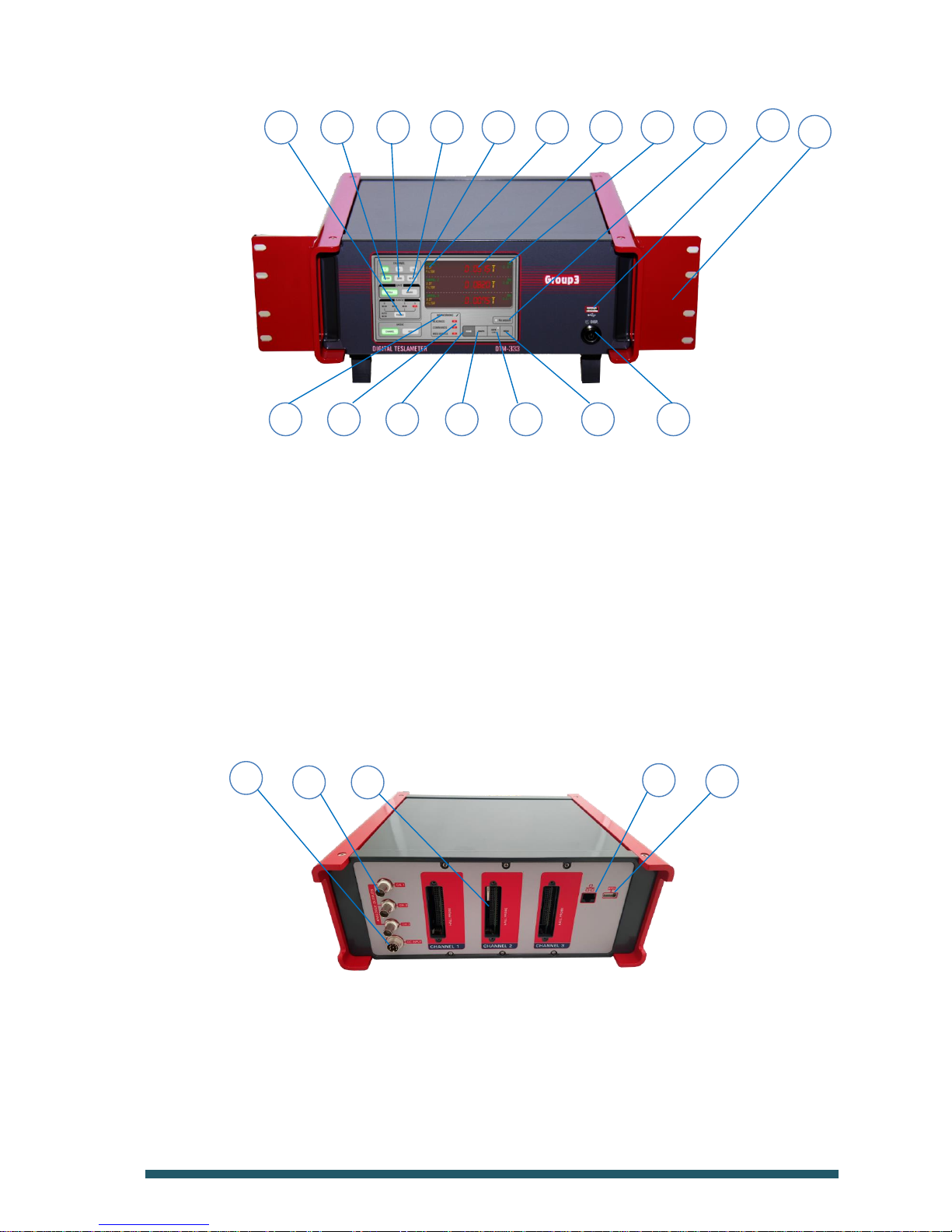
REAR PANEL
1 DC Input Socket Attach the supplied DC Power supply and lock to secure the power plug.
2 Analogue Output Attach BNC connector to get analogue output
3 Hall Probe Socket Attach the probe plug into this socket and secure using 2 jackscrews
4 Ethernet Port Attach Ethernet jack (RJ45) to communicate with LabView interface
5 USB Port Additional USB port for memory drives
CONNECTIVITY
Ethernet Port Unit has a built-in Ethernet port for communication over network
1 5 4 3 2
7
14
13
12
11
10 9 8
15
16
17
18
6
2 5 4 3 1

GROUP3 TECHNOLOGY LIMITED WWW.GROUP3TECHNOLOGY.COM
The DTM-333 Digital Teslameter offers accurate measurement of magnetic flux density, with direct digital readout in tesla or gauss. The
instrument is robust, solid and the probes are easy to use. The DTM-333 has been engineered to withstand the severe electrical
interference produced by high voltage discharge.
FEATURES
Measures magnetic fields over four ranges up to 3 tesla with polarity indication; resolution up to 1 part in 6,000.
Range selection is manual or by selectable auto-ranging.
Used with special miniature Hall probe - easy to attach to magnet pole or other hardware. Probe holders are available as optional
accessories.
Accuracy and temperature specifications include total system performance, probe and instrument. This is the only meaningful indication of
measurement accuracy. Probe is calibrated, with field characteristics stored in memory chip contained in cable plug.
Accuracy is better than ±0.03% for the complete system, probe and instrument.
Temperature coefficient is better than 100ppm/°C for the overall system.
Accuracy is verified against nuclear magnetic resonance (NMR) standard.
Probe calibration is verified at many field points on every probe, and a printed calibration table is supplied with every probe.
Peak hold is implemented digitally, has zero sag.
Digital filtering of the displayed field reading suppresses short-term fluctuations. The filtering characteristic is non-linear; small field
variations within a narrow window centered on the currently displayed value are filtered; large field changes are displayed immediately.
Filter window and time-constant may be changed. Filtering can be switched at the Home Tab display.
With digital communications, each channel of the DTM-333 can deliver 30 readings per second.
An analog output gives instantaneous field value (0 to 9 kHz), not corrected for probe non-linearity.
Mounting cheeks can be ordered to mount in a 19” rack.

GROUP3 TECHNOLOGY LIMITED WWW.GROUP3TECHNOLOGY.COM
SPECIFICATIONS OF DTM-333 SYSTEM
Specifications of each Channel / Axis of DTM-333 with LPT-130 or MPT-132 Hall Probe.
Measurements magnetic field density in tesla or gauss
Field ranges 0.3 0.6 1.2 3.0 tesla full-scale,
3 6 12 30 kilogauss full-scale,
with polarity indication and selectable autoranging
maximum calibrated field ±2.2 tesla, ±22 kilogauss
Resolution 1 in 12,000 of bipolar span with digital filtering on
range resolution
gauss tesla
0.3 tesla 0.5 0.00005
0.6 tesla 1 0.0001
1.2 tesla 2 0.0002
3.0 tesla 5 0.0005
Accuracy DTM-333 with LPT-130 or MPT-132 probe:
±(0.03% of reading + 0.03% of full-scale) max. at 25°C
Temperature DTM-333 with LPT-130 probe:
stability calibration: -100 ppm of reading/°C max.
add -3ppm/°C for each meter of probe cable
zero drift: ±(8 microtesla + 0.0015% of full-scale)/°C max.
Temperature DTM-333 with MPT-132 probe:
stability calibration: -100 ppm of reading/°C typical
-140 ppm of reading/°C max.
add -3ppm/°C for each meter of probe cable
zero drift: ±(15 microtesla + 0.0010% of full-scale)/°C typical
±(40 microtesla + 0.0015% of full-scale)/°C max.
Time stability ±0.1% max. over 1 year
Measurement rate 30 fully corrected measurements per second
Display rate 10 display updates per second
Response time full-scale change of field reading settles to within resolution in
less than 0.2 second (filtering off - see below)
Peak hold mode displays maximum field since mode entered or reset -
peak hold is implemented digitally with zero sag or decay
Display Touchscreen, soft key navigation, simulated 7-character, 7-segment alphanumeric display
Tabs HOME:
• Field reading display of all 3 Axis or Channel in simulated 7-segment display
• Field Unit in either GAUSS or TESLA indicated by GREEN backlight
• When on Channel Mode, each channel can be set individually. On Axis Mode (default), all three
channels are operated simultaneously.
• FILTER is set to ON by default as indicated by a GREEN backlight, press to turn OFF.
• Press RESET button to do a power cycle and reset the unit.
• Press ZERO button to zero any stray field.
• Maximum Field, Filter, Mode and Range status are displayed inside the readings display.
• SESSION indicator lights up GREEN when there is a session running. Graph can be zoomed in or out if a
session is in progress.
• Displays the number of Out of Range readings in that session
• Vector Sum shows the value in real time when there is a session running

GROUP3 TECHNOLOGY LIMITED WWW.GROUP3TECHNOLOGY.COM
• Range indicator is lit in RED. Press the TOGGLE button to select the range.
• Networking – LAN port available. Communicates with any Windows PC using DHCP.
GRAPH:
• Graphical representation of field on 3 channels/axis
• Field readings of all 3 channels/axis including maximum field
• Configuration button to set time frame, offsets and zeroing
• SESSION indicator lights up GREEN when there is a session running. Graph can be zoomed in or out if a
session is in progress.
• Displays the number of Out of Range readings in that session
• Vector Sum shows the value in real time when there is a session running
DATA LOG:
• Set the sample number and sample rate
• Displays the memory capacity information when a USB memory stick / drive is inserted
• Display the Time/Date and is configurable by pressing the time/date text
• Multiple session is available
MENU:
• Master functions as well as other control features such as restting, zeroing, filtering, etc. are available
in this tab.
Analog output instantaneous field analog:
full-scale output: ±3V nominal
source impedance: 1000!
accuracy: ±10%
bandwidth: 9kHz at -3dB, rolloff 3-pole 60dB/decade
Memory backup user-entered data stored indefinitely in non-volatile memory
Power source
(per channel) ac: min 8V, 0.75A rms
max 15V, 0.35A rms
dc: min 10V, 0.5A dc
max 19V, 0.2A dc
(because a switch-mode regulator is used, input current falls as the voltage rises)
ac line input plugpack supplied.
Power fuse on processor board: 1 amp anti-surge 5 x 20mm
Data Log Via USB, data log of 3 axis, 3 channel saved in CSV format
Enclosure All metal, with tilt stand on bench models, mounting cheeks on rack
Dimensions 350 (L) x 320 (W) x 150 (H, including feet ) mm ,
Instrument Weight 7.0 kg,
Shipping Weight 14Kg (includes power pack, mounting cheeks and hard case)
Ambient field Maximum operating field for electronics package:
10 millitesla with single-range probe,
0.5 millitesla with multi-range probe.
Temperature range 0 to 50°C operating, absolute maximum temperature of probe 60°C
Probes standard sensitivity transverse types: LPT-130, MPT-132
high sensitivity transverse types: LPT-230, MPT-230
Digital data format ASCII input commands and output responses
Commands requests for field values; setting and inspection of display and control modes; field measurement triggering; entry of numerical
values; setting units, output data format, and filter characteristics; test commands.

GROUP3 TECHNOLOGY LIMITED WWW.GROUP3TECHNOLOGY.COM
ORDER CODES
DTM-333-NS
Recommended Probes:
3- Axis Probe: 3DT-132 , 3DT-230
Individual Probes: MPT-132 , MPT230 , LPT-130 , LPT-230
Probes
Four ranges, standard 2 meter cable
LPT-130 | standard sensitivity LPT-230 | high sensitivity
MPT-132 | probes MPT-230 | probes
Single range probes: add range suffix -03, -06, -12, -30.
Special probe cable lengths: add length suffix -Xm or -Xs,
for X substitute cable length in meters, 30 max.
m denotes unshielded cable, s denotes shielded cable.
Example: LPT-130-2m
Accessories
Part No. 17000112 3-Axis Probe Holder for MPT-132 / MPT-230
Part No. 17000163 Panel Mount Plates (mounting cheek plates)
 Loading...