

Group3 DTM-152 Operation Manual
GROUP3 TECHNOLOGY LIMITED WWW.GROUP3TECHNOLOGY.COM
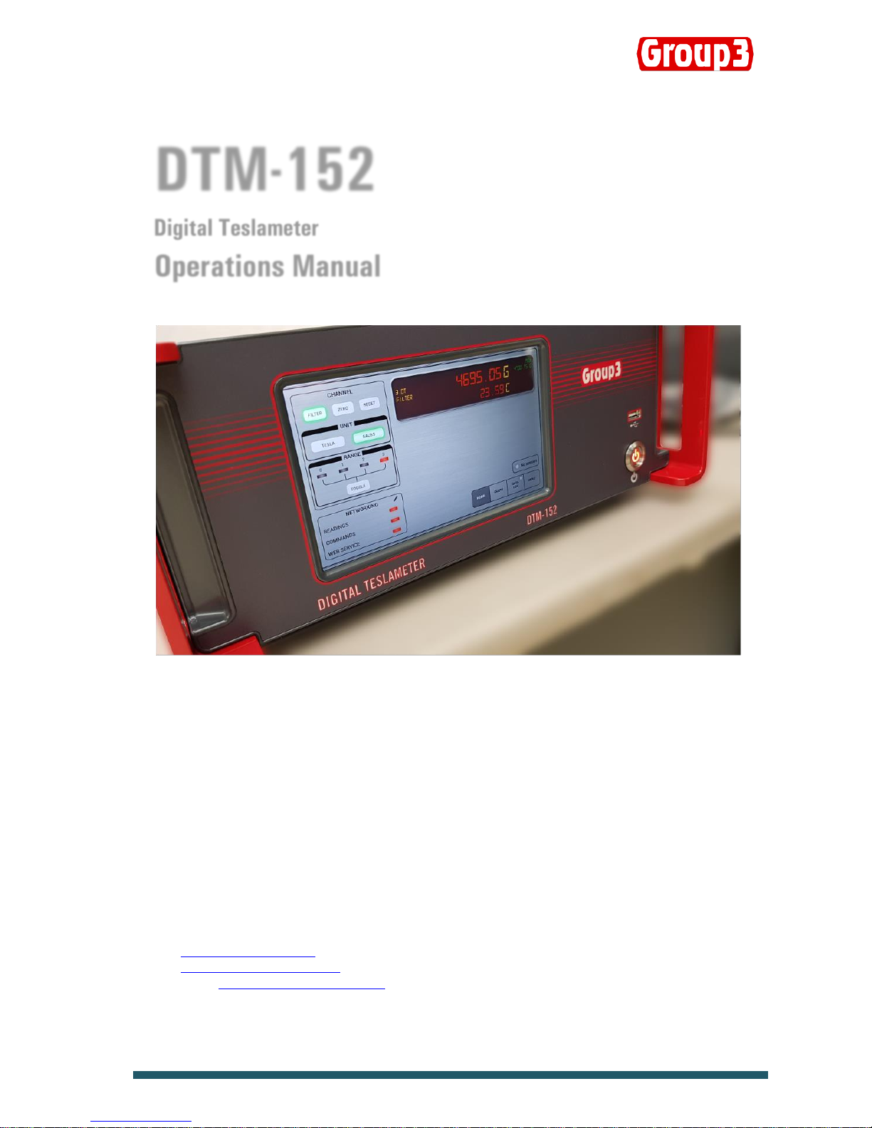
DTM-152
Digital Teslameter
Operations Manual
Group3 reserves the right to change the specifications at any time without notice. 01092018-D152
Group3 Technology Ltd.
2 Charann Place, Avondale
Auckland 1026 , New Zealand
PO Box 71-111, Rosebank, Auckland 1348, New Zealand
Phone: +64 9 828 3358
Fax: +64 9 828 3357
Email: sales@group3technology.com
Web: http://www.group3technology.com
Calibration/Repair: www.group3technology.com/service
Made in New Zealand

GROUP3 TECHNOLOGY LIMITED WWW.GROUP3TECHNOLOGY.COM
INTRODUCTION
Thank you for purchasing and using a Group3 Digital Teslameter. We hope you will join the many thousands of users worldwide who are
enthusiastic about our products.
The DTM-152 Digital Teslameter is the latest product of Group3 that boast a touch screen interface to operate the DTM. Instead of
mechanical switches and buttons that are still being used on the older versions to operate the unit, the DTM-152 display is touchscreenbased so setting the unit to user’s specification is quick and easy. The digital readout now shows not just the field reading but the
temperature of the sample at the same time.
Another new feature of the DTM-152 is its data logging capability where user can now do their data gathering on the DTM itself and saves
the output CSV file on to an external memory drive such as a USB drive or hard disk. This eliminates the need for a separate computer
terminal and software to do a data log of a particular session such as field mapping of a magnet.
Also, a new feature is the Graph function of the DTM-152. Users can now see the behavior of a particular session instead of just looking
at the field reading, the graphical display lets the user monitor visually if there are sudden or abrupt changes in the field over a period of
time. The time and field range are configurable depending on the user’s preferences.
Lastly, the DTM-152 now can be monitored and controlled over a network, thanks to the built –in Ethernet connectivity and our custombuilt LabView VI that comes with this unit. Applications such as synching the timing of a robot arm when mapping the field of a magnet
makes this an important and useful feature.
Group3 has been designing and building magnetic field measuring equipment since 1983. We are constantly upgrading our products and
support documentation. We welcome input from our customers, so if there are aspects of the instrument which you particularly like, or
which you would like to see improved, please contact your Group3 supplier (see back page for a complete list) or Group3 directly with your
suggestions to sales@group3technology.com .
The Group3 website, www.group3technology.com contains details of all our products.
This site is regularly updated, so check it from time to time to learn about recent developments.
GROUP3 TECHNOLOGY LIMITED WWW.GROUP3TECHNOLOGY.COM
DTM-152 Digital Teslameter Features
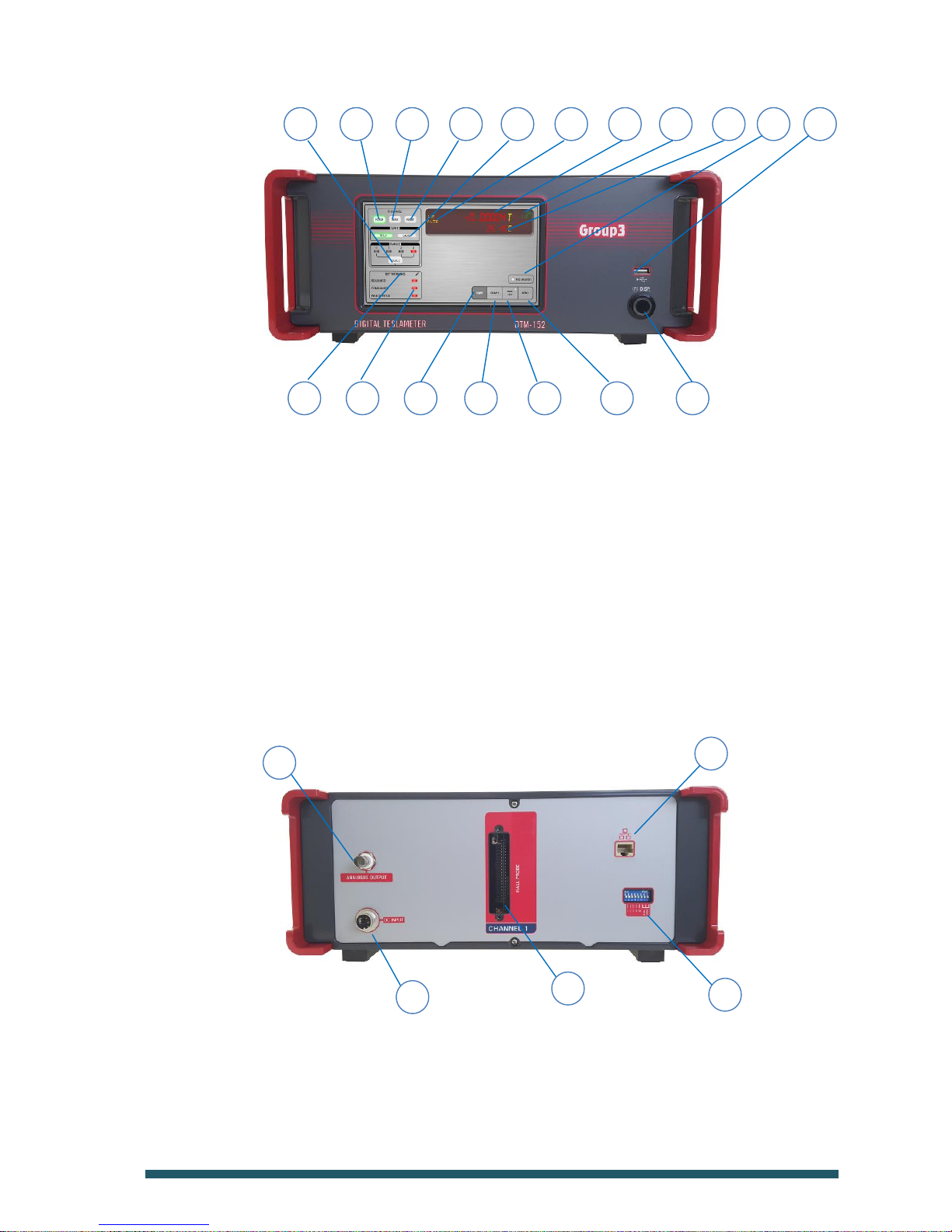
FRONT PANEL
1 Power Button Press to turn ON and OFF the unit
2 HOME Tab Touch to show the Main Readings screen
3 GRAPH Tab Touch to show and access Graph and configure controls
4 DATA LOG Tab Touch to do data logs and change Date/Time
5 MENU Tab Touch to access the DTM’s manual controls
6 NETWORKING Touch to access Ethernet networking controls
7 LED Buttons Touch to turn ON/OFF the Readings/Commands/Web Service controls
8 TOGGLE Button Touch to change the DTM range
9 FILTER Button Touch to turn ON/OFF the filter. Lights up a green color when ON.
10 ZERO Button Touch to set the reading to Zero. A green color indicates current unit.
11 RESET Button Touch to reset the unit.
12 UNIT Button Touch to choose either Gauss or Tesla.
13 Channel, Range & Filter Indicates the Channel/Axis, current range and filter status
14 Field Indicator Shows the measured magnetic field and temperature reading
15 Maximum Field Indicator Shows the maximum field measured
16 Temperature Indicator Shows the temperature of the sample as measured from the probe head
17 Session Indicator A GREEN light shows when an ongoing session. Otherwise, LED is in RED
18 USB Port Insert your USB Drive or memory stick to save data log files
REAR PANEL
1 DC Input Socket Attach the supplied DC Power supply and lock to secure the power plug.
2 Analogue Output Attach BNC connector to get analogue output
3 Hall Probe Socket Attach the probe plug into this socket and secure using 2 jackscrews
4 Ethernet Port Attach Ethernet jack (RJ45) to communicate with LabView interface
5 USB Port Additional USB port for memory drives
CONNECTIVITY
Ethernet Port Unit has a built-in Ethernet port for communication over network
1 5 4 3 2 7 6
14
13
12
11
10 9 8
15
16
17
18
5
4
2 1 3

GROUP3 TECHNOLOGY LIMITED WWW.GROUP3TECHNOLOGY.COM
SPECIFICATIONS OF DTM-152 SYSTEM
Specifications of DTM-152 with LPT-141 or MPT-141 Hall Probe.
Measurements field value and time-varying (ac) component of field
Field ranges 0.3 0.6 1.2 3.0 tesla full-scale,
3 6 12 30 kilogauss full-scale,
with polarity indication
maximum calibration field ±2.2 tesla, ±22 kilogauss
Resolution DC mode with digital filtering ON:
1 in 600,000 of bipolar span as shown on front panel display.
range display resolution
gauss tesla
0.3 tesla 0.001 0.0000001
0.6 tesla 0.01 0.000001
1.2 tesla 0.01 0.000001
3.0 tesla 0.01 0.000001
Resolution DC mode with digital filtering OFF, and AC mode:
1 in 120,000 of bipolar full-scale span in display:
range display resolution serial/GPIB resolution
gauss tesla gauss tesla
0.3 tesla 0.05 0.000005 0.001 0.0000001
0.6 tesla 0.1 0.00001 0.01 0.000001
1.2 tesla 0.2 0.00002 0.01 0.000001
3.0 tesla 0.5 0.00005 0.01 0.000001
20-bit digitizing of field reading.
Accuracy DTM-152 with LPT-141 or MPT-141 probe:
±0.01% of reading ±0.006% of full-scale max. at 25°C
Temperature DTM-152 with LPT-141 or MPT-141 probe:
Stability calibration: ±10 ppm of reading/°C max.
zero drift: ±(1 microtesla + 0.0003% of full-scale)/°C max.
add -3ppm/°C for each meter of probe cable
Time stability ±0.1% max. over 1 year
Measurement rate 10 measurements per second
Response time Full-scale change of displayed field reading settles to within
resolution in less than 0.3 second (filtering off - see below)
Peak hold mode Displays maximum field since mode entered or reset.
Peak hold is implemented digitally with zero sag or decay.
Display Touchscreen, soft key navigation, simulated 7-character, 7-segment alphanumeric display
Tabs HOME:
• Field and Temperature reading in simulated 7-segment display
• Field Unit in either GAUSS or TESLA indicated by GREEN backlight
• FILTER is set to ON by default as indicated by a GREEN backlight, press to turn OFF.
• Press RESET button to do a power cycle and reset the unit.
• Press ZERO button to zero any stray field.
• Maximum Field, Filter, Mode and Range status are displayed inside the readings display.

GROUP3 TECHNOLOGY LIMITED WWW.GROUP3TECHNOLOGY.COM
• SESSION indicator lights up GREEN when there is a session running. Graph can be zoomed in or out if a
session is in progress.
• Displays the number of Out of Range readings in that session
• Range indicator is lit in RED. Press the TOGGLE button to select the range.
• Networking – LAN port available. Communicates with any Windows PC using DHCP.
GRAPH:
• Graphical representation of field
• Field reading including maximum field
• Configuration button to set time frame, offsets and zeroing
• SESSION indicator lights up GREEN when there is a session running. Graph can be zoomed in or out if a
session is in progress.
• Displays the number of Out of Range readings in that session
DATA LOG:
• Set the sample number and sample rate
• Displays the memory capacity information when a USB memory stick / drive is inserted
• Display the Time/Date and is configurable by pressing the time/date text
• Multiple session is available
MENU:
• Master functions as well as other control features such as restting, zeroing, filtering, etc. are available
in this tab.
Analog outputs dc output - instantaneous field analog:
full-scale output: ±3V nominal
source impedance: 1000Ω
accuracy: ±10%
bandwidth: 3kHz at -3dB, rolloff 3-pole 60dB/decade
ac output - rectified analog of time-varying (ac) field:
frequency response: 8Hz to 3kHz at -3dB points
time-constant: 0.2 seconds
average responding, delivers rms value of sinusoidal field
full-scale output: 3V nominal
source impedance: 1000Ω
accuracy: ±12%
Memory backup user-entered data storage for 30 days with power off.
Power source
Model No. GSM36B12
Input: 100-240VAC, 50/60Hz, 0.9-0.45A
Output: 12V , 3A, 36W Max.max 15V, 0.35A rms
Power fuse on processor board: 1 amp anti-surge 5 x 20mm
Data Log Via USB, data log file saved in CSV format
Enclosure All metal, with tilt stand on bench models, mounting cheeks on rack
Dimensions 350 (L) x 320 (W) x 150 (H, including feet ) mm ,
Instrument Weight 5.8 kg,
Shipping Weight 12.5Kg (includes power pack, mounting cheeks and hard case)
Ambient field Maximum operating field for electronics package:
10 millitesla with single-range probe,
0.5 millitesla with multi-range probe.
Temperature range 0 to 50°C operating, absolute maximum temperature of probe 60°C

GROUP3 TECHNOLOGY LIMITED WWW.GROUP3TECHNOLOGY.COM
CONNECTING THE HALL PROBE
Before handling the probe, please read the following:
Group3 Hall probes are built to be as robust as possible for a small, precision device. However, it is most important that certain precautions
be taken when handling and installing probes so that they are not damaged or destroyed, and to preserve their accurate calibration.
Mount the probe head so there is no pressure which will tend to bend or depress its ceramic rear surface. If the probe head is clamped,
make sure the surface in contact with the ceramic is flat and covers the whole of the ceramic surface. Do not apply more force than is
required to hold the probe in place. Any strain on the ceramic will alter the probe's calibration, and excessive force will destroy the Hall
element inside. When the probe head is mounted, the cable should be clamped firmly nearby so it cannot be torn away from the probe head
if accidentally pulled. The flexible section adjacent to the probe head can be carefully folded to allow the cable to come away in
any direction but avoid repeated flexing of this section.
Keep the cable out of the way of foot traffic. Do not pinch the cable or drop sharp or heavy objects on it. A severed cable cannot be rejoined without altering the probe's performance and requires factory repair and re-calibration.
The DTM-152 must be used with a Group3 Hall probe. Probe models LPT-141, LPT-231, MPT-141, or MPT-231 are the most suitable for
use with the DTM-152. The probe may be one supplied with your teslameter, or it may have been obtained separately. In any case,
calibration is preserved when probes are exchanged between instruments.
The standard probe cable length is 2 meters. Probes with non-standard cable lengths up to 30 meters may be ordered from your Group3
supplier. The cable used for Group3 probes is shielded to reduce pickup of induced noise from external sources. Such noise may reduce the
accuracy of the instrument, cause malfunctioning, or in extreme circumstances even result in damage to the internal circuitry.
ANALOG OUTPUT
An analog output signal is available at the rear of the teslameter. This output is the Hall probe signal amplified to 3 volts full-scale and gives
an indication of the instantaneous field value from dc to 9kHz (-3dB), with a roll-off of 60dB/decade above 9 kHz. Field direction is indicated
by the output voltage polarity. There is a small zero offset (10 millivolts maximum), arising from the probe zero-field output and amplifier
offsets. The output impedance is 1000 ohm with a 1nF capacitor to common for noise filtering.
pin signal
1 ground
2 dc output
Analog Output Connector Pin Assignments
GROUNDING
All parts of the teslameter's metal case are connected together to form an integral electric shield around the circuitry inside. When the
probe connector is plugged into the teslameter and the retaining screws are tightened, the probe connector case and the teslameter case
are connected together and form an integral shield around the circuitry inside. The cable shield is added to the case shield and extends
protection from electrical interference almost up to the probe head.
Because there is an internal connection between teslameter circuit common and the probe connector case, when the probe connector is
engaged, and the retaining screws tightened the teslameter circuit common will be connected to the case. Do not make an additional
connection between circuit common and the case at any point. Such additional connection will form a ground loop and may introduce errors
in the measured field value.
The shielding provided with the above arrangement should be sufficient protection against EMI in most cases, especially when the probe
cable is shielded. Sometimes it may be found helpful to ground the teslameter case to a good electrical ground point. Connection can be
made to the case by inserting an appropriate lug or terminal under the head of one of the rear panel fixing screws.
 Loading...