

Group3 DTM-151 User Manual

DTM-151
DIGITAL TESLAMETER
with IEEE-488 GPIB Interface
USER’S MANUAL
For units supplied with software DTMS V6.0 & V7.0
20 July 2007
Group3 Technology Ltd., 2 Charann Place, Avondale, Auckland 1026. P.O. Box 71-111, Rosebank, Auckland 1348, New Zealand.
Phone: +64 9 828 3358 Fax: +64 9 828 3357 email: info@group3technology.com web: www.group3technology.com

82010180
Thank you for purchasing and using a Group3 digital teslameter. We hope you will join
the many hundreds of users worldwide who are enthusiastic about our products.
Group3 has been designing and building magnetic field measuring equipment since
1983. We are constantly upgrading our products and support documentation. We
welcome input from our customers, so if there are aspects of the instrument which you
particularly like, or which you would like to see improved, please contact your Group3
supplier (see back page for a complete list) or Group3 directly with your suggestions to
info@group3technology.com.
The Group3 website, www.group3technology.com contains details of all our products.
This site is regularly updated, so check it from time to time to learn about recent
developments.
Group3 Technology Ltd.
2 Charann Place, Avondale, Auckland 1026
PO Box 71-111, Rosebank, Auckland 1348, New Zealand.
Phone: +64 9 828 3358
Fax: +64 9 828 3357
Email: info@group3technology.com
Web: http://www.group3technology.com
Group3 Technology Ltd., 2 Charann Place, Avondale, Auckland 1026. P.O. Box 71-111, Rosebank, Auckland 1348, New Zealand.
Phone: +64 9 828 3358 Fax: +64 9 828 3357 email: info@group3technology.com web: www.group3technology.com

CONTENTS
1. General Description 1-1
2. Specifications of DTM-151 System 2-1
3. Setting Up
3.1 Introduction 3-1
3.2 Connecting the Hall Probe 3-1
3.3 Connecting the Power Source 3-2
3.4 GPIB Connection 3-4
3.5 Internal DIP Switch Settings 3-6
3.6 Analog Outputs 3-10
3.7 Grounding 3-11
3.8 Installing the Panel Mount Option 3-12
3.9 Installation Techniques for Electrically Noisy Environments 3-13
4. Operating Instructions
4.1 Zeroing 4-1
4.2 Installing the Probe 4-2
4.3 Reading the Field Value 4-3
4.4 Display Modes, Using the Front Panel Keys 4-4
4.5 Using the IEEE-488 GPIB Interface 4-7
4.6 Digital Filtering 4-20
4.7 Triggered Operation 4-21
5. Technical Diagrams
General Information 5-1
Display Board Schematic 5-2
Display Board Component Overlay 5-3
Display Board Parts List 5-3
Probe Plug Board Schematic 5-4
Probe Plug Board Component Overlay 5-5
Probe Plug Board Parts List 5-5
Processor Board Schematic 5-6
Processor Board Component Overlay 5-7
Processor Board Parts List 5-8
Analog Board Schematic 5-9,10
Analog Board Component Overlay 5-11
Analog Board Parts List 5-12,13
DTM-151 (GPIB) User's Manual Contents-1

LIST OF FIGURES
Fig. 1 Power Input Connections of the -L option 3-3
Fig. 2 IEEE-488 Standard Connector 3-5
Fig. 3 Location of Processor Board Switches 3-7
Fig. 4 Panel Cutout Dimensions 3-12
Fig. 5 Probe Dimensions 4-3
Fig. 6 A Typical IEEE-488 System 4-7
Display Board Schematic 5-2
Display Board Component Overlay 5-3
Display Board Parts List 5-3
Probe Plug Board Schematic 5-4
Probe Plug Board Component Overlay 5-5
Probe Plug Board Parts List 5-5
Processor Board Schematic 5-6
Processor Board Component Overlay 5-7
Processor Board Parts List 5-8
Analog Board Schematic 5-9,10
Analog Board Component Overlay 5-11
Analog Board Parts List 5-12,13
LIST OF TABLES
Table 1 GPIB Connector Pin Assignments 3-4
Table 2 DIP Switch Functions 3-7
Table 3 String Terminator Switch Settings 3-8
Table 4 Analog Output Connector Pin Assignments 3-10
Table 5 IEEE-488 Command Codes 4-10
Table 6 DTM-151-_G IEEE-488 Command Codes 4-14
Table 7 DTM-151-_G IEEE-488 Commands 4-15,16,17
Contents-2 DTM-151 (GPIB) User's Manual

1 GENERAL DESCRIPTION
The DTM-151-_G Digital Teslameters offer accurate, high resolution measurement of
magnetic flux densities, with direct digital readout in tesla or gauss, and IEEE-488 GPIB
interfacing for system applications. The instruments are light and compact, and the
probes are easy to use. The DTM-151 has been engineered to withstand the severe
electrical interference produced by high voltage discharge.
This description includes features of the serial communications option which is an
alternative to the IEEE-488 option. If your teslameter is the serial version, refer to the
DTM-151-_S User's Manual.
FEATURES
Measures magnetic fields over four ranges up to 3 tesla with polarity indication;
resolution up to 1 part in 600,000.
Used with special miniature Hall probe - easy to attach to magnet pole or other
hardware. Probe holders are available as optional accessories.
Accuracy and temperature specifications include total system performance, probe and
instrument. This is the only meaningful indication of measurement accuracy.
Probe is calibrated, with field and temperature characteristics stored in memory chip
contained in cable plug.
Basic accuracy 0.01% of reading + 0.006% of full scale.
Microprocessor reads probe calibration data stored in probe connector and computes
corrected field reading.
Temperature coefficient 10ppm/°C overall achieved usin g temperature sensor in probe.
Microprocessor calculates corrected field reading.
Accuracy is verified against nuclear magnetic resonance (NMR) standard.
Probe calibration is verified at many field points, and a printed calibration table is
supplied with every probe.
AC mode measures and displays time-varying fields between 8 Hz and 3000 Hz.
Front panel keys set the display to read the desired field range, to read the peak value
of the field using the peak hold function, to show the ac field component, and to display
the probe temperature.
Peak hold is implemented digitally, has zero sag.
DTM-151 (GPIB) User’s Manual 1-1

Digital filtering of the displayed field reading suppresses short-term fluctuations. The
filtering characteristic is non-linear; small field variations within a narrow window
centered on the currently displayed value are filtered; large field changes are displayed
immediately. Filter window and time-constant may be changed by remote command.
Filtering is controlled by an internal switch.
Two digital communication options: either serial (RS-232C and fiber optic)
or IEEE-488 General Purpose Interface Bus.
With the serial option, a single teslameter may be connected to standard RS-232C
equipment, or up to 31 units may be interconnected on a Group3 Communication Loop
(G3CL) and driven from computer or terminal.
Fiber optic ports duplicate functions of RS-232C signals, for electrical noise immunity
and voltage isolation. Fiber optic links may be up to 60 meters in length, using
Hewlett-Packard HFBR-3500 series fiber optic cables. Use a Group3 fiber optic repeater
to extend communication distance.
The IEEE-488 option fully supports all relevant GPIB functions and commands, including
full talker-listener capability, serial and parallel polling, service request, and talker-only.
ASCII control commands are accepted to modify the output data format, to change the
rate of data transmission or to request transmission of a single field reading. Other
commands set scaling and offset, select the field range, select ac and peak hold
functions, turn on and off digital filtering and modify the filter characteristics. System
status may be determined remotely.
The system can be operated in triggered mode where field measurements by one or
more teslameters are triggered in synchronism with each other by external command.
Internal switches select serial data format and baud rate, device address, string
terminators, filtering, field units in gauss or tesla, data format, service request action,
EOI action, and perform system reset.
Two analog outputs are available: instantaneous field value (0 to 3 kHz), rectified
time-varying (ac) component of field, (8 Hz to 3 kHz).
All model variations are available without display and keys for true 'black box' magneticfield-to-computer interfacing.
A panel mount model with display is available.
1-2 DTM-151 (GPIB) User’s Manual

2 SPECIFICATIONS OF DTM-151 SYSTEM
Specifications include LPT-141 or MPT-141 Hall Probe.
Measurements field value and time-varying (ac) component of field
Field ranges 0.3 0.6 1.2 3.0 tesla full-scale,
3 6 12 30 kilogauss full-scale,
with polarity indication
maximum calibration field ±2.2 tesla, ±22 kilogauss
Resolution DC mode with digital filtering ON:
1 in 600,000 of bipolar span as shown on front panel display.
range display resolution serial/GPIB resolution
gauss tesla gauss tesla
0.3 tesla 0.01 0.000001 0.001 0.0000001
0.6 tesla 0.02 0.000002 0.01 0.000001
1.2 tesla 0.04 0.000004 0.01 0.000001
3.0 tesla 0.1 0.00001 0.01 0.000001
Resolution DC mode with digital filtering OFF, and AC mode:
1 in 120,000 of bipolar full-scale span in display:
range display resolution serial/GPIB resolution
gauss tesla gauss tesla
0.3 tesla 0.05 0.000005 0.001 0.0000001
0.6 tesla 0.1 0.00001 0.01 0.000001
1.2 tesla 0.2 0.00002 0.01 0.000001
3.0 tesla 0.5 0.00005 0.01 0.000001
20-bit digitizing of field reading.
Accuracy DTM-151 with LPT-141 or MPT-141 probe:
±0.01% of reading ±0.006% of full-scale max. at 25°C
Temperature DTM-151 with LPT-141 or MPT-141 probe:
Stability calibration: ±10 ppm of reading/°C max.
zero drift: ±(1 microtesla + 0.0003% of full-scale)/°C max.
add -3ppm/°C for each meter of probe cable
Time stability ±0.1% max. over 1 year
DTM-151 (GPIB) User’s Manual 2-1

Measurement rate 10 measurements per second
Response time Full-scale change of displayed field reading settles to within
resolution in less than 0.3 second (filtering off - see below)
Peak hold mode Displays maximum field since mode entered or reset.
Peak hold is implemented digitally with zero sag or decay.
AC mode Displays time-varying (ac) component of field;
frequency response: 8 Hz to 3 kHz at -3dB points.
response time-constant: 0.2 seconds.
average responding,
reads rms value of sinusoidally-varying field.
reading is not linearity or temperature corrected.
Display 7-character 7-segment alphanumeric display.
Indicators 8 back-lit legends for:
0.3 0.6 1.2 3.0 tesla range selected,
peak hold mode on, digital filtering on, tesla/gauss field units.
Display modes magnetic field, peak hold field, ac field, peak ac field
Digital filtering field value filtering smoothes out small fluctuations in the reading;
large, rapid field changes are not filtered;
internally switch selected.
Keys 2 keys for range selection, access to display modes,
zeroing field display, peak hold reset.
Digital interfacing serial option: RS-232C and fiber optic.
parallel option: IEEE-488 General Purpose Interface Bus.
Digital data format ASCII input commands and output responses.
Commands requests for field values,
setting and inspection of display and control modes,
field measurement triggering, entry of numerical values,
setting units, output data format, and filter characteristics,
test commands.
Output responses field value in tesla or gauss followed by optional T or G
and string terminator(s), system status,
numerical data requested by commands, messages.
2-2 DTM-151 (GPIB) User’s Manual

Serial bit rate 16 rates, switch selected, 50, 110, 134.5, 150, 200, 300, 600,
900, 1050, 1200, 1800, 2000, 2400, 4800, 9600, 19200 baud.
System orientation Group3 Communication Loop (G3CL) using serial ports,
simple loop for 31 devices, no multiplexer required;
GPIB with IEEE-488 option.
Fiber optic cable Hewlett-Packard HFBR-3500, 60 meters max.
Fiber optic repeater available for extended communications.
On-board switches serial baud bit rate selection, load defaults, device address,
filtering, string terminators, data format,
service request enable, EOI enable.
Analog outputs dc output - instantaneous field analog:
full-scale output: ±3V nominal
source impedance: 1000Ω
accuracy: ±10%
bandwidth: 3kHz at -3dB, rolloff 3-pole 60dB/decade
ac output - rectified analog of time-varying (ac) field:
frequency response: 8Hz to 3kHz at -3dB points
time-constant: 0.2 seconds
average responding, delivers rms value of sinusoidal field
full-scale output: 3V nominal
source impedance: 1000Ω
accuracy: ±12%
IEEE-488 functions SH1 source handshake capability
AH1 acceptor handshake capability
T5 talker (basic talker, serial poll, talk-only mode,
unaddressed to talk if addressed to listen)
TE0 no address extension talker capability
L4 listener
(basic listener, unaddressed to listen if addressed to talk)
LE0 no address extension listener capability
SR1 service request capability
RL0 no remote local capability
PP1 parallel poll capability (configured by controller)
DC1 device clear capability
DT1 device trigger capability
C0 no controller capability
GPIB connector standard Amphenol 57-20240 with metric standoffs
DTM-151 (GPIB) User’s Manual 2-3

Memory back-up user-entered data storage for 30 days with power off.
Power source ac: min 8V at 0.7Arms, max 15V at 0.4Arms
dc: min 9V at 0.5A, max 19V at 0.25A
ac line input plugpack supplied.
Power fuse on processor board: 1 amp antisurge 5 x 20mm
To obtain maximum spark protection, use PS12D7 power supply
and ferrite kit 11000036. See section 3.9.
L option: 115/208/230 V ac power input.
Enclosure aluminium, 217 x 125 x 50 mm, textured finish,
light tan colour, tilt stand fitted to bench models.
Ambient field Maximum operating field for instrument:
10 millitesla with single-range probe,
0.5 millitesla with multi-range probe.
Temperature range 0 to 50°C operating,
absolute maximum temperature of probe 60°C.
Instrument weight 1.2 kg, shipping weight 2.5 kg.
Probes LPT series, transverse types,
sensitive area 4 x 1.6mm,
probe head size:
LPT-141 and LPT-231: 14 x 14 x 2.5 mm
MPT series, miniature transverse types,
sensitive area 1.0 x 0.5mm,
probe head size:
MPT-132 MPT-230 MPT-141 MPT-231: 14 x 5 x 2 mm
Standard cable length: 2 meters.
Special cable lengths to 30 meters.
Probe cable is shielded.
2-4 DTM-151 (GPIB) User’s Manual

ORDER CODES
Basic teslameters,
capable of four measurement ranges 0.3, 0.6, 1.2, 3.0 tesla full scale,
support all LPT and MPT series probes, plugpack supplied except for option -L.
DTM-151 (supports LPT-141, LPT-231, MPT-141, MPT-231 probes)
Options
Bench style instrument with display: add suffix -D |
Panel-mount version: add suffix -P | one of these options
Without display, plugpack powered: add suffix -N | must be specified
Without display, line voltage power: add suffix -L |
IEEE-488 GPIB capability: add suffix G | must select
Serial data input/output, RS-232C & fiber optic: add suffix S | one option
Example: DTM-151-DG
Probes
Four ranges, standard 2 meter shielded cable
LPT-141-2s | standard sensitivity LPT-231-2s | high sensitivity
MPT-141-2s | probes MPT-231-2s | probes
Single range probes: add range suffix -03, -06, -12, -30.
Special probe cable lengths: change length suffix to -Xs,
where X is the desired cable length in meters, 30 max.
Example: LPT-141-10s for 10 meter cable
Accessories
fiber optic cable fitted with connectors, 60 meter length maximum.
probe holders.
fiber optic repeater, bidirectional, model FOR-2PP.
fiber optic to RS-232C adaptor, model FTR.
serial/GPIB adaptor, model COM-488.
digital display for remote control & readout of field values, model DPM.
rack panels, 3.5 inches high (2U), for rack mounting 1, 2, or 3 DTMs or DPMs.
ferrite kit 11000036 for spark protection.
power supply PS12D7 for spark protection.
DTM-151 (GPIB) User’s Manual 2-5

2-6 DTM-151 (GPIB) User’s Manual

3 SETTING UP
3.1 INTRODUCTION
This manual provides operating instructions for all members of the DTM-151 family of
digital teslameters with IEEE-488 interfacing, and their companion LPT-141, LPT-231,
MPT-141, and MPT-231 series Hall probes. For a summary of all current members of
the product family, see page 2-5. These instructions are written for a teslameter with
front panel display and keys, DTM-151-DG/PG. Users of teslameters without display and
keys should ignore sections of this manual referring to these features. All other aspects
of operation are identical. Before using your teslameter for the first time, please read
through sections 3.2, 3.3, 4.1, 4.2, and 4.3 of this manual. This will give a quick
introduction to basic operation of the instrument. If you have a teslameter without
display, DTM-151-NG/LG, also read sections 3.4, 3.5, and 4.5. If you have the
panel-mount version, DTM-151-PG, mounting instructions are to be found in section 3.8.
For help regarding operation in electrically noisy areas, see section 3.9.
3.2 CONNECTING THE HALL PROBE
Before handling the probe, please read the following.
Group3 Hall probes are built to be as robust as possible for a small, precision device.
However, it is most important that certain precautions be taken when handling and
installing probes so that they are not damaged or destroyed, and to preserve their
accurate calibration.
Mount the probe head so there is no pressure which will tend to bend or depress its
ceramic rear surface. If the probe head is clamped, make sure the surface in contact
with the ceramic is flat and covers the whole of the ceramic surface. Do not apply more
force than is required to hold the probe in place. Any strain on the ceramic will alter the
probe's calibration, and excessive force will destroy the Hall element inside.
When the probe head is mounted, the cable should be clamped firmly nearby so it
cannot be torn away from the probe head if accidentally pulled. The flexible section
adjacent to the probe head can be carefully folded to allow the cable to come away in
any direction, but avoid repeated flexing of this section.
Keep the cable out of the way of foot traffic. Do not pinch the cable, or drop sharp or
heavy objects on it. A severed cable cannot be re-joined without altering the probe's
performance, and requires factory repair and re-calibration.
Your DTM must be used with a Group3 Hall probe. The probe may be one supplied with
your teslameter, or it may have been obtained separately. In any case, calibration is
preserved when probes are exchanged between instruments. In order to obtain specified
performance, the DTM-151 should be used only with a -141 and -231 series probes.
DTM-151 (GPIB) User’s Manual 3-1

The standard probe cable length is 2 meters. Probes with non-standard cable lengths up
to 30 meters may be ordered from your Group3 supplier. The cable used for Group3
probes is shielded to reduce pickup of induced noise from external sources. Such noise
may reduce the accuracy of the instrument, cause malfunctioning, or in extreme
circumstances even result in damage to the internal circuitry. See section 3.9.
With the DTM unpowered, plug the probe connector into the instrument. The pin side of
the plug is inserted into the large opening in the rear of the DTM, with the plug's label
uppermost when the instrument is standing right way up. It is easy to find the correct
mating position for the plug, and then push it fully home, but if any difficulty is
experienced at first, remove the DTM's top cover by loosening the central screw and
lifting the cover off. Now it is possible to see when the plug is centrally located and its
overhang slides over the card-edge receptacle, ensuring that its pins engage correctly.
Tighten the connector retaining screws finger tight. Do not leave these screws loose as
they form part of the shielding system around the teslameter. The teslameter should
always be used with both covers attached.
Always disconnect power from the teslameter before connecting or disconnecting the
probe. If the probe connector is inserted or withdrawn with power on, data stored in
memory may be corrupted, leading to erroneous field readings. If this happens, the
defaults switch S2-8 should be switched ON then OFF while power is applied. See Fig. 3
and Table 1.
When no probe is connected to the DTM, the display reads noProbE.
3.3 CONNECTING THE POWER SOURCE
All teslameter versions, except for the L option, are supplied with a plug-pack. Connect
the plug-pack to a convenient ac power source, first checking the voltage marked on the
plug-pack, and insert the cable connector into the power receptacle on the DTM rear
panel.
Instead of the plug-pack, the unit can be powered by any convenient source of ac or dc
(either polarity), 9 to 15 volts, capable of supplying 0.7A rms ac or 0.5A dc. The cable
connector required for power connection to the DTM is a standard coaxial plugpack
connector with 2.1mm centre hole and is generally available from electronics suppliers.
For extra immunity to damage and operational disturbance caused by serious high
voltage sparking near the teslameter, the use of the Group3 model PS12D7 off-line
switch-mode power supply and the Group3 ferrite kit part no. 11000036 is
recommended. These accessories will greatly reduce the amount of electrical transient
energy entering the teslameter. The ferrite kit includes a suppressor which fits to the
probe cable near the point of entry to the teslameter to reduce the effects of transients
picked up on the probe cable. For a full discussion of techniques to promote trouble free
operation in electrically noisy environments, see section 3.9 of this manual.
3-2 DTM-151 (GPIB) User’s Manual

Powering the L option teslameter -
GND
PWR
LINK
PWR
LINK
GND
PWR
LINK
LINK
GND
PWR
CASE
PWR
PWR
The L option will accept power input from the ac power line.
Access to the power input terminals of the L option is obtained by taking off the orange
cover; remove the 3 fixing screws to release the cover.
Use 3-conductor power cord. For safety from electrical shock it is essential to provide a
reliable ground connection to the DTM case. Make sure the ground wire is connected as
shown in Fig. 1. Strip about 60 mm (2.5 in) of outer jacket from the cord, and strip 5 mm
(3/16 inch) of insulation from the 3 wires. Pass the cord through the grommetted hole in
the cover. Loosen the screw securing the cable clamp and pass the cord through the
clamp. Tighten the clamp on the outer jacket. Terminate the wires and fit links according
to the supply voltage as set out in Fig. 1 below. Replace the orange cover, making sure
that wires are not pinched in the process. For safety reasons, do not operate the unit
with the cover off.
Note that input power protection is provided by a thermal fuse wound into the power
transformer. This fuse will open in the event of transformer overheating rather than on
excess current. The power input must be connected as shown to include the thermal
fuse in the circuit correctly. If a fault causes transformer overheating and subsequently
the fuse opens, the transformer must be replaced with the genuine Group3 part.
1
2
3
4
5
6
7
1
2
3
4
5
6
7
1
2
3
4
5
6
7
115V 208V 230V
Fig. 1. Power Input Connections of the -L option
If desired, the wiring may be protected by installing an external fuse in the ac power
feed. Suggested fuse ratings are 200 mA for 115 volts, or 100 mA for 208 and 230 volt
operation.
When the unit is first powered up, the display shows Group3 for 2 seconds before field
measurements appear. If the Hall probe is not plugged in, the field reading display is
replaced with noProbE.
DTM-151 (GPIB) User’s Manual 3-3

3.4 GPIB CONNECTION
Connection to the GPIB connector on the rear of the DTM is made using cables as
specified in the IEEE-488-1978 standard document. Briefly, the cable has 24 conductors
with an outer shield. The connectors at each end are 24-way Amphenol 57 series or
similar with piggyback receptacles to allow daisy-chaining in multiple device systems.
The connectors are secured in the receptacles by a pair of captive locking screws with
metric threads. The total length of cable allowed in a system is 2 meters for each device
on the bus, or 20 meters maximum. A system may be composed of up to 15 devices.
Table 1 is a listing of the GPIB connector pin assignments. Fig. 2 shows the connector
pin location and signal names as viewed on the teslameter rear panel.
pin symbol description
1 DIO1 Data Input Output line 1
2 DIO2 Data Input Output line 2
3 DIO3 Data Input Output line 3
4 DIO4 Data Input Output line 4
5 EOI End Or Identify
6 DAV Data Valid
7 NRFD Not Ready For Data
8 NDAC Not Data Accepted
9 IFC Interface Clear
10 SRQ Service Request
11 ATN Attention
12 SHIELD Cable shield - connects to teslameter case
13 DIO5 Data Input Output line 5
14 DIO6 Data Input Output line 6
15 DIO7 Data Input Output line 7
16 DIO8 Data Input Output line 8
17 REN Remote Enable - not used in teslameter
18 GND 6 Ground wire of twisted pair with DAV
19 GND 7 Ground wire of twisted pair with NRFD
20 GND 8 Ground wire of twisted pair with NDAC
21 GND 9 Ground wire of twisted pair with IFC
22 GND 10 Ground wire of twisted pair with SRQ
23 GND 11 Ground wire of twisted pair with ATN
24 GND Teslameter logic ground
Table 1. GPIB Connector Pin Assignments
3-4 DTM-151 (GPIB) User’s Manual
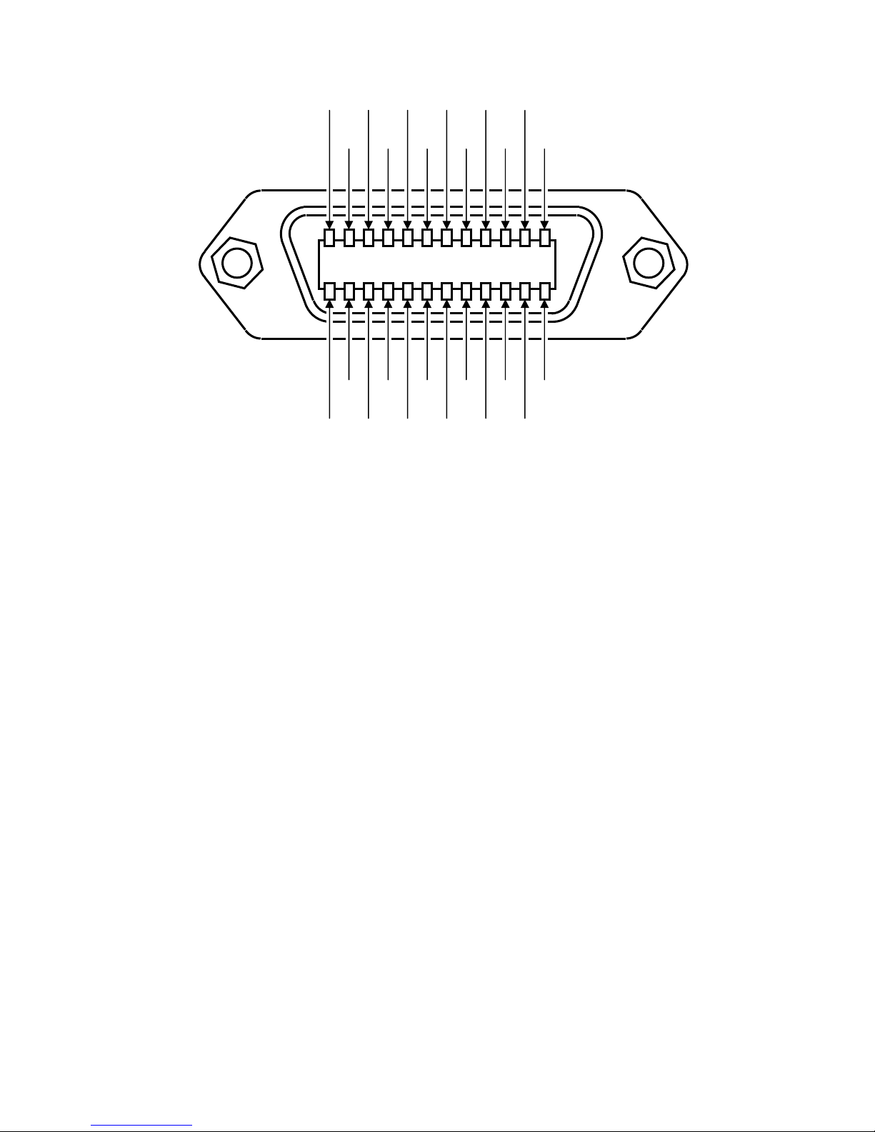
12 7 11 10 9 8 6 5 4 2 3 1
24 19 23 22 21 20 18 17 16 14 15 13
SHIELD SRQ NDAC DAV DI04 DI02
ATN IFC NRFD EOI DI03 DI01
LOGIC
GND
GND
11
GND 9 GND
GND
10
7
GND 8 GND
6
REN DI07 DI05
DI08 DI06
Fig. 2. IEEE-488 Standard Connector
DTM-151 (GPIB) User’s Manual 3-5
 Loading...