

Page 1

DSP SERIES
DIGITAL SIGNAL
PROCESSOR
GZDSP 4-8XII
Owner´s manual
• Digital signal processor (DSP) – 2x Analog Devices SigmaDSP
• 4-channel line input (RCA)
• 4-channel high-level input (with auto-on function)
• 8-channel line output (RCA)
• Realtime setup of all functions (via PC or APP*)
• Simple handling, one-page graphical user interface (Windows
• Parametric equalizer for each channel (8x 10 bands)
• Time alignment (0-8 ms / 0-272 cm / 0-107”) for each channel
• Adjustable crossover (HPF / LPF / BPF from 20 Hz to 20 kHz)
• Selectable crossover slope (6 to 24 dB/oct)
• 3 filter characteristics (Butterworth/Bessel/Linkwitz-Riley)
• Selectable phase shift for each channel (0˚ or 180°)
• Memory for 6 user presets (selectable via remote control, PC or APP*)
• Wired remote control (available separately)
• Heatsink dimensions (w x l x h): 6.65” x 4.57” x 1.06”
*with optionally available USB BT adapter connected
App control and wireless music streaming
To use your mobile device controlling the unit and changing the adjustments, please install the
GROUND ZERO GZDSP 4-8XII control app on your device (And roid / iOS) and connect the separately
available music streaming interface. Check the web page for further information and to download the
app´s owner´s manual.
Feature list
®
compatible)
Page 2
GROUND ZERO GZDSP 4-8XII
DSP SERIES
Package content
2
General installation note
3
Connections
3
Harness connector pinout
4
PC software and USB connection
4
Graphical user interface (GUI)
5-6
Memory functions
6
Options dropdown menu
7
Technical specifications
7
Terms of warranty
7
Error diagnosis
8
-2-
The GZDSP 4-8XII is a digital signal processor increasing the sound quality of the vehicle´s audio equipment, based
on two 28-bit DSP chipsets in combination with four 24-bit AD and eight separate DA converters. Due to its universal
summing function combining up to 4 high-level channels and its 8x 10-band equalizing, the GZDSP 4-8XII can be
integrated into most OEM sound systems.
Product description
Table of contents
Package content
• 1 x GZDSP 4-8XII
• 1 x USB cable (A to B connector)
• 1 x Power supply and high-level input harness
• 1 x CD-ROM (software & drivers) compatible with
Microsoft Windows
®
XP SP3, Vista, 7, 8, 8.1 and 10
• 1 x Owner’s manual (German/English)
• 1 x Fastening kit Separately available
Available separately
• GZDSP BTS 4-8XII wireless music streaming USB adapter
(required for app control)
• GZDSP REM 4-8XII wired remote control
GROUND ZERO products are engineered in Germany
GROUND ZERO - international sponsor of
Page 3
DSP SERIES
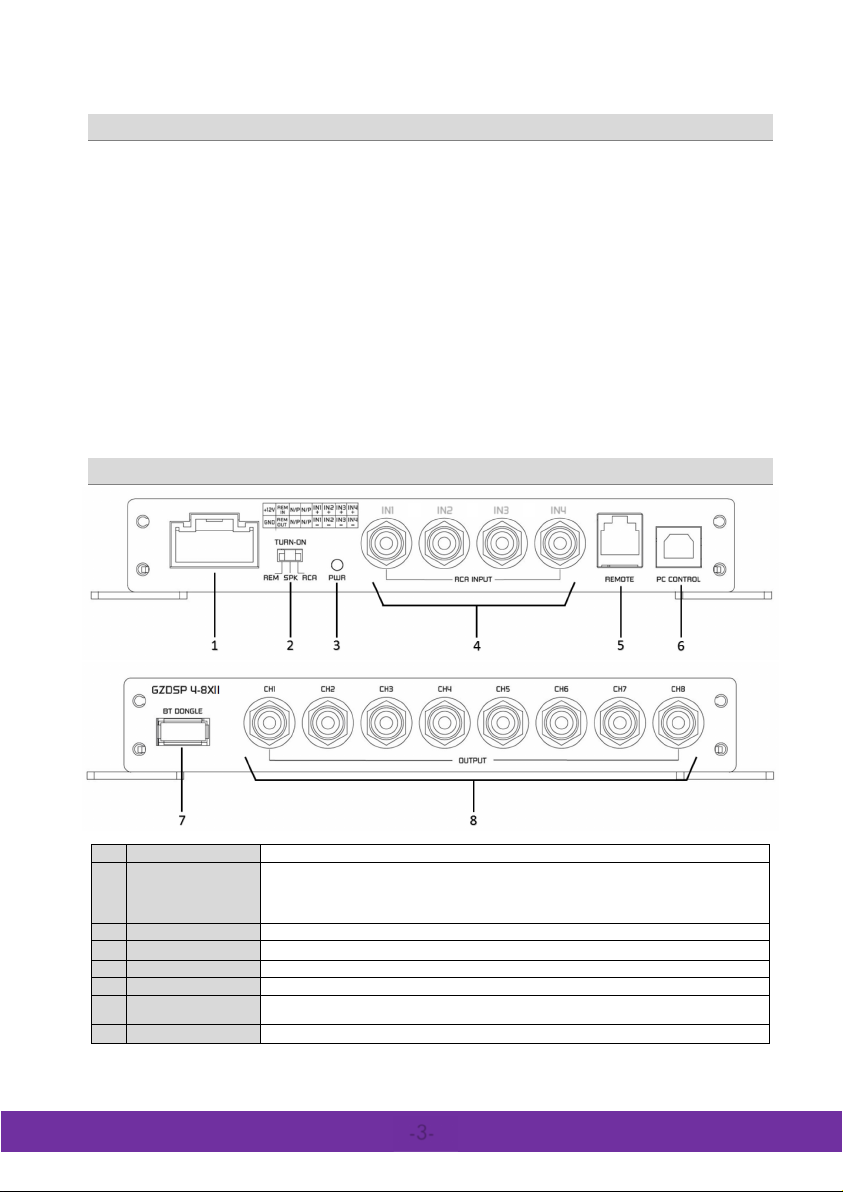
1
Harness connecti on
To connect the power and s peaker input harness (check the pi nout on th e next p age).
2
TURN-ON swi tch
This unit offers automatic turn-on. Using the feature , it´s unnecessary to connect a remote wire.
Caution: The high-level input and the line input cannot be used simultaneously. This may
lead to malfunction and cause serious damage to the DSP unit.
3
Power indication
Indicating the operation status
4
Line input (RCA)
To connect the head -unit´s pre-amplified line output audio signal (RCA)
5
Remote control
To connect the sup plied wired remote contro l
6
USB port
To connect the supplied USB cable to a compatible Windows PC´s USB port
7
Port for optional
BT adapter
To connect the optionally availa ble interface for wireless music streaming. The interface is
required to control the unit and adjust the settings using a mobile device (app), as well.
8
Line output (RCA)
To connect one or more amplifiers using RCA signal cables
IN1
• As a p recaution, it is recommend ed to di sconnect the vehicl es battery before m ounting the am plifier. ( Note: For new vehi cles,
disconnecting the battery might cause various errors in your vehicle´s electric system that can be cleared only by authorized
service partner s of your v ehicle´s manufa cturer! P lease a sk your s ervice p artner fi rst before disco nnecting the battery!)
• The power supply wire (+12 V) has to be protected within max. 20 cm / 8” by a main fuse holder with a fuse value matching
the recommendation for your amplifier
(Note: I f there is more tha n one amplifier connected using this power wire, the main fuse value must b e equal to the sum of the
recommended fuses of all co nnected devices. However, make s ure the d iameter of your po wer wire will be sufficient for the
required current!)
• If necessary, replace a defective fuse by a fuse with identical quality and value
• Never drill a hole to the vehicle´s gas tank or brake lines, to wirings or any other important vehicle parts!
• Never pass wires over sharp edges or vehicle parts to avoid any kind of damage
• Keep the wiring away from the antenna and electronic devices contributing to radio reception
• Lay the power supply wiring always separated from speaker wiring to avoid disturbance
• The amplifier contains a temperature protection circuit that turns the device off in case of overh eating. After a c ertain cooling
time, it will turn on automatically. To avoid heat build-up, sufficient air supply for cooling must be provided. Never cover the
surface of th e amp lifier´ s heats ink entir ely
• The DSP unit should NEVER be mounted onto a vibrating part or surface such as a subwoofer enclosure. This might lead to
malfunction due to loosened electrical parts inside the amplifier.
• Some amplifiers offer a high-level input option, however if a pre-amplified output (RCA) is available (at the head unit), it is
strong ly recommended to make use o f them.
General installation note
GROUND ZERO GZDSP 4-8XII
Connections
IN2
IN3
IN4
Set the switch to the RCA position for line input or SPK position for the high-level input.
-3-
Page 4
GROUND ZERO GZDSP 4-8XII
DSP SERIES
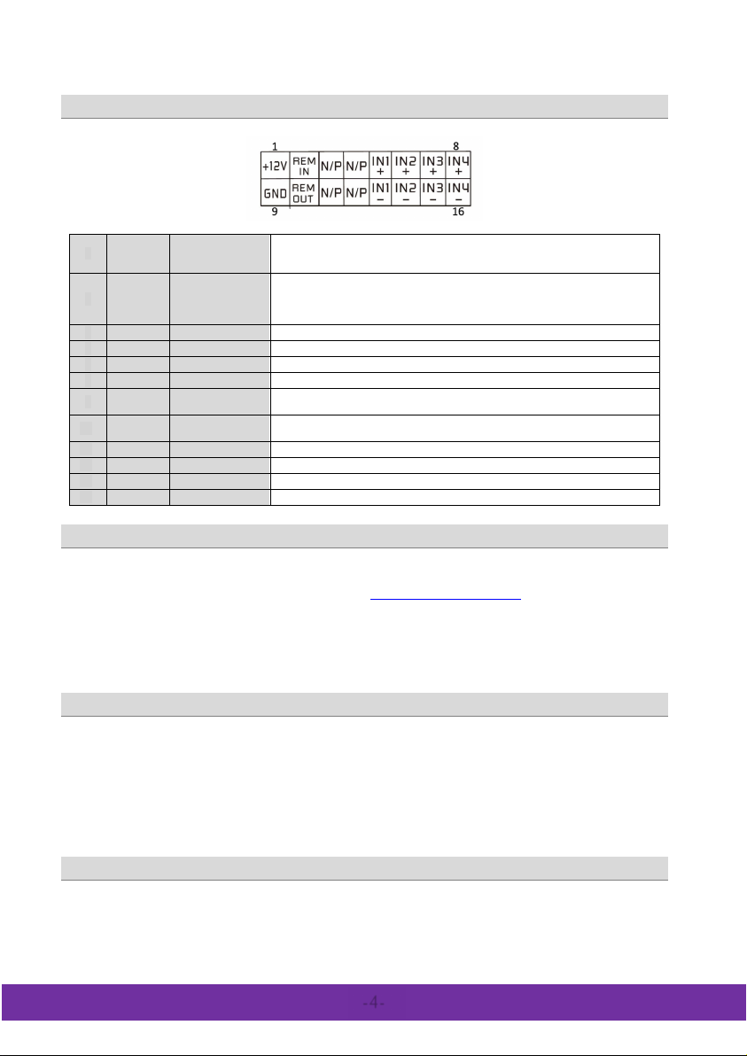
1
Yellow
+ 12 V
Power supply
Connect th e unit to the pos itive p ole (+) of the vehi cle´s battery. Use adequate
A fuse) not further than 30 cm / 1 2” away from the t erminal of the battery
2
Blue
Remote input
Using the line in put (RCA ), a remote wire ca n be connected to turn on the DSP unit.
superfluous.
5
White
Channel 1 (+)
To connect the le ft front speaker output (+)
6
Grey
Channel 2 (+)
To connect the rig ht front speaker output (+)
7
Green
Channel 3 (+)
To connect the le ft rear speaker output (+)
8
Purple
Channel 4 (+)
To connect the rig ht rear speaker output (+)
9
Black
Ground ( GND)
Connect the unit to a suitable ground terminal. The ground wire should be as short
as possible and be mounted to an unvarnished metal part
10
Blue/
White
Remote ou tput
To be used with additional system equipment like amplifiers to turn on together with
the DSP unit. The current is limited to 500 mA max.
13
White/bl
Channel 1 (-)
14
Grey/bl
Channel 2 (-)
15
Green/bl
Channel 3 (-)
16
Purple/bl
Channel 4 (-)
cable s ide vi ew
Harness connector pinout
wiring gauge (not less than 1.0 mm² / 17 AWG) with an additional fuse holder (2
In this case, set the TURN-ON switch to the REM position. Setting th e switch to the
RCA or SPK position activa tes the auto-on function, in that case a remote wire is
To connect the le ft front speaker output (-)
To connect the right front speaker output (-)
To connect the le ft rear speaker output (-)
The PC software is compatible* to Windows™ XP (SP3) operating systems (or later). One USB port and 25 MB free memory
space is required for the installation. The files are located on the included CD-ROM. If there is no CD driv e available, t he
software can be downloaded from the Ground Zero web page:
* compatible operating systems: Microsoft Windows® XP SP3 / Vista / 7 / 8 / 8.1 / 10
PC requirements: min. 1.5 GHz processor with 1 GB main memory (RAM) and graphic cards
with a resolution of 1024x600 pixels or more
USB connection: We don´t recommend using any passive extension cable together with th e includ ed USB wir e, as the proper
function can´t be ensured.
DSP setting: The unit must be connected to a PC with the DSP software installed using the included USB wire. To adjust any
setting the unit must be in operation mode. Click the program icon on the desktop or select the program from the softwa re
list to start. The starting window appears.
Windows® user account control (UAC): In case the PC oper ating system is set to restrict ed security clear ance reg arding
software with unknown source or without digital signature a window will appear each time at the program is starting. Please
confirm with >Yes< (language depends on your local setting) to run the program
In order to use the software, a communication to the PC must be esta blished. Therefore, an unused USB port is required. During
the connection of the USB cable the syst em will assign automatically a USB port.
Run the setup.exe file. The installation wizar d will guide through the installation process.
Note: We strict ly recommend using the latest DSP software available from the web page.
To connect the right rea r speaker output (-)
PC software installation
www.ground-zero-audio.com
USB connection
USB port
-4-
Page 5
DSP SERIES
GROUND ZERO GZDSP 4-8XII
Graphical user interface (GUI)
-5-
Page 6
GROUND ZERO GZDSP 4-8XII
DSP SERIES
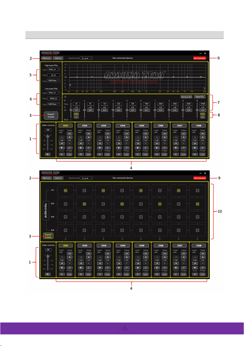
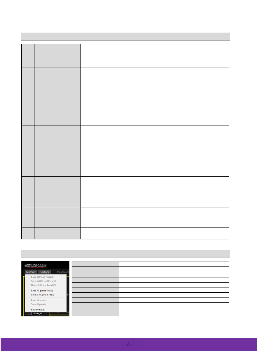
1
Main lev el
2
Memory / Options
dropdown menu
Tap the button to op en the dropdown menu.
3
Expert mode
Switch to the channel matrix.
Further information about the dropdown menu is to be found at section 10
4
Channel
Channel: Select the required channel tapping the according button
Level:
Mute:
Input:
Delay:
Phas e:
Link:
5
High pass filter
Type: Select the filter cha racteristic from the dropd own menu
Freq:
Slope:
Note: The fil ter can be adjus ted using the PC mouse at the frequen cy cha rt directly
6
Low pass filter
Type:
Freq:
Slope:
Note:
7
Equalizer
As soon as the equalizer setting is changed from default, the following button appears
Bypass EQ:
Restore EQ:
Reset EQ:
Freq / Q / dB:
Note: Many settings can be changed at the frequency chart directly using the PC mouse
8
PEQ or LS/HS
PEQ
9
Connect / Disconnect
button
10
Input signal
Load DSP unit Preset
Loading a setup from the D SP memory
Save as DSP unit P reset
Delete DSP unit Preset
Deleting a preset from the DSP memory
Load PC preset file
Loading a preset from the PC memory
Save as P C preset file
Saving a setup to the PC memory
Load all presets
Loading all presets (from the PC to the DSP)
Save all presets
Saving all presets (from the DSP to the PC)
Factory Reset
Caution:
appear and disappear. The process will last for about 15 seconds.
-6-
adjustment
settings
settings
settings
Graphical user interface (GUI)
Setting the main level (input sensitivity) in between the ra nge of -6 0 up to +6 dB
(the adjustment is equal to the remote control setting between 0 and 66)
The MUTE b utton dea ctivates the ou tput
Further information about the dropdown menu is to be found at the section below
unit.
Use the up/ down buttons to a djust the time delay. Th e value ca n be entered to the display
field directly, as well.
channels simultaneously
wheel of the PC mouse. The frequency chart shows the adjustm ents graphically (H=high
pass)
wheel of the PC mouse. The frequency chart shows the a djustments gr aphical ly (L=l ow pass)
settings
the scrol l wheel o f the PC mouse. The frequ ency chart shows the adj ustments graphi cally
Selecting one of the available modes for the first (1) and last (10) band, the default setting
selection
(
Tap the button to establish or separate the connection between the DSP unit and the PC v ia
USB cable. The connection status is displayed at the top of the window
Using the matrix, one or more input channels can be assigned for each output channel. If
more than one channel is selected, the MIX-icon will be visible at the button
Use the up/down buttons to adjust the outp ut level of the channel
Tap the button to dea ctivate the select ed chan nel
The button is indicating the selected input channel. Tap repeatedly to select a channel
The button indica tes the sel ected unit of the ti me dela y. Tap rep eatedl y to select a
Each tap inverts the phase (0°/180°)
Tap the button to link each p air of channels (e.g. 1 with 2, 3 with 4, etc.) to adjust both
The requir ed value ca n be enter ed to the disp lay directly or s elected using the s croll
Select the cr ossov er slop e from the d ropdown menu or deactiv ate the filter
Select the filter cha racteri stic from the dropdown menu
The requir ed value ca n be enter ed to the disp lay directly or s elected using the s croll
Select the cr ossov er slop e from the d ropdown menu or deactiv ate the filter
The filter ca n be adjusted using th e PC mous e at the freq uency c hart directly
Resets the adjus tments temporarily to default setting. At bypass position:
Restores the previ ous settin g of the equalizer
Resets the equalizer setti ng to defa ult
Enter the required value to the display field directly or select the value using
) can be set to a variable s helf filter (LS/HS) instead with a slope of 6 or 12 dB/octave
Memory dropdown menu
Saving a setup to the DSP m emory
Preset ca n be named individually
The unit will run through a number of routines. Some windows will
Page 7
DSP SERIES
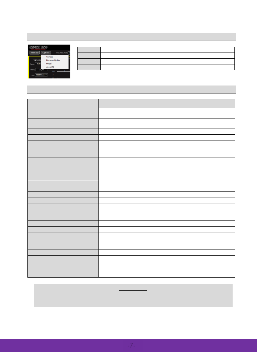
Language
Update
Help
About
Displays the software v ersion
Model
GZDSP 4-8XII
Type
8-channel signal processor (DSP) with 4 input channels
Frequency range
20 Hz – 20 KHz
SNR / line input
SNR / high leve l input
≥105 dB
THD / line input
0.002 %
THD / high lev el input
0.010 %
DSP chipset
2x Anal og Devices Sigma DSP
Sensitivity
Line input (RCA) max . 855 mV RMS
Input impedance
≥20
Ω
Output voltage / channel
≥2.5 V
Remote current
max. 500 mA
Remote input voltage
Switching voltage / speaker input
>1.3 V
Switching voltage / line input
Turn on delay
3 seconds
Recommended fuse value
2 A
Dimensions
169 x 116 x 27 mm / 6. 65 x 4.57 x 1.06” (w x l x h)
Softwa re compatibility
Microsoft Windows™ XP SP3, Vis ta, 7, 8, 8.1,10
Preset m emory
Gain range
-60 bis +6 dB
Equalizer
Time delay
0 – 8 ms / 0 – 272 cm / 0 – 107“
Crossover
Phase correction
0° / 180°
Optionally available accessory
GZDSP BTS 4-8XII
Options dropdown menu
Select the Chinese or English version of the software
Opens a window to select the update file
Opens the GROUND ZERO web p age within the br owser
Technical specifications
Sampling frequency 48 kHz / resolution 56-bit
High level input max. 8.0 V RMS
GROUND ZERO GZDSP 4-8XII
(-3 dB)
≥115 dB
Line input (RCA)
High level input 39 Ω
>10 V
k
>10 mV
6 presets (individually assignable)
8x parametric 10 band EQ (20 Hz – 20 kHz) with ad justable Q
6 / 12 / 18 / 24 dB/oct. slope with selectab le filter characteristic
GZDSP REM 4-8XII
Terms of warranty
The limited warranty for this product is covered by Ground Zero´s local distribution partners and their
terms and conditions. For further information contact your local retailer or distributor.
-7-
Page 8
GROUND ZERO GZDSP 4-8XII
DSP SERIES
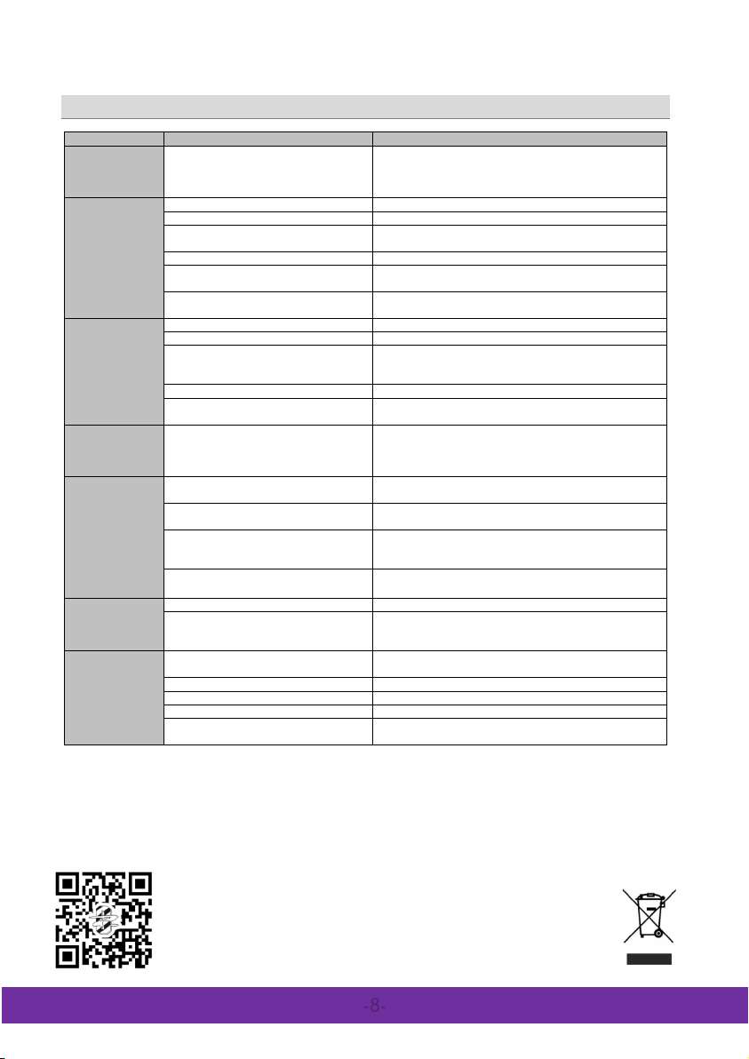
Error
Control
Help / Solution
-check the fusing
-check the ground connection and wire
signal wire no contact or broken
-check the contact or rep lace the wire
no audio signal from the head-unit
-check the audio output signal of the head-unit
-check the r emote ou t of the DSP
-check the amplifiers power supply
non oper ationa l source selected
-check the setting
activated >MUTE< function (User
Interface)
adjusted level on optional remote control
unit too low
signal wire no contact or broken
-check the contact or repl ace the wi re
no audio signal from the head-unit
-check the audio output signal of the head-unit
balance or fader control of the head-unit
in center position
wrong setup of input and output mode
-check the setting
>GAIN< level too low or >M ute<
function (user int erface) a ctive
-check the p olari ty of the s peaker connection
-check the > TIME ALI GNMENT< adjus tment
-reduce the volum e level
-check the highpass filter and slope
-select the correc t input m ode
-pay attention to the input sensitivity of the DSP unit
-reduce the volum e level of th e hea d-unit
-deactivate the >Loudness < function of the h ead-unit
>GAIN< level too high
-reduce the >GAIN< level
-select a superior quality head-unit
-let the audio store or ma nufacturer check th e head-unit
diverse power s upplies or ground
connection
-the head -unit, the DSP and each amplifier should be wired
up to a common ground and +12 Volt connection
signal wire no contact or broken
-check the contact or repl ace the wi re
head-un it defectiv e
-let the audio store or ma nufacturer check th e head-unit
amplifier defectiv e
-let the audio store or ma nufacturer check th e amplifier
DSP unit or amplifier mounted close to an
automotive control unit
-8-
Error diagnosis
No function PWR LED on?
No sound
(PWR LED on)
Single channels
with no function
Impure sound,
incorrect stereo
reproduction
Distorted sound
quality
Increas ed
noise l evel
Car specific
interferen ces
audible through
the audi o system
amplifier not switched on
not
inverted phas e of one or more spea kers
speaker overload
DSP input override (distortion)
head-uni t output overrid e (distortion)
amplifier override (clipping)
head-un it creates noise
-check the r emote wire
-check the +12 Volt connection and wire
-check the setting
-check the setting
-check the s etting of the hea d-unit
-check the setting
-check the p olari ty of the high-level input
-check the >PHASE< setting
-set the sound controls of the head-unit to center position
-check the amplifiers input sensitivity
-reduce the level
-use the optical output (if available)
-choose another mounting position
Ground Zero GmbH
Erlenweg 25, 85658 Egmating - Germany
Tel. +49 (0)8095/873 830 Fax -8310
www.ground-zero-audio.com
 Loading...