

Page 1
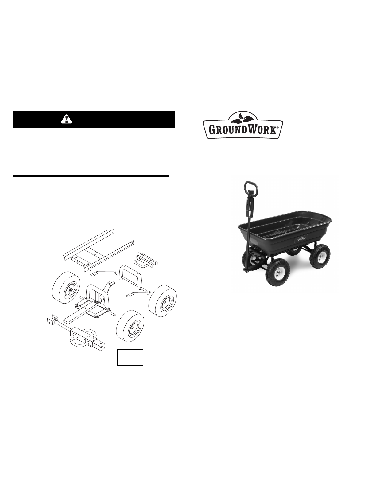
Replacement Parts List
For replacement parts, please visit us online at www.tricam.com to complete the replacement parts submission form or call our customer service
department at 1-800-867-6763, 9 a.m. - 4 p.m., CST, Monday - Friday.
B. Lock Assembly
C. Front Frame
D. Rear Axle Assembly
E. Front Axle Assembly (1)
F. 10 in Wheel
G. Handle
H. Hardware Kit
DO NOT EXCEED MAXIMUM OVERALL LOAD CAPACITY 600 LBS (272 KG.).
MAXIMUM DUMPING LOAD CAPACITY 300 LBS. (136 KG.).
WEIGHT RATING IS BASED ON AN EVENLY DISTRIBUTED LOAD.
CAUTION
U.S. Patents: 6,851,756, 7,210,697, 7,390,065,
7,441,792, 7,818,865, 7,887,141
Canada Patent: 2,503,869
Other U.S. and Foreign Patents Pending
9/11
Owners
Manual
Model GW2170D-1
• Important Safety Instructions
• Assembly Instructions
• Parts and Hardware Identification
Medium-Duty
Dump Cart
For product inquiries:
Tricam
7677 Equitable Drive
Eden Prairie, MN 55344
800-867-6763
www.tricam.com
CAUTION: Read, understand and follow ALL instructions before using this product.
WARNING: Not for recreational use. Persons should never ride in the Dump Cart.
Questions, problems, or missing parts? Before returning to your retailer, visit us
online at www.tricam.com and complete the replacement parts submission form or
call our customer service department at 1-800-867-6763,
9 a.m. - 4 p.m., CST, Monday-Friday.
H.
B.
D.
C.
E.
G.
F.
Page 2
Returning the Plastic Bed to the
Lowered Position
Rotate the plastic bed back down
to the lowered position. Make sure
the dumping release handle is
locked into place when the
cart is in the lowered position.
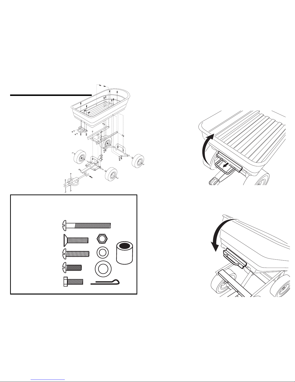
A. Tray (1)
B. Lock Assembly (1)
C. Front Frame (1)
D. Rear Axle Assembly (1)
(includes rear axle and left
and right struts)
E. Front Axle Assembly (1)
F. 10 in (25.4cm) Wheels (4)
G. Handle (1)
Parts List
A. M8x60 Bolt (1)
B. M8x40 Flat Head Bolts (2)
C. M8x40 Truss Head Bolts (2)
D. M8x20 Truss Head
Bolts(10)
E. M8x20 Hex Head Bolts (2)
F. M8 Lock Nuts (17)
G. M8 Washers (17)
H. Wheel Spacers (4)
I. 16mm Washers (4)
J. Cotter Pins (4))
Hardware List
Drawings are not to scale
Exploded Drawing for Assembly
A.
B.
D.
C.
E.
G.
F.
Using the Dumping Feature
To operate the dumping feature, pull the dumping release handle outward to release
the plastic bed from the locking mechanism. Lift up the release handle to rotate cart
upward into the dumping position.
A.
B.
D.
C.
E.
F.
G.
H.
I.
J.
Page 3
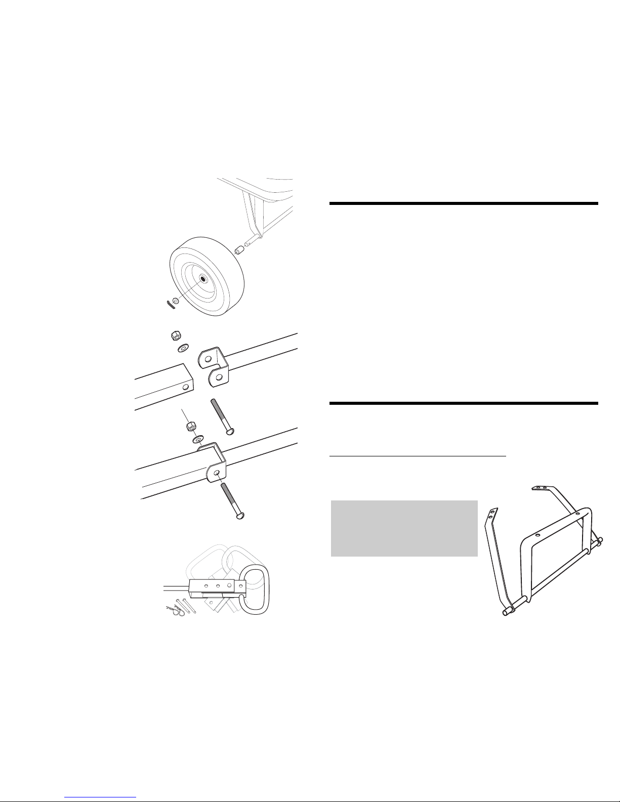
Step 7
Attach the handle to the yoke using
M8x60 bolt (1), M8 lock nut (1), and M8
washer (1).
Swivel Handle Instructions
Step 1
Remove clips and cotter pins.
Step 2
Rotate the handle and insert cotter pin.
Secure by attaching the clip.
Step 3
The second cotter pin is used to attach the
handle to the trailer hitch.
1. READ ALL INSTRUCTIONS CAREFULLY BEFORE USE. If you do not understand these
instructions, need clarification or further explanation, please call our toll free answer line for
assistance at , 1-800-867-6763 Monday through Friday 9:00 a.m. - 4:00 p.m, CST.
2. Do not load the cart with more than 600lbs (272kg). Do not use the dumping feature
of the cart with more than 300lbs (136kg). The weight rating is based on an evenly
distributed load.
3. Do not allow children to use the cart without supervision. This cart is not a toy.
4. Do not use this cart for transporting passengers.
5. This cart is not intended for highway use.
6. Do not exceed 5 mph.
7. Do not load any items on the top edges of the tray.
8. If any parts become damaged, broken or misplaced, do not use this cart until
replacement parts have been obtained.
9. Do not use this cart on surfaces or for transporting objects than can cause damage
to the pneumatic tires or tubes.
Do not inflate the tires to more than 30 PSI (2.07 BAR).
10. It is recommended that the cart be inspected for damage before each use.
11.
KKEEEEPP TTHHEESSEE IINNSSTTRRUUCCTTIIOONNSS FFOORR FFUURRTTHHEERR RREEFFEERREENNCCEE..
Your cart requires assembly. Account for all parts before beginning assembly. If any
parts are missing, damaged, or if you have any questions or need additional
instructions, DO NOT RETURN THIS PRODUCT TO THE RETAILER, visit us at
www.tricam.com to complete the replacement parts submission form or
call our customer service department at 1-800-867-6763.
Tools required for assembly: phillips screwdriver,
socket set (or two adjustable wrenches).
TOOLS NOT INCLUDED.
Important Safety Instructions
Assembly Instructions
Step 1
Locate the rear axle assembly (the left and
right rear struts are pre-assembled to the rear
axle frame as shown
NOTE: During each step of
assembly, assemble all hardware
and hand tighten. Once all the
hardware is installed for that
particular step, tighten all hardware.
Step 6
Attach the wheels by first placing the wheel spacers
(4) onto each axle, then placing the wheel (4) onto
each axle and finally placing the wheel washers (4).
Insert the cotter pins (4) into the hole at each end of
the axles and bend back the ends of the cotter
pins to keep them in place.
Page 4
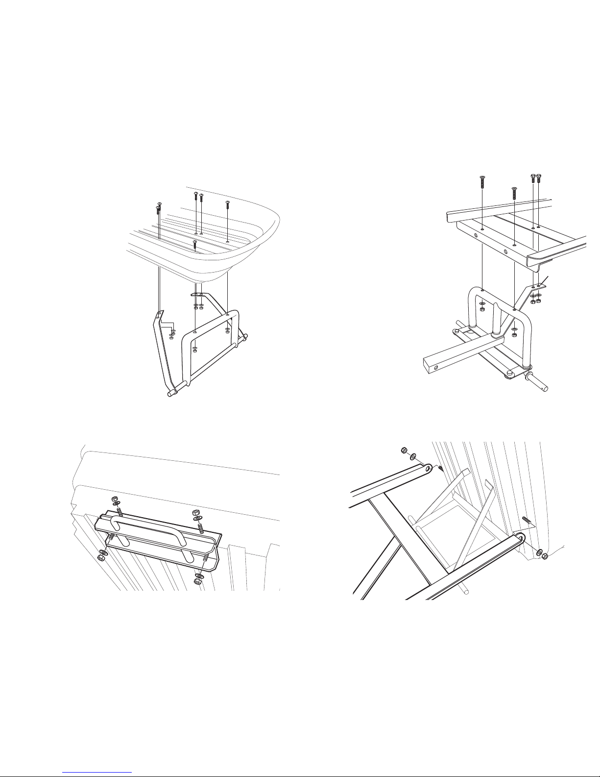
Step 4
Attach the front axle assembly to the
front frame using M8x40 Phillips flat head
bolts (2), M8 lock nuts (2), and M8
washers (2).
Attach the front axle support arm to the
frame using M8x20 hex head bolts (2), M8
lock nuts (2), and M8 washers (2).
Step 3
Attach the lock assembly to the tray using M8x20 truss head bolts (4), M8 lock nuts (4),
and M8 washers (4).
Step 2
Attach the rear axle assembly to
the tray using M8x40 truss head
bolts (2), M8 lock nuts (2), and
M8 washers (2).
Attach the left and right rear
struts to the tray using M8x20
truss head bolts (4), M8 lock
nuts (4), and M8 washers (4).
Step 5
Attach the rear axle assembly to the tray using M8x20 truss head bolts (2), M8 lock
nuts (2), and M8 washers (2).
front axle
support arm
 Loading...