

Page 1
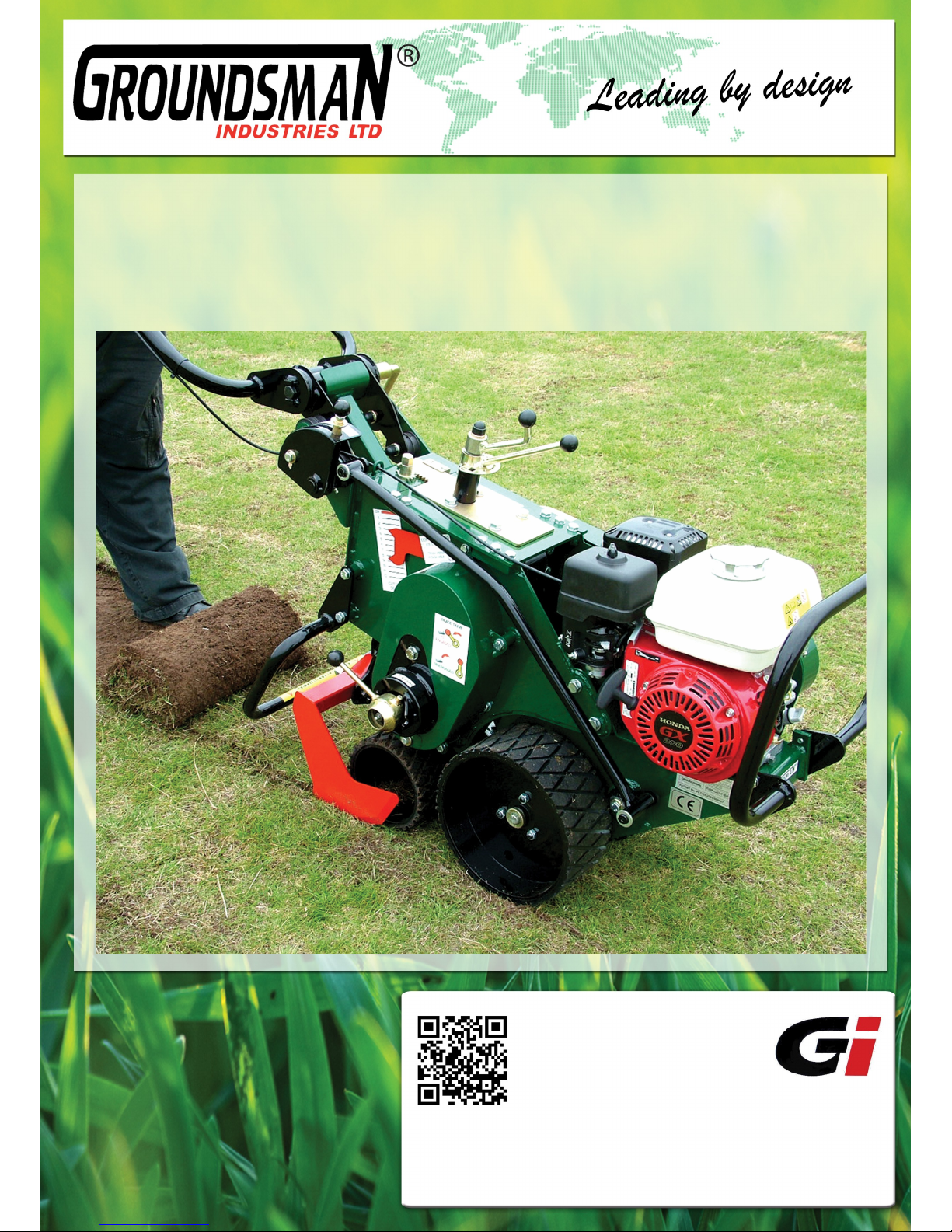
Operators Manual
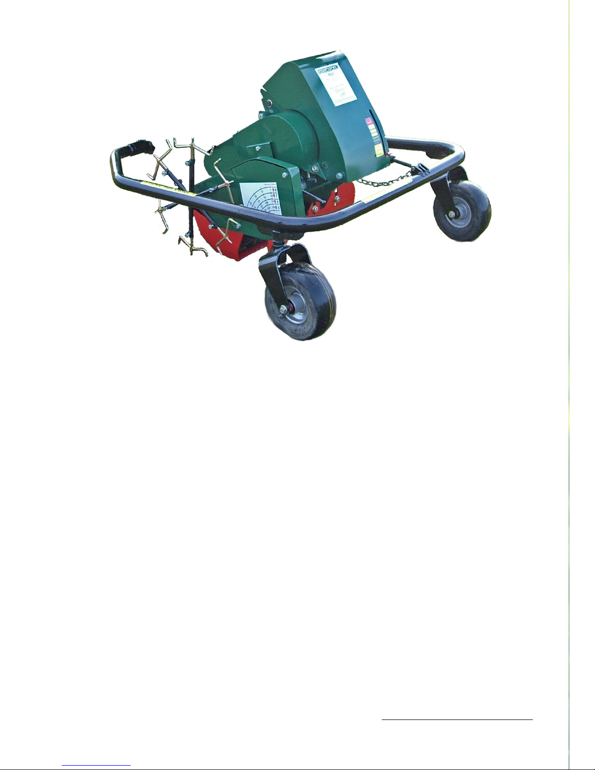
MODEL TMC48
TURF multi CUTTER
Exceptional build quality,
machines you can rely on
& great aftersales care...
OM Aug 2013
Email : [email protected]
www.groundsmanindustries.com
Tel : +44(0) 28 2766 7049
To see our full range visit
our website or give us a
call, there are no pushy
salesmen, just good
honest help & advice...
Page 2

SERIAL NUMBER DELIVERY DATE
---------------------------- ----------------------------
It is essential to quote the machine model and serial number when making service enquiries
or ordering spare parts to avoid any delay.
The serial number of your Groundsman Pedestrian Operated Turf Multi Cutter is located on
the front right side body panel if viewed from the rear of the machine.
This machine was supplied by:
Dealer address:
If you require any further advice or assistance you can contact Groundsman Industries
directly on:
Tel: +44 (0) 28 2766 7049 Fax: +44 (0) 28 2766 6855
Email: [email protected]
Website: www.groundsmanindustries.com
Page 1 Page 2
Page 3

INDEX
CONTENTS PAGE
SERIAL NUMBER 1
INDEX 2
SAFETY FIRST 3
WARRANTY 4
TECHNICAL SPECIFICATION 5
MACHINE BREAKDOWN 6
TECHNICAL INFORMATION 7, 8
OPERATOR LEVERS AND CONTROLS 9, 10
BASIC SET-UP & OPERATING INSTRUCTIONS 11, 12
CHANGING BLADES 13
RUNNING MAINTENANCE 14, 15, 16
BLADES & ACCESSORIES 17, 18, 19
Page 2
Page 4

SAFETY FIRST
1. All guards must be in place.
Always ensure that all guards are in position, properly fitted and maintained. Do not attempt to operate the
machine before making this check each time the machine is used.
2. Beware of bystanders.
Operators should be aware that it is possible that debris can exit from the sides of the machine, so this area
is best kept clear.
3. Always operate safely.
Never remove any guards or work at the any part of the mechanism while the engine is running. When tilting the machine up to rest on the chassis nose to gain access to the cutter blade, always select a stable and
level surface. Be aware that in this forward tilted position, petrol can leak through the filler cap if the tank
is full. Take care not to allow petrol spillage or cause to ignite.
4. Never operate the machine with any parts missing.
Check the machine periodically for loose or damaged parts. Always use genuine Groundsman Industries
replacement parts. Failures caused by the use of spurious replacement parts will not be covered by the
factory warranty, nor will any liability be accepted for damages or injury thus incurred.
5. Modifications.
No liability will be accepted in respect of machines modified without specific written permission from
Groundsman Industries.
6. Observe the manual.
No liability will be accepted where injury or damage is caused by using the machine in a manner other than
detailed in this manual.
Always disengage blade drive before transporting the machine
Do not start this machine or carry out any maintenance until you have read and understand the
safety and operating instructions contained in this manual.
Page 3 Page 4
Page 5

WARRANTY
Examination of the goods has been made by or on behalf of the purchaser and no warranty condition, description or representation on the part of the manufacturer is given or is to be implied or has been given
from anything said or written in the negotiations between the parties or their representative beyond those
mentioned below. Any statutory or other warrant condition, description or representation expressed or implied as to the goods is hereby expressly excluded.
In lieu, thereof the manufacturer undertakes to make good by repair or replacement at its option free of all
charge during normal working hours. Any defects in the goods arising in the manufacturer’s opinion from
faulty design, materials or workmanship which shall become apparent within a period of 24 months in the
case of machines, and 12 months in the case of spares from the date of receipt of the goods. At the termi-
nation of which period, all liability on the manufacturer’s part ceases. Provided always and the above war-
ranty is subject to the following conditions:
A. The manufacturer’s liability extents only to the repair or replacement and it accepts no liability for any
consequential or other loss, damage or injury resulting directly or indirectly from any defect in the
goods.
B. The manufacturers warranty does not extent to failures, defects or damage attributable to wear and tear,
improper adjustments, neglect, and alteration of specification or accident.
C. All defective parts must be returned to the dealer immediately together with full particulars of the de-
fects, the machine number, the hours worked and the date machine was supplied.
D. The manufacturers warranty does not extend to proprietary or other components not of its manufacture,
but it will as far as possible pass to the purchaser any benefits of any guarantee given to the manufacturer in respect of such components.
E. In the event of the rejection by the manufacturer of any claim, the part or parts returned will be de-
stroyed unless specific instructions to the contrary were given when part or parts were returned.
F. No claim will be considered if other than genuine parts manufactured by the manufacturer or its order
and listed in its catalogue are used.
G. This warranty should only be construed as strictly limited in its application and is valid only in the
country of purchase. If the goods shall change hands during the period of this warranty, this warranty
will cease to have effect.
H. The manufacturer accepts no responsibility for damage by fire or accident of any kind to any goods re-
turned under the terms of this warranty. The manufacturer does not accept responsibility for any accident occurring to such goods whilst on the premises.
I. This warranty shall cease to have effect if the purchaser removes, defaces or alters the manufacturer’s
number plate (serial number) or any other numbers or marks affixed to any Groundsman Industries Ltd
product.
J. In respect to machines sold which have been used since the date of manufacture for commercial, con-
tract, hire, rental or demonstrator purposes, the warranty on this product is limited in duration to 12
months from the date of purchase.
Page 4
Page 6

BLADES
Blade Mounting : Three Bolt Tri-Pad Mounting
Sod Cutting : Depth 8cm (3”)
Width 30cm (12”)
35cm (14”)
40cm (16”)
45cm (18”)
50cm (20”)
60cm (24”)
De-compact / Mole Drain / Trench : Depth 15cm (6”)
Adjustments : Cut Depth 0cm — 6cm infinitely variable
Cut Angle 1deg — 6deg infinitely variable
Overall Dimensions: Width 66cm (26”) At Handles
52cm (21”) At Safety Guard
Length 120cm (43”) Handles Folded
188cm (63”) Handles Open
Height 90cm (32”)
Machine Weight : 193kg (424lbs)(w/o TC4GCO attachment)
Engine : 9 HP Honda GX240
Primary Drive : Enclosed Centrifugal Clutch & Belt Drive.
Blade Drive : Central Connecting Rod and Eccentric Drive Shaft
Sealed Bearings Throughout.
Ground Drive : Oil filled worm gear clutch engaging front axle.
Oil bath chain driven rear axle.
Wheels Front : Stud mounted 13 x 650 - 6 pneumatic turf tyres.
Wheels Rear : Solid rubber diamond block tread in four widths to suit blades.
PERFORMANCE CHART (@ 3600RPM)
Page 5 Page 6
TMC48 Technical Specification
Depth
Adjustable
(Maximum)
Cutting widths
Forward
Speed
HAV Levels (Handle
Bar
Vibration)
TURF CUTTING
8cm (3”)
Mole &
De-Compact
15cm (6”)
TRENCH
16cm
SOD
30cm to 60cm
30 mtrs/min
(32 yds)
6.68 (m/s2)
Maximum
Operating Time
1.12 Hours
Page 7
Page 6
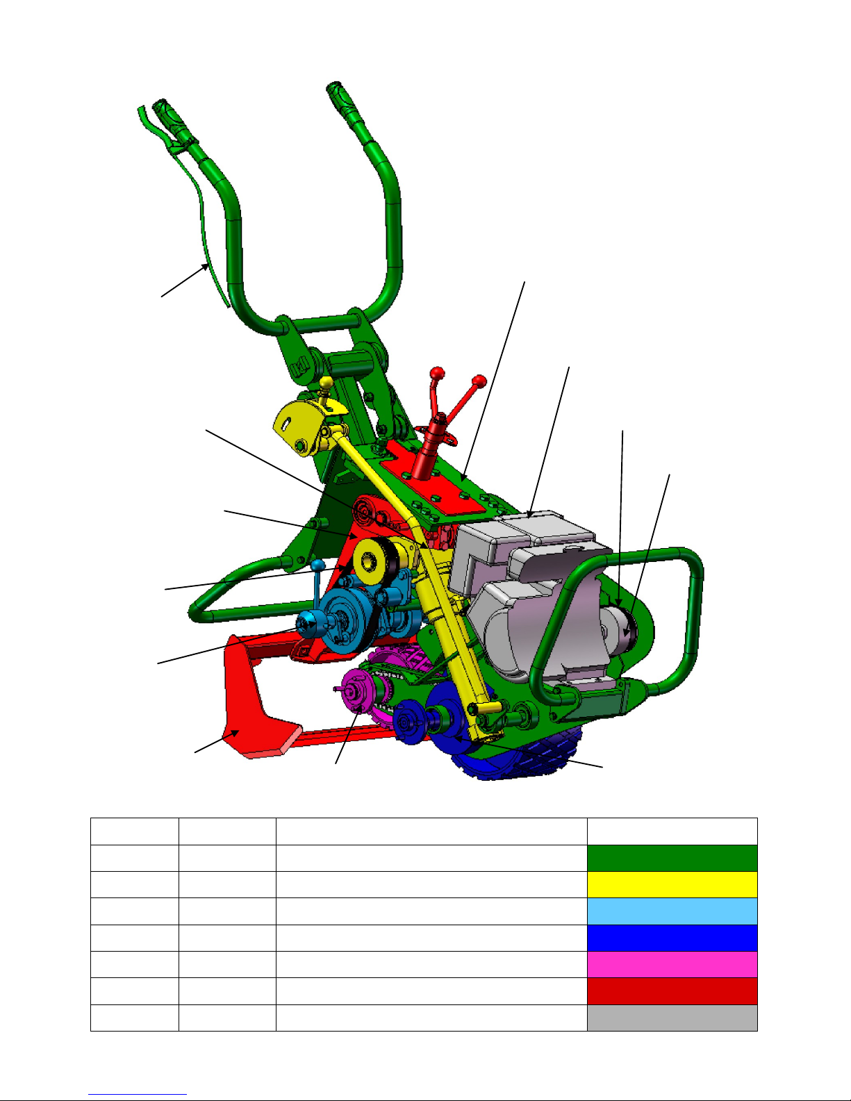
TMC48 Machine Breakdown
1. CHASSIS ASSEMBLY
7. HONDA ENGINE GX240 9 HP
BELT
ENGINE CLUTCH
4. FRONT AXLE
2. GROUND DRIVE
ASSEMBLY
BELT
3. CRANK
ASSEMBLY
5. REAR AXLE
6. BLADE ASSEMBLY
BLADE
THROTTLE CABLE
ITEM NO. PART NO. DESCRIPTION COLOUR CODE
1 BIB 001 Chassis Assembly
2 BIB 298 Ground Drive Assembly
3 BIB 319 Crank Assembly
4 BIB 253 Front Axle Assembly
5 BIB 214 Rear Axle Assembly
6 BIB 529 Blade Assembly
7 BIB 457 Engine, Clutch, Belt & Chains
Page 8

Page 7 Page 8
TMC48 Technical Information TMC48 Technical Information
With reference to the colour coded illustration on Page 6 of the TMC48 Operators
Manual Booklet
Engine, Clutch, Belt & Chains
Honda GX270 parallel 1” keyed shaft 9 HP engine fitted with a solid steel triple shoe
centrifugal clutch. The clutch is throttle lever activated and drives an ‘A’ section main drive V
-belt transmitting power from the engine to the input shaft pulley located on the far side of
the tee gearbox (yellow). The V-belt is tensioned by an adjustable jockey pulley which rides
on the inside V section tensioning the belt outward in its natural curvature rather than riding
on the back of the belt thereby minimising belt failure from splitting. The belts are easily
accessible for adjustment or replacement by removing the cover.
Ground Drive Assembly
The V belt driven input shaft runs through the sealed oil filled tee gearbox across the width
of the chassis driving a 30mm (1 ¼”) wide flat toothed belt to transmit power to the bladedrive crankshaft. The worm-gear shaft extends downwards from the tee gearbox through the
worm tube casing transmitting power to the front wheel axle (blue) by engaging on a heavy
duty 160mm (6”) diameter bronze worm wheel. The worm gear drive is engaged and
disengaged by a remote gear lever via a direct linkage rod and activating cam within the
axle casing.
Front Axle Assembly & Rear Axle Assembly
The positioning of the wheel axles within the casing maximises traction, balance and blade
ground clearance. The rear axle (purple) is chain driven from the front axle (blue). The worm
gears and drive chain are enclosed and submerged in the oil filled casing for long life and is
virtually maintenance free.
Crank Assembly
The flat toothed belt transmits power from the tee gearbox output shaft via the lever
activated plunger-pin blade drive clutch to the blade drive crankshaft. The flat belt is quiet
running, extremely long lasting and requires no lubrication. It provides a cushion drive to the
cutter-blade helping prevent damage from stones or intrusions. The blade drive flat belt is
easily accessible for adjustment or replacement by removing the belt cover. The blade drive
crankshaft is fitted with two flywheel counter-balance weights which counteract the
vibrations generated by the oscillating blade drive mechanism.
Page 9

Page 8
TMC48 Technical Information
Blade Assembly
A single connecting rod is located on the blade drive crankshaft and attaches to a high
tensile steel drive leg centrally located in relation to the cutter blade; this allows the blade to
flex at either side on impact with obstacles giving additional protection to the blade. The
blade drive connecting-rod is attached to the drive leg at a midway point above the cutter
blade allowing the crank drive to have a shorter throw keeping the moving mass to a
minimum, this in conjunction with the crank-shaft flywheels keep the vibration levels
generated by the blade drive mechanism to a minimum.
The cutter blades are attached to the blade drive leg by a unique three bolt tri-pad mounting
system which enables the operator to adjust the blade to get an equal thickness across the
width of the cut before finally tightening the blade mounting bolts. The tri-pad mounting
system can also accommodate a variety of blades and attachments. All blades are made
from hardened toughened steel and the sod undercutting blades have an arched cross
section allowing the sod to flow easier over the blade while stiffening the blade to prevent
sagging thereby maintaining thickness across the width of the sod..
The upper end of the blade drive leg is attached to a beam which enables it to be adjusted
up and down by the depth set screw to alter the depth of cut. The beam is fitted to the
chassis by a bearing block which is bolted through four slots. The blade cutting angle and the
distance from the blade wheels can be altered by loosening the four mounting bolts and
sliding the mounting block back and forth along the slots using the gear rack adjuster nut.
The blade can be positioned very close to the blade wheels with a flat cutting angle for
absolute precision cutting on fine turf even in rolling terrain or moved away from the blade
wheels increasing the throat gap and cutting angle for deeper cutting on rough or matted
grass conditions.
The machine can be fitted with a guillotine chop off attachment to measure and chop the sod
into lengths.
Chassis Assembly
Engine and blade guards are incorporated to the chassis front and rear. The chassis is
designed to allow access to the mechanisms with the minimum of dismantling. The main sub
assemblies can be removed independently if repairs or maintenance is required. The belt
drives are located external of the chassis and easily accessed by removing the belt covers.
The operator handles are mounted to the chassis by four double jointed circular rubber
mounts. These are positioned and mounted so as to allow maximum deflexion on a vertical
plane to absorb cutting vibrations in work while restricting the right / left or lateral
movement for maximum operator control to steer and guide the machine in the cut. A limit
stop is incorporated to prevent damage to the rubber joints if excessive force is applied the
operator handles. The handles can be folded over the chassis for compact storage.
Page 10
Page 9 Page 10
Operator Levers and Controls Operator Levers and Controls
A
B
B
A
B
B
C
A
C
B
A
A
A
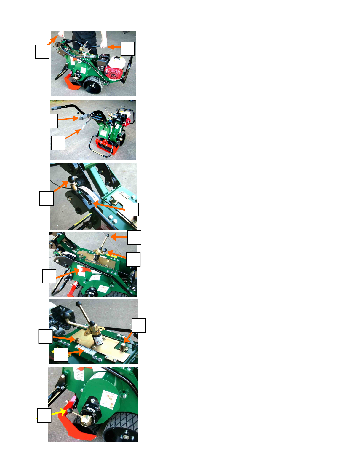
OPERATORS HANDLES FOLDED
‘A’ OPERATORS HANDLES
‘B’ OPERATORS HANDLES CLAMP BAR
OPERATORS HANDLE UNFOLDED
‘A’ OPERATORS HANDLES
‘B’ THROTTLE LEVER
GROUND DRIVE LEVER
‘A’ GROUND DRIVE ENGAGEMENT LEVER
‘B’ GROUND DRIVE ENGAGED POSITION
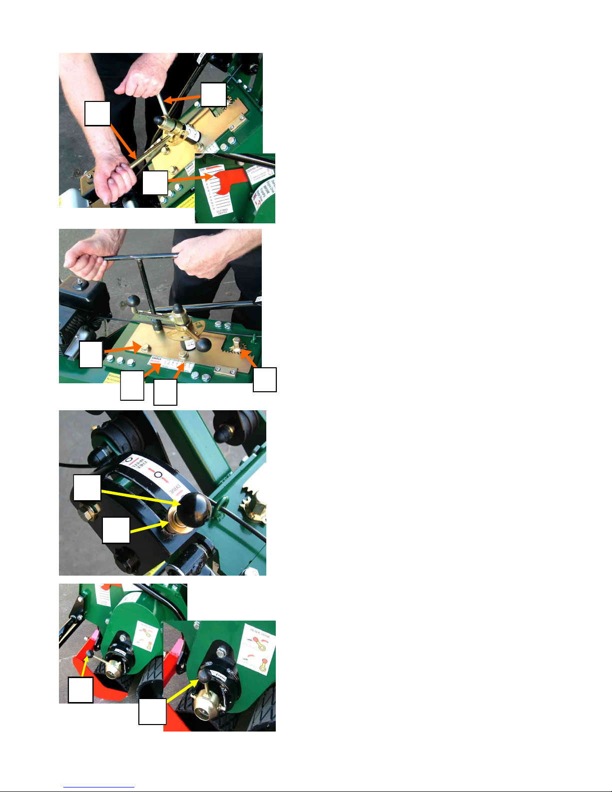
CUTTING DEPTH-SET LEVERS
‘A’ DEPTH LOCK LEVER
‘B’ DEPTH ADJUSTMENT CRANK LEVER
‘C’ DEPTH SCALE
CUTTING BLADE ANGLE ADJUSTMENT
‘A’ BLADE ANGLE CLAMP BOLT (four)
‘B’ BLADE ANGLE ADJUSTMENT NUT
‘C’ BLADE ANGLE ADJUSTMENT SCALE
BLADE-DRIVE ENGAGEMENT
‘A’ BLADE-DRIVE LEVER (engaged)
Page 11
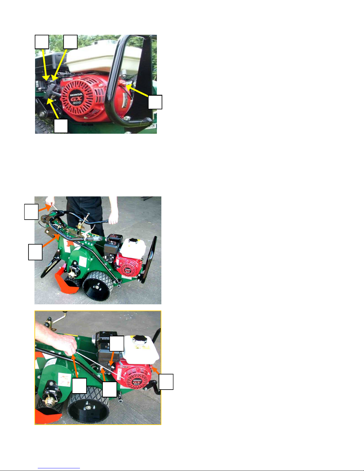
HONDA PETROL ENGINE
‘A’ ON OFF SWITCH
‘B’ CHOKE LEVER
‘C’ FUEL ON OFF LEVER
‘D’ PULL STARTER HANDLE
OPERATORS HANDLES
The operators handles ’A’ can be folded for storage
or carriage. To unfold slacken handle clamp lever
’B’ and pivot the handles up and back.
Set the operators handles at a height which is
comfortable to operate the machine. Re-tighten the
clamp lever firmly.
A
B C
D
THE ENGINE
The TMC48 Turf Cutter is fitted with a Honda GX240
9 HP Engine. Unleaded or low leaded fuel is preferred
to minimize combustion chamber deposits. Before
starting for the first time check that the engine has
been filled to the correct level with engine oil (see
running maintenance section of this manual). To start
the engine, turn the ignition switch ‘A’ on. Check
that the fuel lever ‘C’ is turned on and if the engine is
cold, turn on the choke lever ‘B’. Pull the starter cord
handle ‘D’ and when the engine starts, ease the choke
lever off.
BEFORE STARTING AND OPERATING THE
ENGINE, FAMILIARISE YOURSELF WITH
THE HONDA ENGINE MANUAL SUPPLIED
WITH THIS OPERATORS MANUAL.
Page 10
Operator Levers and Controls
Basic Setting Up and Operating Instructions
B
A
C
B
A
D
Page 12
Page 11 Page 12
Basic Setting Up and Operating Instructions Basic Setting Up and Operating Instructions
GROUND DRIVE
Ground wheel drive can be engaged or disengaged by
pulling upwards on the stem-lock plunger ’B’ and
moving the lever ’A’ forward to engage the Ground
drive or rearward to disengage. When the ground
Drive Clutch Lever is in the rearward neutral position
the wheels are free to turn for wheeling or
manoeuvring the machine. The ground drive is set
independently of the cutter drive.
DEPTH OF CUT
Tilt the machine forward to clear the blade from the
ground when adjusting the depth of cut.
Loosen the depth clamp lever ’A’ by turning it in a
clockwise direction. Turn the depth crank lever ’B’
clockwise to reduce the cutting depth, and
anticlockwise to increase it. The cutting depth is
indicated by the scale ’C’ (inset picture) When the
desired depth is set , re-clamp the depth clamp lever
’A’ firmly.
ENGAGE AND DIS-ENGAGE CUTTER DRIVE
To disengage the cutter drive push the lever ‘A’ forward until it locks into the neutral position ‘B’. When
engaging the cutter drive ensure the engine is idling
and pull the lever back to release it from the locked
neutral position. Pull the throttle lever gently to en-
able the blade clutch to fully engage drive before
increasing the power.
BLADE ANGLE ADJUSTMENT
Tilt the machine forward unto it’s nose to clear the
cutter blade from the ground. Slacken the four blade
angle clamp bolts ’A’ and turn nut ‘B’ to set the blade
angle pointer ’C’ to the required blade angle on scale
’D’. Adjust the blade angle to achieve the best traction
and cut quality. As a rule of thumb, moving the pointer
‘C’ back towards number one on the scale is best for
shallow fine cutting and forward towards number five
increases the blade angle and moves the blade away
from the blade wheel opening the throat for deeper
cutting in the rough. For Mole-draining and Decompacting adjust the blade angle to six coinciding
with the Mole-drain and De-compaction blade
symbols on the scale. Re-tighten the four clamp
bolts ‘A’ firmly before operating the machine.
A
B
A
B
A
A
C
D
C
B
B
Page 13
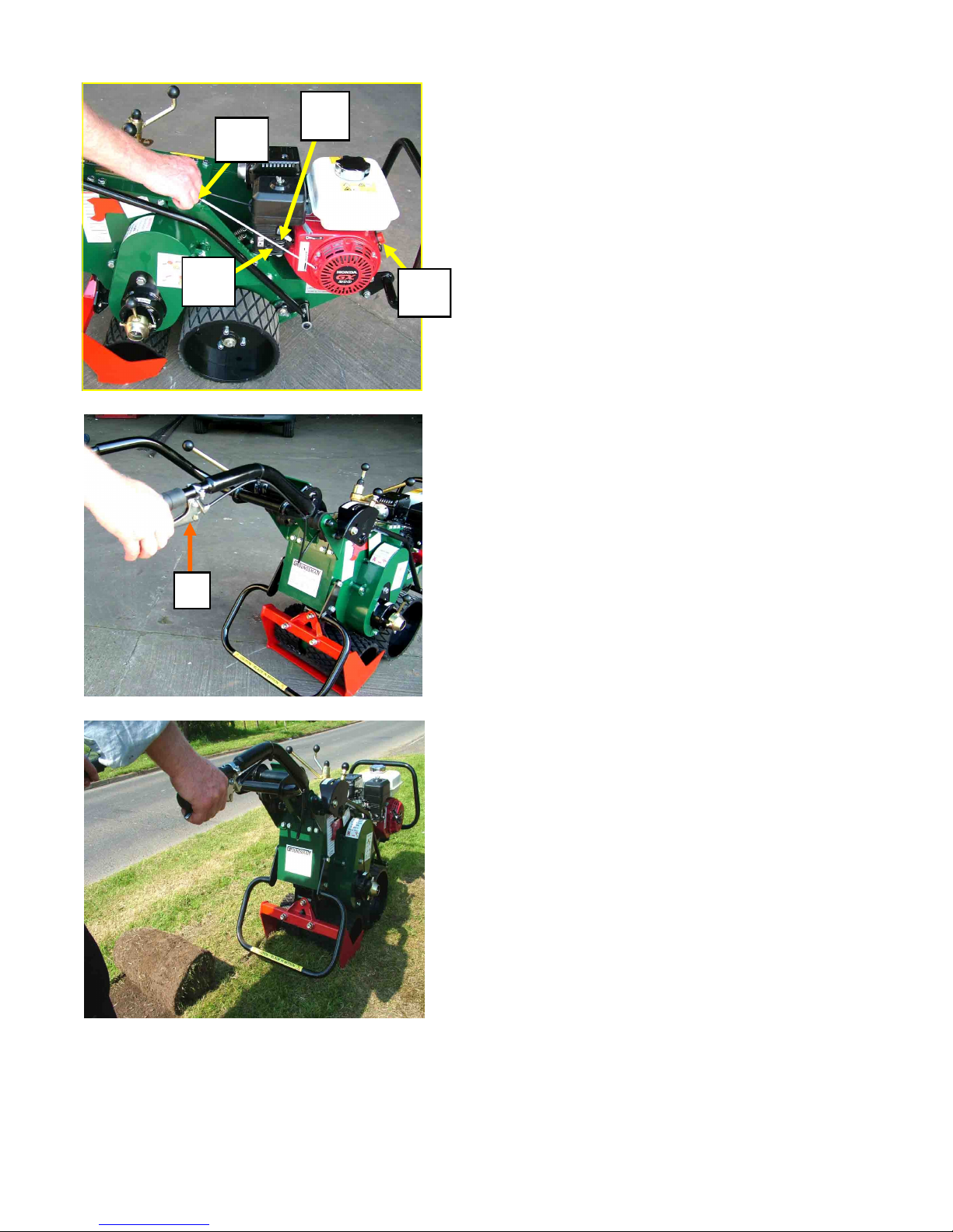
OPERATING THE MACHINE IN WORK
Follow the instructions to set the cutter depth and engage the blade cutter drive. Ensure that the ground
wheel drive is also engaged. Start the engine and
grasping the throttle lever pull upward to engage the
main drive. Apply a gentle downward pressure to the
operators handles to enter the cutter blade in the
ground then relax the handles and allow the machine to
do the work. To exit the cut, tilt the machine forward
while the drive is still engaged until the cutter blade
clears the ground.
TRANSPORTING AND MANOEUVRING
Pulling up on the throttle lever ’A’ will increase the
engine speed and engage the main drive clutch. If the
ground drive lever and blade drive toggle are set in the
disengaged (neutral) position, no drive will be transmitted to the ground wheel or the cutter blade and the
machine can be wheeled freely by the operator. Engage
the ground drive for forward transportation under
power. The cutter blade drive should remain disengaged for transporting and manoeuvring.
THE ENGINE
The TMC48 Turf multi Cutter is fitted with a Honda
GX240 9 HP Engine. Unleaded or low leaded fuel is
preferred to minimize combustion chamber deposits.
Before starting for the first time check that the engine has been filled to the correct level with engine
oil (see running maintenance section of this manual).
To start the engine, turn the ignition switch ‘A’ on.
Check that the fuel lever ‘C’ is turned on and if the engine is cold, turn on the choke lever ‘B’. Pull the
starter cord handle ‘D’ and when the engine starts, ease
the choke lever off.
BEFORE STARTING AND OPERATING THE
ENGINE, FAMILIARISE YOURSELF WITH
THE HONDA ENGINE MANUAL SUPPLIED
WITH THIS OPERATORS MANUAL.
Page 12
Basic Setting Up and Operating Instructions
A
C
B
D
A
Page 14
NOTE
See Blades and Accessories on page 17, 18 & 19
BEFORE COMMENCING TO CHANGE THE
CUTTER BLADE SWITCH THE ENGINE OFF.
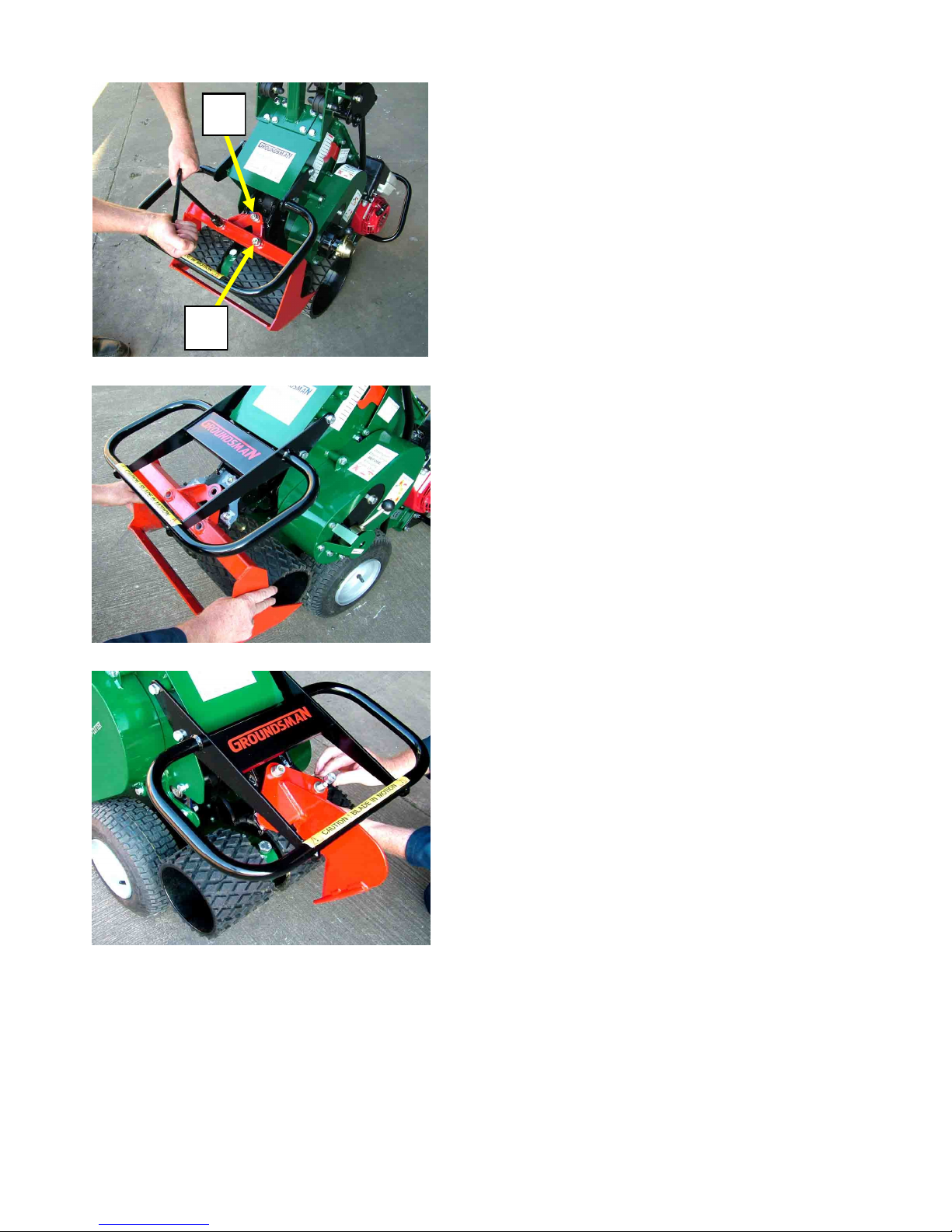
Remove and fitting the cutter blade
Tilt the machine forward to rest the chassis nose on the
ground. The Sod Cutting Blade is attached by three
bolts, two long bolts ‘A’ and one short bolt ’B’. Adjust
the blade cutting angle if necessary to give better access to the blade mounting bolts. Loosen the blade
mounting nuts using the tee wrench provided and allow
the bolts to slip forward into the mounting pad to enable the blade to slide downwards for removal. The
two longer bolts are located in the lower two holes and
the shorter bolt at the top. Ensure that the heavy washers are re-fitted and that the nuts are tightened firmly.
Ensure that the blade angle is re-set and the clamp lever
tightened firmly.
DO NOT ALLOW the blade mounting bolts to work
loose, re-check that the nuts are tight periodically when
in use.
Fitting the de-compactor or mole-drain blade
The Mole-drain and de-compactor blades are fitted in
the same manner and with the same precautions as with
the sod cutting blade described above.
PLEASE NOTE that the two longer bolts ’A’ are not
used, all three bolts are the shorter ones for these types
of blades.
Page 13 Page 14
Changing the Blades Running Maintenance
B
A
Page 15
ENGINE
Please refer to the Honda owners manual for
instructions regarding maintenance.
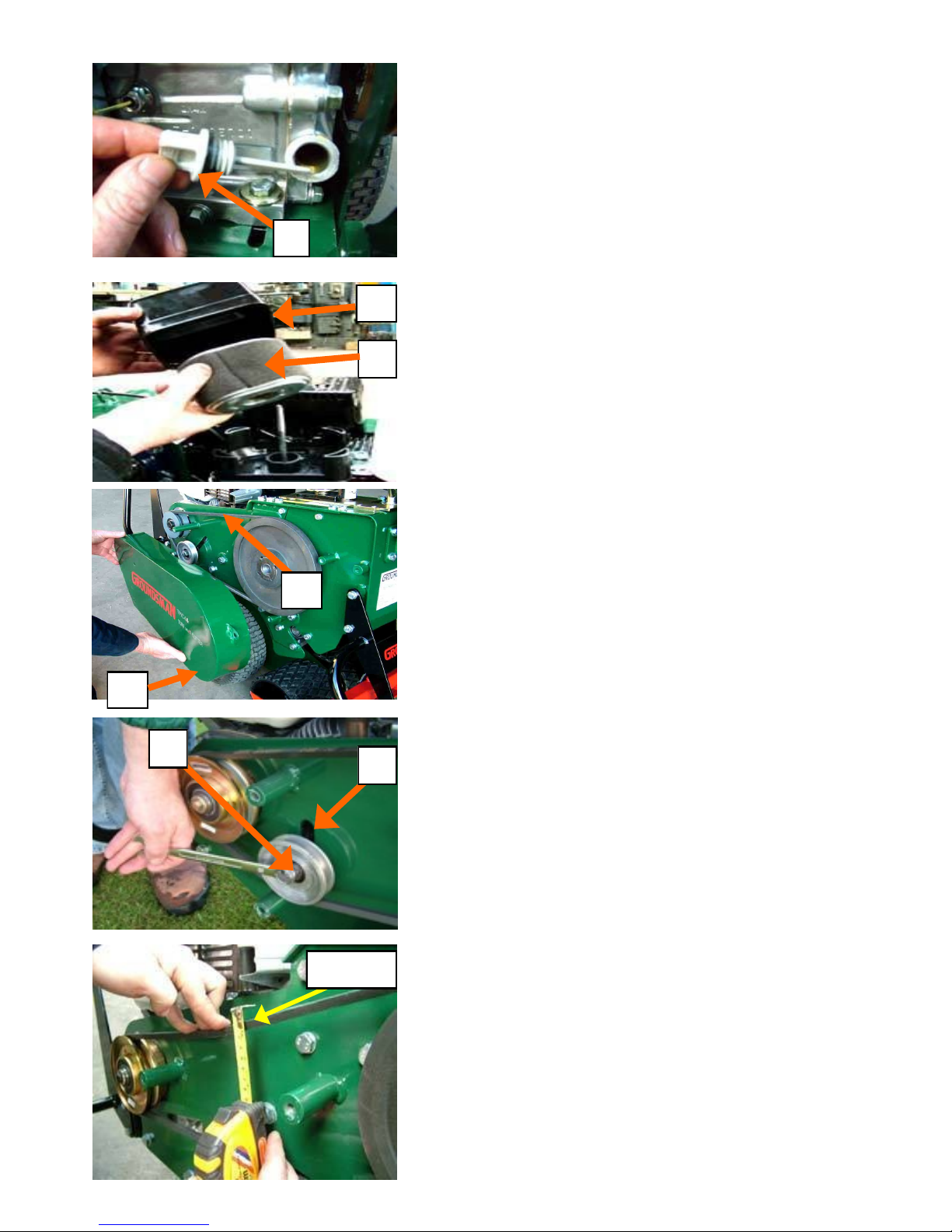
Engine Oil
The Groundsman Model TMC48 is fitted with a GX240
Honda 9 HP petrol engine. When filling or checking the oil
level, the engine should be level. Lower the machine to in
work position, unscrew the oil plug ‘A’ and dip stick located
at the front of the engine. Fill with SAE 10 W 30 or equivalent
until the oil is level with the threads on the filler hole. When
the oil plug is removed the oil should be visible on the dip
stick. Check the engine oil daily. Replace every 80 hrs or 6
months.
Air Filter
Check the air filter is clean. Undo the thumb-screw located on
the top of the air filter cover ‘B’ located on top of the engine
to expose the filter. Undo the second thumb-screw to remove
the filter. Remove the filter outer foam ’C’ and wash clean
with petrol and squeeze in a few drops of oil. The paper
element must be replaced when dirty or clogged. Check every
50 working hours depending on operating conditions.
MAIN DRIVE BELT
Removing the cover:
Check the main drive belt ‘A’ every 100 working hours. Undo
the four retaining bolts to remove the main drive belt cover
‘B’. If the belt is worn, split or cracked it must be replaced,
otherwise, follow the instructions below to check and retension the belt if necessary.
Replacing and tensioning the belt:
Slacken the belt tension pulley spindle bolt ‘C’ and slide the
tension pulley upward in the slot ‘D’ to slacken the belt for
easy removal and replacement. To re-tension the belt push the
belt tension pulley downwards in the slot. Fine adjustment can
be made to the belt tension by lightly tightening the tension
pulley and tapping on the top of the spindle behind the pulley
next to the slot using a suitable flat drift to achieve the correct
belt tension.
The correct belt tension:
Placing your fingers on top of the belt half way between the
pulleys and pressing downward, tension the belt to achieve
15mm deflection. Re-tighten the tension pulley spindle bolt
firmly.
A
C
B
C
D
15mm
A
B
Page 14
Running Maintenance
Page 16
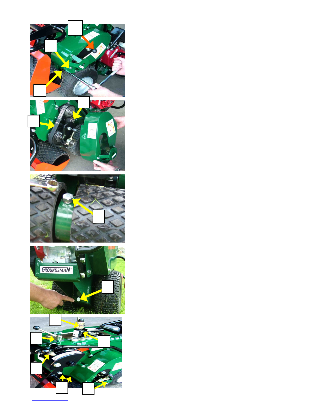
BLADE DRIVE BELT
Check and re-tension the blade-drive belt every 300 working
hours. If it is worn, split or cracked the belt must be replaced.
Access the blade-drive belt by removing the cover-guard.
Removing the cover:
Place the blade-drive engagement lever ‘A’ in the forward neu-
tral position. Undo the three main retaining bolts from guard
lugs ‘B’ plus the smaller bolt ‘C’ to remove the blade drive belt
cover.
Replacing and tensioning the belt:
Using a socket wrench, slacken the belt tensioning roller spindle
bolt ‘B’ and slide the tensioning roller along the slot to loosen
the blade-drive belt ‘A’ for removal. Slide the belt off the pul-
leys and over the blade-drive lever and bracket. To re-tension
the belt push the tensioning roller along the slot firmly against
the belt and retighten the belt tensioning roller locking spindle
bolt firmly. Replace the cover and tighten the four retaining
bolts.
GROUND DRIVE GEAR-BOX
Checking and topping up the oil level:
Check the ground drive gear-box oil level every 300 working
hours or if there is any sign of oil leakage under the machine.
With the cutter blade removed, ensure all four wheels are resting on a suitable level work surface. With a extension socket
wrench, remove oil plug ‘A’ and using a container with a filler
tube top up the gear-box oil level with EP 90 gear-oil until the
oil is level with the lip of the gear-box filler hole. Replace the
oil plug and tighten firmly.
Draining the oil :
Drain and replace the gear-box oil every 900 working hours.
With the cutter blade removed, ensure all four wheels are resting on a suitable level work surface. Place a suitable shallow oil
pan underneath the drain hole, remove the oil drain plug ‘B’ lo-
cated underneath the front of machine between the front wheels.
Tilt the machine forward to allow all the oil to drain from the
gear-box. Retighten the oil-drain plug firmly and refill the gearbox as instructed in the topping up procedure above.
Grease
Using a grease gun apply two or three pumps of general purpose
grease to the grease nipples on Lever-spindle ‘A’ Lever-housing
’B’ and Crank-bearings ’C’ at the four locations indicated. Do
not over-greasing nipple ‘A’ to avoid getting grease on the
crank drive belt.
Oil
Apply a few drops of oil to the base of Levers ‘E’ and ‘F’ and
the locking plunger on Lever ‘G’. Oil the upper end of the throt-
tle cable.
A
A
B
C
A
B
A
A
A
B
C
F
G
E
Page 15 Page 16
Running Maintenance Running Maintenance
Page 17
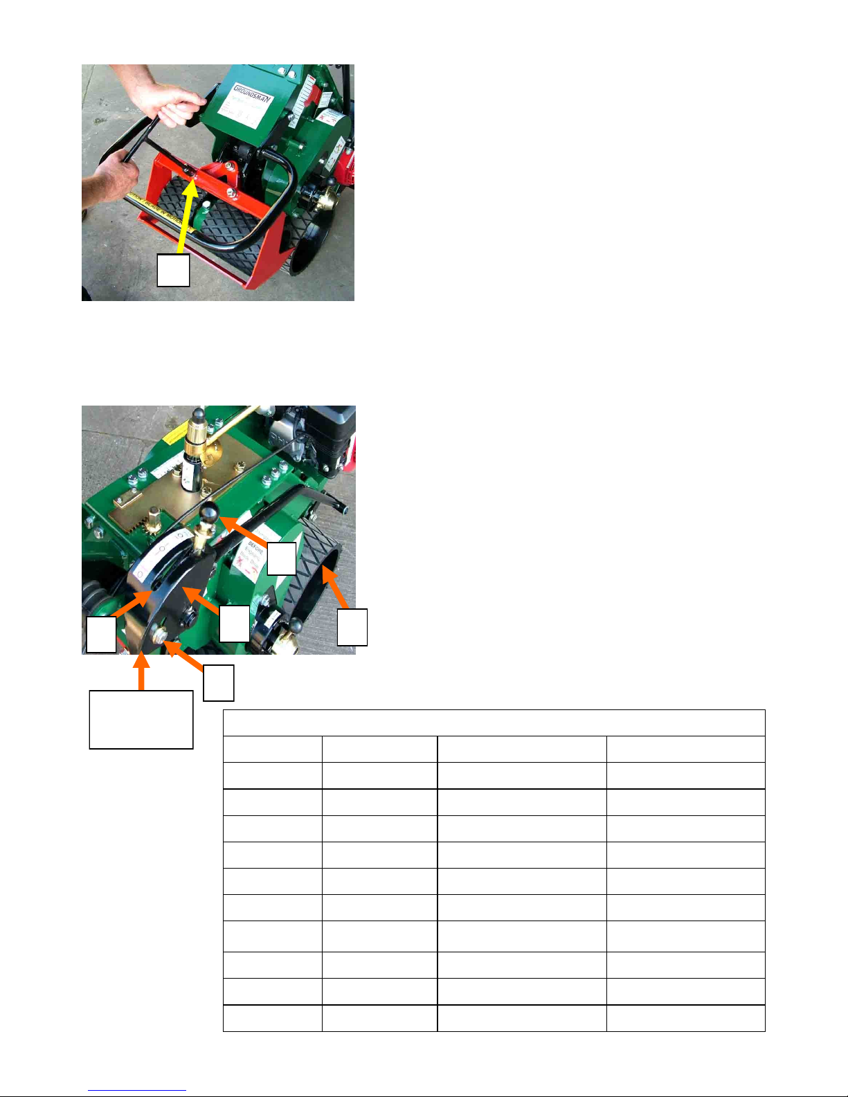
CUTTER BLADE
Check for wear and tighten the mounting bolts:
It is important not to allow the cutter blade to become
loose
The three blade mounting bolts ’A’ should be checked and
tightened five working hours after initial fitting and every 30
working hours there after. On a level surface, tilt the machine
forward to rest on the front chassis nose and use the tee
wrench supplied to tighten the bolts.. If the cutting edge on
the cutter blade cross knife or side knives is rounded and dull,
the blade should be removed for sharpening. This should be
done by a service workshop. The cutting bevel should be
ground on the upper face of the blade cross knife and on the
outermost faces of the side knives.
If the blade cross knife is worn to less than 2/3 its original
width it will not enter the ground efficiently and must be
replaced.
Page 16
Running Maintenance
A
E
D
A
C
ADJUST
UP
B
GOUND DRIVE LEVER ADJUSTMENT
After the first 20 hours working and then every 300
hours
adjust the Ground Drive Lever...
1. Place the machine on a flat level surface
2. Engage ground drive lever (A) as shown
3. Slacken clamp bolt (B) and slide the lever bracket (C) up
wards on the bolt slot (D)
4. Hold the lever bracket (C) upwards as far as possible and
tighten clamp bolt (B) FIRMLY
5. When the ground drive worm gear is new, front wheel (E)
should have no backlash movement when lever (A) is
engaged in drive.
MAINTENANCE SUMMARY
Frequency Operation Type / Quantity
Blade 30 hrs Tighten Mounting Bolts Use Tee Wrench
Oil Can 30 hrs See page 15 Penetrating Oil
Grease Gun 100 hrs See page 15 General Purpose Grease
Blade 40 hrs Sharpen or Replace if Worn See page 16 (above)
Air Filter 50 hrs Clean or Replace See Honda Manual
Engine Oil 80 hrs Top Up SAE 10 W 30
Main Belt 100 hrs Adjust or Replace See parts manual
Blade Drive Belt 300 hrs Adjust or Replace See parts manual
Gear Oil 300 hrs Top Up EP 90
Gear Lever 300 hrs Adjust See page 16 (above)
Page 18
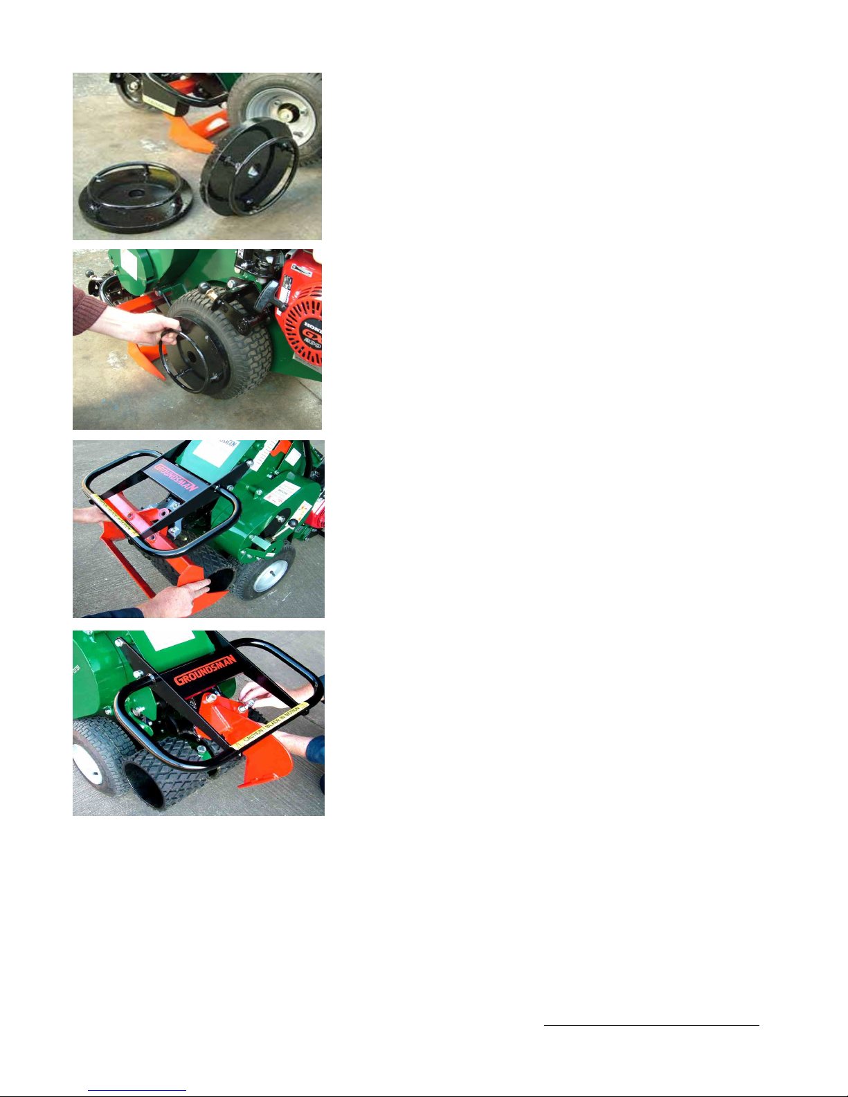
WHEEL WEIGHTS
A wheel weights kit is available for additional traction when
operating in very hard compacted conditions. The kit consists of
two disc weights and two mounting stub axles. The stub axles are
attached by the wheel hub retainer bolt and incorporate a lynchpin quick mounting method of attaching and removing the wheel
weights. The weights are fitted directly to the wheels therefore no
extra weight is felt by the operator however, when manually
lifting the machine the wheel weights should be removed.
Fitting the wheel weights:
Remove the wheel hub retainer bolts and fit the wheel weights
stub axles. Using the handles provided on the wheel weights,
align the centre hole with the stub axle and slide on the wheel
weight until it rests against the tyre. Secure the weight by
inserting the lynch-pin through the hole provided in the stub axle.
SOD CUTTING BLADES
Four widths of sod cutting blade are available for the TMC48
from 30cm (12”) 35cm (14”) 40cm (16”) 45cm (18”) and 50cm
(20”) widths.
Revetting Blades
Sod cutting blades are available with a centre knife for cutting
two strips of turf together in one pass. Sod widths 15cm (6”)
17.5cm (7”) 20cm (8”) 22.5cm (9”) 25cm (10”) and 30cm (12”)
can be cut in double strips. Sod strips in these widths can be used
for sod-wall building or revetting to create terraces or sandbunkers.
MOLE-DRAIN, DE-COMPACTION & TRENCHING
BLADES
A range of centre mounting blades are available for Drainage, De
-compaction and Trench-Cutting to 15cm (6”) depths.
See page 18 for more details about the standard blades and
accessories available for the TMC46 or view our product
accessories catalogue to see the full range.
Page 17 Page 18
Blades and Accessories
See our product accessories catalogue for more details about available blades and accessories or go to
“ACCESSORIES” on our website www.groundsmanindustries.com
Customised blade can be manufactured to your specification, contact Groundsman Industries Ltd.
Page 19
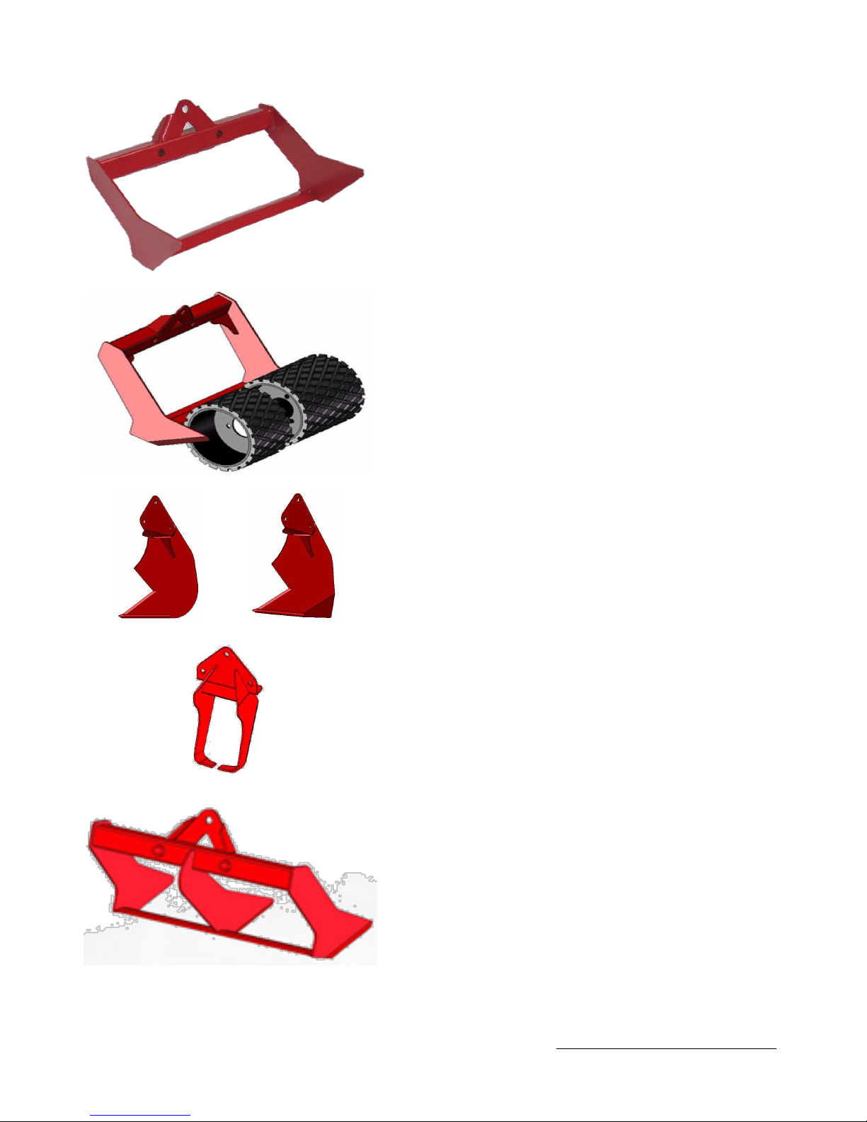
Page 18
Blades and Accessories
See our product accessories catalogue for more details about available blades and accessories or go to
“ACCESSORIES” on our website www.groundsmanindustries.com
Customised blade can be manufactured to your specification, contact Groundsman Industries Ltd.
SOD BLADES
* Symbol indicates most commonly used
Width Part Number
30cm (12”) Blade Sod Cutting TC48BS30
35cm (14”) Blade Sod Cutting TC48BS35
40cm (16”) Blade Sod Cutting ** TC48BS40
45cm (18”) Blade Sod Cutting * TC48BS45
50cm (20”) Blade Sod Cutting TC48BS50
60cm (24”) Blade Sod Cutting TC48BS60
BLADE WHEELS (SET)
* Symbol indicates most commonly used
Width Part Number
30cm (12”) Blade Wheel (set) TC48BW30
35cm (14”) Blade Wheel (set) TC48BW35
40cm (16”) Blade Wheel (set) ** TC48BW40
45cm (18”) Blade Wheel (set) * TC48BW45
50cm (20”) Blade Wheel (set) TC48BW50
60cm (24”) Blade Wheel (set) TC48BW60
MOLE-DRAIN & DE-COMPACTION BLADES
Produces a single cut on the surface cultivating
or mole-draining beneath to 15cm (6”) depth
Depth Part Number
15cm (6”) Blade Mole-drain TC48BM15
15cm (6”) Blade De-compact TC48BD15
TRENCH CUTTING BLADES
Produces a cleanly cut narrow strip of turf 10cm (4”) deep
that can be lifted out to create a trench and replaced
when work is completed.
Width Depth Part Number
16cm (7”) 10cm (4”) Blade Trench TC48BT1610
REVETTING SOD CUTTING BLADES
Two strips of sod cut with one blade
Width Part Number
2 x 15cm (2x6”) Blade Revetting TC48BR30/2
2 x 17.5cm (2x7”) Blade Revetting TC48BR35/2
2 x 20cm (2x8”) Blade Revetting TC48BR40/2
2 x 22.5cm (2x9”) Blade Revetting TC48BR45/2
2 x 25cm (2x10”) Blade Revetting TC48BR50/2
2 x 30cm (2x12”) Blade Revetting TC48BR60/2
Page 20
Guillotine Chop-off Attachment (TC4GCO)
A Guillotine attachment is available for the TMC48 which will automatically measure and chop the strips
of sod to a preset length. The guillotine blade on the attachment is crank activated and driven by an
auxiliary sprocket on the Turf Cutter machine. Guillotine blade widths are available to suit all widths of
Sod Blades. The attachment can be set to chop the length of sod infinitely from 1 metre to 5 metres long.
Widths Max Depth Part Number
30cm to 50cm 5cm (2”) TC4GCO
Page 19
Blades and Accessories
See our product accessories catalogue for more details about available blades and accessories or go to
“ACCESSORIES” on our website www.groundsmanindustries.com
Customised blade can be manufactured to your specification, contact Groundsman Industries Ltd.
Page 21

NOTES
www.groundsmanindustries.com
Page 22

NOTES
www.groundsmanindustries.com
Page 23

NOTES
www.groundsmanindustries.com
Page 24
Address
30 Ballybrakes Road
Ballymoney
Co. Antrim
Northern Ireland
BT536LG
Telephone
UK : 028 2766 7049
Int : +44 28 2766 7049
Fax
UK : 028 2766 6855
Int : +44 28 2766 6855
Global Network
Please see dealer
network page on our
website
or contact
Groundsman
Industries
Regional Dealer
Address
Telephone
Fax
Website
NOTES
Email : [email protected]
www.groundsmanindustries.com
 Loading...