

Page 1

0171942en 001
0907
Hydronic Air Heater
Pureheat
OPERATOR’S MANUAL
0171942EN
Page 2

Page 3

One Year Limited Warranty
(see your distributor to file warranty claim)
Ground Heaters, Inc. warrants that the Products described in this Limited Warranty shall be free of
defects in material and workmanship under normal use and service for a period of one year from
the Ground Heaters, Inc. invoice date to Distributor or for a period of one year from Distributor’s
invoice date to end-user, excluding pre-season orders which will have an effective warranty date of
November 15th. This Limited Warranty is expressly limited to crediting the purchase price of the
defective Product or to repairing or replacing the defective Product, at the sole option of Ground
Heaters, Inc. This warranty shall not extend to any repair work performed by anyone other than
Ground Heaters, Inc. or an authorized representative of Ground Heaters, Inc. Such credit, repair
or replacement shall be Ground Heaters, Inc.’s sole obligation and buyer’s exclusive remedy
hereunder and shall be conditioned upon Ground Heaters, Inc.’s timely receipt of warranty claim of
the alleged defect and, at Ground Heaters, Inc.’s option, return of such product to Ground Heaters,
Inc., FOB its Spring Lake, Michigan, facility. Any warranty claims received after 13 months from
warranty effective date are not valid. This exclusive remedy shall not be deemed to have failed of
its essential purpose provided Ground Heaters, Inc. is willing and able to repair or replace the
defective Product or to credit the purchase price within 90 days of the date on which Ground
Heaters, Inc. confirms that such products are defective. Use of repair or replacement parts not
manufactured by Ground Heaters, Inc. may void this warranty. Ground Heaters, Inc.’s liability
hereunder shall be limited to the contract price of that portion of the Product on which such liability
is based. The existence of a defect shall be determined by Ground Heaters, Inc. in its sole
discretion.
GROUND HEATERS, INC. SHALL NOT BE RESPONSIBLE FOR ANY LABOR CHARGES OR
LOST HEAT TRANSFER FLUID IN CONNECTION WITH WARRANTY SERVICE. USE OF ANY
ANTI-FREEZE OR HEAT TRANSFER FLUID OTHER THAN GROUND HEATERS BRAND HEAT
TRANSFER FLUID VOIDS THIS WARRANTY IN ITS ENTIRETY.
THIS WARRANTY IS EXCLUSIVE. WARRANTIES OF MERCHANTABILITY AND FITNESS FOR
A PARTICULAR PURPOSE, AND WARRANTIES ARISING FROM A COURSE OF DEALING OR
USAGE OF TRADE, ARE SPECIFICALLY EXCLUDED, AND THERE ARE NO WARRANTIES
EXPRESSED OR IMPLIED OTHER THAN THE LIMITED WARRANTY EXPRESSLY SET FORTH
HEREIN.
GROUND HEATERS, INC. SHALL NOT BE LIABLE FOR INCIDENTAL, CONSEQUENTIAL,
SPECIAL OR OTHER DAMAGES, INCLUDING BUT NOT LIMITED TO DAMAGES FOR LOSS
OF PROFITS OR PRODUCTION, OR INJURY TO PERSON OR PROPERTY. WITHOUT
LIMITING THE GENERALITY OF THE FOREGOING, GROUND HEATERS, INC. SHALL NOT BE
LIABLE FOR ANY CLAIMS BASED ON THE CONDITION, USE OR OPERATION OF THE
PRODUCTS, WHETHER BASED ON CONTRACT, TORT OR OTHER THEORIES OF LAW,
INCLUDING WITHOUT LIMITATIONS, THEORIES OF NEGLIGENCE.
The “Products” covered by this Limited Warranty include all machines manufactured by Ground
Heaters, Inc. and sold in the ordinary course of business, and all accessories therefore, which are
registered with Ground Heaters, Inc., except
for the following components: Heat Transfer Hoses,
Tires, Generator Powerheads and Engines. These are considered to be wear items and/or are
covered by warranties of the component manufacturer. NOTE: Failure to maintain proper inflation
or operating tires at speeds or under loads in excess of those recommended in the operator’s
manual may void the tire manufacturer’s warranty. Failure to fully pay for Product will void this
Limited Warranty.
No agent or employee of Ground Heaters, Inc. is authorized to modify, extend, or otherwise
change this limited warranty.
Rev. 11-22-04 - kk
Page 4

Page 5

Technical Assistance
877-799-9600
This Pureheat™ Hydronic Air Heater manual contains the
following:
1. Pureheat™ Hydronic Air Heater Operator’s Manual
2. One Year Limited Warranty
3. Pump Manufacturer’s Manual
4. Burner Manufacturer's Manual
© 2006 Ground Heaters, Inc. i V. 2, Rev. 09/01/06
Page 6

NG/LP BURNER SETUP AND INSTALLATION, FUEL
SUPPLY CONNECTION, TEST FIRING AND BURNER
ADJUSTMENT MUST
PROFESSIONAL GAS TECHNICIAN AND MUST CONFORM
TO THE REQUIREMENTS OF ALL RELEVANT LOCAL,
STATE, PROVINCIAL AND FEDERAL AUTHORITIES.
Burner setup and installation, fuel supply connection, testfiring and burner adjustment must be performed by a
licensed
requirements of local, state and federal authorities. In the
Commonwealth of Massachusetts, gas piping shall be
installed by a licensed plumber or gas fitter.
The licensed gas technician must use a manometer (to
properly adjust gas pressure) and an electronic combustion
analyzer (to properly adjust burner air intake and verify that
proper combustion parameters have been achieved). The
licensed gas technician must supply all fuel lines, fittings,
regulators, etc. necessary to connect the Pureheat
burner to the fuel source at the correct pressure and flow.
FAILURE TO HEED THIS WARNING MAY RESULT IN
LICENSED GAS TECHNICIAN REQUIRED.
professional and must conform to the
WARNING
BE PERFORMED BY A LICENSED
TM
NG/LP
AN EXPLOSION AND/OR FIRE CAUSING
PROPERTY DAMAGE, PERSONAL INJURY OR DEATH.
© 2006 Ground Heaters, Inc. ii V. 2, Rev. 09/01/06
Page 7
• Do not store or use gasoline or other
• WHAT TO DO IF YOU SMELL GAS
• Installation and service must be performed by
Operator Manual available in French language upon request. Call 877-799-9600.
WARNING: If the instructions in this
manual are not followed exactly, a fire or
explosion may result causing property
damage, personal injury or loss of life.
flammable vapors and liquids in the vicinity of
this or any other appliance.
- Do not try to light any appliance
- Do not touch any electrical switch; do not
use any phone in your building
- Immediately call your gas supplier from a
neighbor's phone. Follow the gas
supplier's instructions.
- If you cannot reach your gas supplier, call
the fire department
a qualified installer, service agency, or the gas
supplier.
Manuel de renseignements disponible en langue francaise sur demande.
Appellez le 877-799-9600.
© 2006 Ground Heaters, Inc. iii V. 2, Rev. 09/01/06
Page 8

PUREHEAT™ HYDRONIC AIR HEATER OPERATOR’S MANUAL
TABLE OF CONTENTS
Page
Technical, Checklists, Warranty Information .................................................................... i
Warnings ..................................................................................................................................... ii, iii
Specifications ............................................................................................................................ ix
List of Abbreviations................................................................................................................ x
INTRODUCTION
1.1 EXTERNAL FEATURES ................................................................................................... 1-2
1.2 INTERNAL COMPONENTS .............................................................................................. 1-3
1.2.1 Heater with Burner Options ......................................................................................... 1-3
1.2.2 Heater with Burner Detail ............................................................................................ 1-4
1.2.3 Inside Rear Doors........................................................................................................ 1-5
1.3 IDENTIFICATION .............................................................................................................. 1-6
1.4 SAFETY FEATURES......................................................................................................... 1-6
1.5 SAFETY PRECAUTIONS.................................................................................................. 1-6
1.5.1 Burner Setup, Installation and Adjustment Requirements .......................................... 1-7
1.5.2 Operators..................................................................................................................... 1-7
1.5.3 Safe Operation and Maintenance................................................................................ 1-7
1.6 REPAIR PARTS AND ACCESSORIES ............................................................................ 1-8
1.7 MAINTENANCE................................................................................................................. 1-8
1.8 OBTAINING WARRANTY SERVICE ................................................................................ 1-8
START UP, OPERATION AND SHUTDOWN
2.1 CIRCULATION SYSTEM ADVISORY............................................................................... 2-1
2.1.1 Standard Configuration Performance.......................................................................... 2-1
2.1.1.1 HX200 Heat Xchangers™ ................................................................................... 2-1
2.1.1.2 HX200 Heat Xchangers™ with Optional Booster Pump ..................................... 2-1
2.1.1.3 HX100 Heat Xchangers™ ................................................................................... 2-1
2.1.1.4 HX100 Heat Xchangers™ with Booster Pump.................................................... 2-1
2.1.1.5 HX50 Heat Xchangers™ ..................................................................................... 2-2
2.1.1.6 HX50 Heat Xchangers™ with Booster Pump...................................................... 2-2
2.1.1.7 Maximum Heat Xchanger™ Connection Capability ............................................ 2-2
2.1.2 Optional Booster Pump ............................................................................................... 2-2
2.1.3 Circulation Hose Limitations ........................................................................................ 2-2
2.1.4 Insulate Circulation Hoses........................................................................................... 2-3
2.1.5 Circulation Hose Protection ......................................................................................... 2-3
2.2 PRE-START UP CHECKS ................................................................................................ 2-3
2.2.1 Positioning ................................................................................................................... 2-3
2.2.2 Unloading HX200 Heat Xchangers™.......................................................................... 2-3
2.2.3 Unloading HX100 Heat Xchangers™.......................................................................... 2-4
2.2.4 Unloading HX50 Heat Xchangers™............................................................................ 2-4
V. 2, Rev. 09/01/06 iv © 2006 Ground Heaters, Inc.
Page 9

PUREHEAT™ HYDRONIC AIR HEATER OPERATOR’SMANUAL
TABLE OF CONTENTS (continued)
Page
2.2.5 Heat Transfer Fluid (HTF)............................................................................................ 2-4
2.2.6 Switch Positions........................................................................................................... 2-4
2.2.7 Deployment of Circulation Hoses or Option Heat Transfer Hose................................ 2-5
2.3 SETUP ............................................................................................................................. 2-5
2.4 START UP ......................................................................................................................... 2-5
2.4.1 Integrity Check............................................................................................................. 2-5
2.4.2 Warming the Heat Transfer Fluid ................................................................................ 2-6
2.4.3 Initiating Flow through Heat Transfer Hose ................................................................. 2-6
2.5 OPERATING WITH OPTIONAL ACCESSORIES............................................................. 2-7
2.5.1 Using Three HHS3004 with Booster Pump for Thawing Applications......................... 2-7
2.5.2 Using Five HHS3004 with Booster Pump for Curing and Frost Prevention Applications 2-7
2.6 MONITORING OPERATING PARAMETERS................................................................... 2-8
2.7 UNIT SHUTDOWN............................................................................................................. 2-9
2.7.1 Burner Shutdown ......................................................................................................... 2-9
2.7.2 Disconnecting Hoses from Heat Xchangers™ and Pureheat ..................................... 2-9
2.7.3 Rewinding the Circulation Hose .................................................................................. 2-9
2.7.4 Completing Unit Shutdown .......................................................................................... 2-10
2.8 CONNECTING/DISCONNECTING OPTIONAL BOOSTER PUMP.................................. 2-10
2.8.1 Connecting................................................................................................................... 2-10
2.8.2 Start Up........................................................................................................................ 2-11
2.8.3 Shutdown..................................................................................................................... 2-11
2.8.4 Disconnecting .............................................................................................................. 2-11
BURNER ADJUSTMENT AND SHUTDOWN
3.1 NATURAL GAS/LIQUID PROPANE VAPOR ................................................................... 3-1
3.1.1 Burner Adjustment ....................................................................................................... 3-1
3.1.1.1 Fuel Pressure Adjustment ................................................................................... 3-2
3.1.1.2 Air Setting and Adjustment .................................................................................. 3-2
3.1.1.3 O
Content Sampling ........................................................................................... 3-3
2
3.1.1.4 Smoke Spot Sampling ......................................................................................... 3-3
3.1.2 Burner Shutdown ......................................................................................................... 3-3
3.2 DIESEL/FUEL OIL ............................................................................................................. 3-3
3.2.1 Burner Adjustment ....................................................................................................... 3-3
3.2.1.1 Fuel Pressure Adjustment ................................................................................... 3-4
3.2.1.2 Air Setting and Adjustment .................................................................................. 3-4
3.2.1.3 O
Content Sampling ........................................................................................... 3-4
2
3.2.1.4 Smoke Spot Sampling ......................................................................................... 3-4
3.2.2 Burner Shutdown ......................................................................................................... 3-5
© 2006 Ground Heaters, Inc. v V. 2, Rev. 09/01/06
Page 10

PUREHEAT™ HYDRONIC AIR HEATER OPERATOR’S MANUAL
TABLE OF CONTENTS (continued)
Page
MAINTENANCE
4.1 ADDING HEAT TRANSFER FLUID.................................................................................. 4-1
4.1.1 To Clear a “LOW LEVEL FAULT”................................................................................ 4-1
4.2 BURNER INSTALLATION/CHANGEOVER ..................................................................... 4-2
4.2.1 From NG/LP to Diesel/Fuel Oil .................................................................................... 4-2
4.2.1.1 Installation ........................................................................................................... 4-2
4.2.1.2 Setup ................................................................................................................... 4-3
4.2.2 From Diesel/Fuel Oil to NG/LP ................................................................................... 4-3
4.2.2.1 Installation ........................................................................................................... 4-4
4.2.2.2 Setup ................................................................................................................... 4-4
4.3 HIGH ELEVATION OPERATIONS.................................................................................... 4-5
4.4 RECOMMENDED FUELS ................................................................................................. 4-5
4.5 SUMMER STORAGE INSTRUCTIONS ............................................................................ 4-6
4.6 PRE-SEASON MAINTENANCE........................................................................................ 4-6
TRANSPORTING THE PUREHEAT™ HYDRONIC AIR HEATER
5.1 TOWING............................................................................................................................. 5-1
5.2 AERIAL LIFTING............................................................................................................... 5-1
5.3 TRANSPORTING on a FLATBED.................................................................................... 5-1
5.4 COMMON MECHANICAL INSPECTIONS PRIOR TO TRANSPORTING....................... 5-1
TROUBLESHOOTING
6.1 TROUBLESHOOTING CHART ......................................................................................... 6-1
6.2 HTF LOW LEVEL FAULT AND LIGHTS .......................................................................... 6-3
6.2.1 Low Level Shutdown Device ....................................................................................... 6-3
6.2.2 Testing the Low Level Shutdown Device .................................................................... 6-3
6.3 BURNER CONTROL LOCKOUT ...................................................................................... 6-4
6.3.1 Gas Burner Control...................................................................................................... 6-4
6.3.2 Oil Burner Control ........................................................................................................ 6-4
V. 2, Rev. 09/01/06 vi © 2006 Ground Heaters, Inc.
Page 11

PUREHEAT™ HYDRONIC AIR HEATER OPERATOR’SMANUAL
TABLE OF CONTENTS (continued)
Page
APPENDIX A
PUREHEAT SCHEMATIC AND WIRING DIAGRAM SYMBOL LEGEND .................................A-1a
PUREHEAT SCHEMATIC AND WIRING DIAGRAM SYMBOL LEGEND .................................A-1b
PUREHEAT SCHEMATIC AND WIRING DIAGRAM SYMBOL LEGEND ................................. A-1c
PUREHEAT CONTROL PANEL EXTERIOR LAYOUT.................................................................A-2
PUREHEAT TEMPERATURE CONTROL..................................................................................... A-3
PUREHEAT CONTROL PANEL DOOR INTERIOR LAYOUT...................................................... A-4
PUREHEAT MAIN CONTROL PANEL - EXTERIOR COMPONENT FUNCTION
AND IDENTIFICATION ............................................................................................................. A-5
PUREHEAT MAIN CONTROL PANEL INTERIOR COMPONENT LAYOUT...............................A-6
PUREHEAT MAIN CONTROL PANEL INTERIOR COMPONENT
FUNCTION AND IDENTIFICATION.......................................................................................... A-7
PUREHEAT WIRING SCHEMATIC – CIRCUIT 1 ........................................................................A-8
PUREHEAT WIRING SCHEMATIC - CIRCUIT 1 WITH DIESEL BURNER .................................A-9
PUREHEAT SAFETY CONTROLS – DIESEL BURNER WIRING .............................................A-10
PUREHEAT WIRING SCHEMATIC - CIRCUIT 1 WITH NP/LP BURNER.................................. A-11
PUREHEAT DIESEL BURNER CONTROL SEQUENCE OF OPERATION
AND LOCKOUT ...................................................................................................................... A-12
PUREHEAT SAFETY CONTROLS NG/LP BURNER WIRING DIAGRAM ................................A-13
PUREHEAT WIRING SCHEMATIC – CIRCUIT 2 .......................................................................A-14
PUREHEAT SCHEMATIC - AUXILIARY PUMP PANEL (P/N A109-199).................................. A-15
PUREHEAT CIRCULATION - BOOSTER PUMP MOTOR WIRING...........................................A-16
PUREHEAT REWIND MOTOR WIRING .....................................................................................A-17
PUREHEAT SAFETY CONTROLS LOW LEVEL SHUTDOWN DEVICE (P/N E100-198) ........A-18
HX200 HEAT XCHANGER™ WIRING DIAGRAM...................................................................... A-19
HX100 HEAT XCHANGER™ WIRING DIAGRAM...................................................................... A-20
HX50 HEAT XCHANGER™ WIRING DIAGRAM........................................................................ A-21
PUREHEAT TRAILER JUNCTION BOX AND BATTERY WIRING............................................ A-22
PUREHEAT TRAILER WIRING ...................................................................................................A-23
PUREHEAT NG/LP BURNER COMPONENT IDENTIFICATION (P/N P100-673)..................... A-24
PUREHEAT NG/LP BURNER (P/N P100-673)
GAS PRESSURE CHECKING AND ADJUSTING ................................................................ A-25
PUREHEAT DIESEL BURNER COMPONENT IDENTIFICATION (P/N P100-690).................. A-26
SUGGESTED METHOD FOR SECURING THE PUREHEAT ONTO A TRUCK BED ............... A-27
PUREHEAT HOSE REWIND PARTS IDENTIFICATION............................................................ A-28
© 2006 Ground Heaters, Inc. vii V. 2, Rev. 09/01/06
Page 12

PUREHEAT™ HYDRONIC AIR HEATER OPERATOR’S MANUAL
TABLE OF CONTENTS (continued)
Page
APPENDIX B
PUREHEAT AIR AND SURFACE HEATING ACCESSORIES.....................................................B-1
BOOSTER PUMP TO PUREHEAT CONNECTING ......................................................................B-2
HX200 HEAT XCHANGER™ TO PUREHEAT CONNECTION LAYOUT ....................................B-3
HX100 HEAT XCHANGER™ TO PUREHEAT CONNECTION LAYOUT ....................................B-4
HX50 HEAT XCHANGER™ TO PUREHEAT CONNECTION LAYOUT ......................................B-5
PUREHEAT 18,000 SQ. FT THAW LAYOUT
(THREE HHS 3004’S AND THREE 4-PORT MANIFOLDS).................................................B-6
PUREHEAT 30,000 SQ. FT CURE LAYOUT
(FIVE HHS 3004’S AND FIVE 4-PORT MANIFOLDS) .........................................................B-7
PUREHEAT 45,000 SQ. FT FROST PREVENTION LAYOUT
(FIVE HHS 3004'S AND FIVE 4-PORT MANIFOLDS)..........................................................B-8
PUREHEAT VALVE POSITIONS FOR ADDING HTF (MACHINE IN USE).................................B-9
PUREHEAT VALVE POSITIONS FOR ADDING HTF (MACHINE NOT IN USE) ......................B-10
PUREHEAT QUICK-CONNECT AND CAM-LOCK CARE AND MAINTENANCE.....................B-11
APPENDIX C
PUREHEAT APPLICATIONS AND CAPACITIES ....................................................................... C-1
V. 2, Rev. 09/01/06 viii © 2006 Ground Heaters, Inc.
Page 13
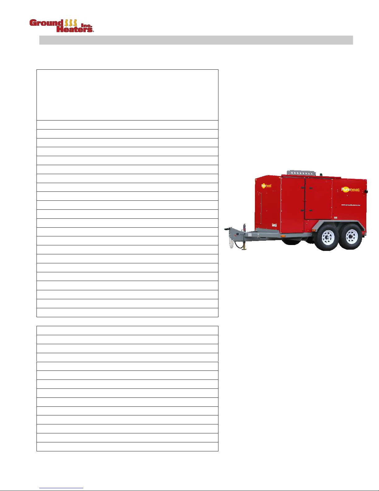
PUREHEAT™ HYDRONIC AIR HEATER
OPERATOR’S MANUAL SPECIFICATIONS
SPECIFICATIONS
Dimensions
and Capacities
Length 172 in. (437 cm)
Width 93 in. (236 cm)
Height 93 in. (236 cm)
Ground Clearance 9 in. (23 cm)
Weight 7,155 lbs (3,248 kg)
Optional Diesel Fuel Tank 435 US gallons (1,647 liters)
Weight with Optional Diesel Fuel Tank 11,230 lbs (5,098 kg)
Heat Transfer Fluid 145 US gallons (549 liters)
Pump, 1.5 hp Centrifugal 1
Circulation Hose Total: 1,000 ft (305 m) (see breakdown below)
4 x 100 ft [30 m]
4 x 50 ft [15 m]
Hose Reel 1
Hose Rewind 120 VAC, w/12 VDC clutch
Circulation Loops 5
Tires LT235/85R16
Tire Inflation 80 psig (752 kPa) cold
Hitch 3 in. Pintle or 2 5/16 in. Ball
Heat Exchangers 200,000 BTU/H (2,400 cfm) 4
100,000 BTU/H (1,315 cfm) 8
50,000 BTU/H (710 cfm) 16
Remote Manifold (not included with HX200 package) 4
Loading Ramp (not included with HX50 package) 1
On-Board Manifold (Supply/Return) 1
Lifting Bail Standard
Performance (choice of fuels)
Burner Orifice (NG/LP Burner) 9/16 in
Propane, Input 860,000 BTU/H
Natural Gas, Input 860,000 BTU/H
Burner Nozzle (Diesel Burner) 5.0 60º A (solid)
Diesel, Input 860,000 BTU/H
Efficiency 83%
Temperature Control Digital
Fuel Consumption During Burner Operation:
(Propane) 344 CFH
(Natural Gas) 860 CFH
(Diesel) 6.1 GPH
Electrical Requirement 1 x 15 amp. and 1 x 20 amp. x 120 VAC
Normal Operating Temperature 180ºF (82 ºC)
V. 2, Rev. 09/01/06 ix © 2006 Ground Heaters, Inc.
Page 14

PUREHEAT™ HYDRONIC AIR HEATER OPERATOR’S MANUAL
LIST OF ABBREVIATIONS
The following is a list of abbreviations used throughout the Operator’s Manual:
Abbreviation/Symbol
amp. ampere (measurement of electrical current)
asl above sea level
BTU British Thermal Unit (measurement of heat energy)
°C degrees Celsius (metric measurement of temperature)
CFM Cubic Feet per Minute (measurement of air flow)
cm centimeter (1/100
CSA Canadian Standards Association
°F degrees Fahrenheit (measurement of temperature)
ft foot/feet (measurement of length/distance)
2
square foot/square feet (measurement of area)
ft
ft-lbs foot pounds (measurement of torque)
gph gallons per hour (measurement of liquid flow)
GFI Ground Fault Interrupt/interrupter (protection device)
GHI Ground Heaters, Incorporated
GVWR Gross Vehicle Weight Rating
HHS Ground Heaters Hose Handling System
hr hour (measurement of time)
HTF Ground Heaters Heat Transfer Fluid
Hz Hertz (measurement of frequency)
ID measurement of Inner Diameter
in. inch/inches (measurement of length/distance)
kg kilogram (metric measurement of weight)
Kilo-Cal Kilo-Calorie = 1000 Calories (metric measurement of heat energy)
kPa kilo-Pascals (metric measurement of pressure)
kW kilo-Watt (measurement of electrical power)
lb pound (measurement of weight)
LWCO Low Water Cut Off Device
m meter (metric measurement of length/distance)
MGV Main Gas Valve (NG / LP Fuel)
mm millimeter (1/1000
NHTSA National Highway Transportation Safety Administration
psig pounds per square inch gauge (measurement of pressure)
Rev. Revision
TC Temperature Controller
USDOT United States Department of Transportation
V. Version
VAC Volts, Alternating Current
VDC Volts, Direct Current
Term/Meaning
th
of a meter)
th
of a meter)
V. 2, Rev. 09/01/06 x © 2006 Ground Heaters, Inc.
Page 15

PUREHEAT™ HYDRONIC AIR HEATER OPERATOR’S MANUAL – SECTION 1
INTRODUCTION
The Pureheat™ Hydronic Air Heater provides temporary air heat, thaws frozen ground, cures concrete
and provides frost prevention at ambient temperatures below 40°F (5°C). Ground Heaters, Inc.’s
revolutionary technology enables construction activities to continue throughout the cold weather months.
The Pureheat™ Hydronic Air Heater is equipped with a 5-Port On-Board Manifold and 1,000 ft (396 m) of
1 in. (25 mm) ID Red Circulation Hose Assemblies with Quick-Connects (QCs). The standard equipment
package includes the following lengths of Circulation Hoses: Two (2) 200 ft (61 m), Four
Four (4) 50 ft (15 m)
. The optional diesel or gas Burner heats the Heat Transfer Fluid (HTF) to 180°F
(82°C). The HTF is continuously circulated through the Circulation Hoses in a vented, closed-loop
system.
With standard equipment, the Pureheat:
(Refer to Appendixes B and C)
• Provides remote space heating for up to 1,200,000 ft3 (48,235 m 3) of building space.
Using GHI’s optional Booster Pump and Auxiliary Pump Panel, Three (3) Hose Handling System 3004
(HHS3004) with Twelve (12) 750 ft (228 m) 5/8 in. ID Heat Transfer Hoses (HTH) and three 4-Port
Remote Manifolds, the Pureheat will:
• Thaw
up to 18,000 ft2 (1,674 m2) of frozen ground per application using 24 in. (60 cm) hose
spacing.
• Thaw
up to 9,000 ft2 (837 m2) 75% to 100% faster using 12 in. (30 cm) hose spacing
(4) 100 ft. (30 m ),
Using GHI’s optional Booster Pump and Auxiliary Pump Panel, Five (5) Hose Handling System 3004
(HHS3004) with Twenty (20) 750 ft (228 m) 5/8 in. ID Heat Transfer Hoses (HTH) and Five (5) 4-Port
Remote Manifolds, the Pureheat can:
• Cure
all types of concrete placements, including slabs on grade, elevated slabs, tilt-up walls,
poured walls, columns, footings, bridge decks, etc. up to 30,000 ft
2
(2,790 m2) per application
using 24 in. (60 cm) hose spacing.
• Provides Frost Prevention
up to 45,000 ft2 (4,186 m2) per application using 36 in. (91 cm) hose
spacing.
The Pureheat™ Hydronic Air Heater Model Pureheat:
• Heats
workspace easily & economically:
• Input of 860,000 BTUH.
• Fuel flexible; choice of natural gas, propane or diesel.
• Takes only minutes to change over from one fuel to another.
• Provides pure, dry, hot air
• Removes excess moisture
• Provides pure, clean air
• Is self-contained
• Is rental friendly
– all system components are on One (1) trailer.
– easy setup and uses only One (1) 15 amp. And One (1) 20 amp. 120 volts AC
– no moisture added to workspace; prevents mold and mildew.
– dry / warm air removes moisture from workspace and building materials.
– no combustion by-products in workspace.
circuits.
• Is multi-functional
– with accessories, this system can be used as a surface heater.
V. 2, Rev. 09/01/06 © 2006 Ground Heaters, Inc. 1- 1
Page 16
PUREHEAT™ HYDRONIC AIR HEATER OPERATOR’S MANUAL – SECTION 1
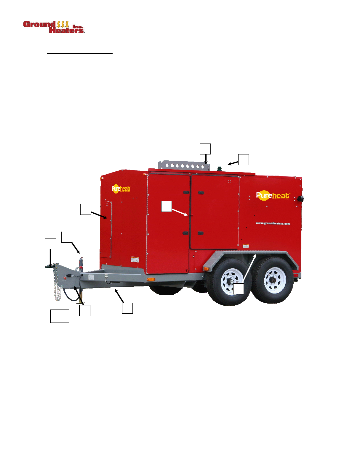
1.1 EXTERNAL FEATURES
1. Adjustable 3 in. (76 mm) Pintle Style Hitch or 2
2. Lifting Bail
3. Door Tieback
4. Lockable Doors
5. Electric Brakes with Breakaway Switch
6. Performance Monitoring Light
7. 5-Port On-Board Manifold Door
8. Heavy Duty Jack-Stand
9. Heavy Duty Fenders
7
(Photo 1-1)
5
/16 in. (59 mm) Ball
2
6
4
1
1-1
8
9
5
3
1- 2 © 2006 Ground Heaters, Inc. V. 2, Rev. 09/01/06
Page 17
PUREHEAT™ HYDRONIC AIR HEATER OPERATOR’S MANUAL – SECTION 1
1.2 INTERNAL COMPONENTS
(Photos 1-2 through 1-6)
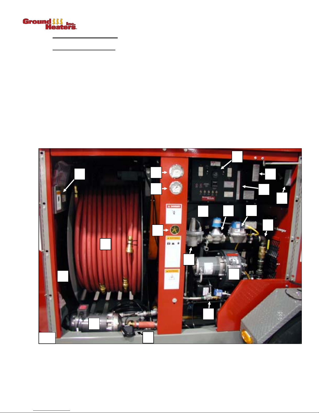
1.2.1 Heater with Burner Options
The following components are accessed via the side door:
1. Main Control Panel 10. Main Pump
2. Hydronic Heater and Expansion Tank (not shown) 11. Rewind Foot Pedal
3. Natural Gas (NG)/Liquid Propane (LP) Burner 12. Return Temperature Gauge
4. NG/LP Gas Train 13. Pressure Gauge
5. NG/LP Gas Pressure Regulator 14. Return Flow Indicator
6. NG/LP Main Gas Valve 15. Operator’s Manual Holder
7. NG/LP Secondary Gas Valve 16. Performance Monitoring Power Receptacle
8. NG/LP Pilot Gas Valve 17. Low Level Shutdown Device
9. Hose Reel with 1,000 ft (305 m) 1 in. ID 18. HTF Sight Gauge and Decal
Red Circulation Hoses with Quick-Connects (QCs) 19. Optional Auxiliary Pump Panel (not shown)
15
(Photo 1-2)
12
13
1
17
18
16
1-2
19
10
2
14
9
5
8
11
6
3
7
4
V. 2, Rev. 09/01/06 © 2006 Ground Heaters, Inc. 1- 3
Page 18
PUREHEAT™ HYDRONIC AIR HEATER OPERATOR’S MANUAL – SECTION 1
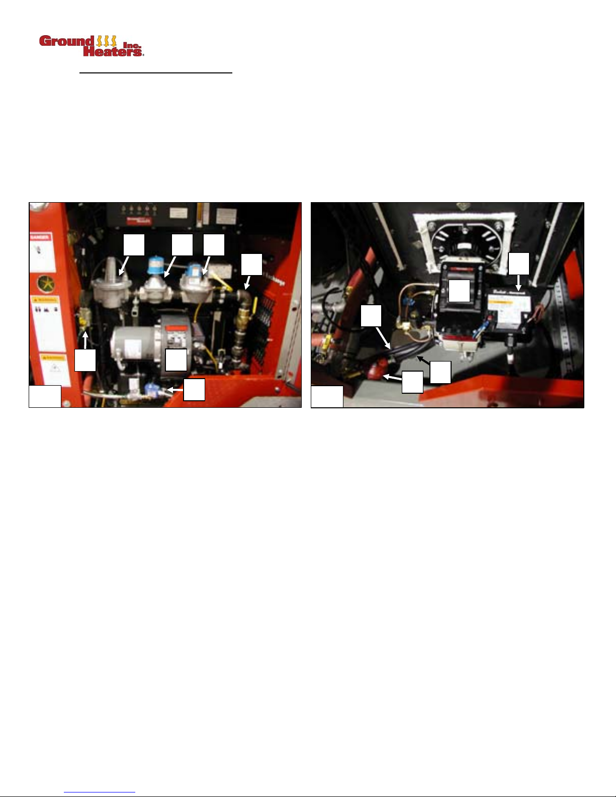
1.2.2 Heater with Optional Burner Detail
The following components are accessed via the Side Door:
1. Natural Gas (NG)/Liquid Propane (LP) Supply 8. NG/LP Gas Train
Gas Connection 9. NG/LP Burner Control (not shown)
2. NG/LP Gas Pressure Regulator 10. Diesel Burner
3. NG/LP Main Gas Valve 11. Diesel Burner Control
4. NG/LP Secondary Gas Valve 12. Diesel Return Fuel Line and QC
5. NG/LP Pilot Gas Valve 13. Diesel Supply Fuel Line and QC
6. NG/ LP Gas Burner 14. Diesel Fuel Filter and QC
2 3 4
(Photos 1-3 and 1-4)
1-3
8
10
12
1
6
13
5
14
11
1-4
1- 4 © 2006 Ground Heaters, Inc. V. 2, Rev. 09/01/06
Page 19
PUREHEAT™ HYDRONIC AIR HEATER OPERATOR’S MANUAL – SECTION 1
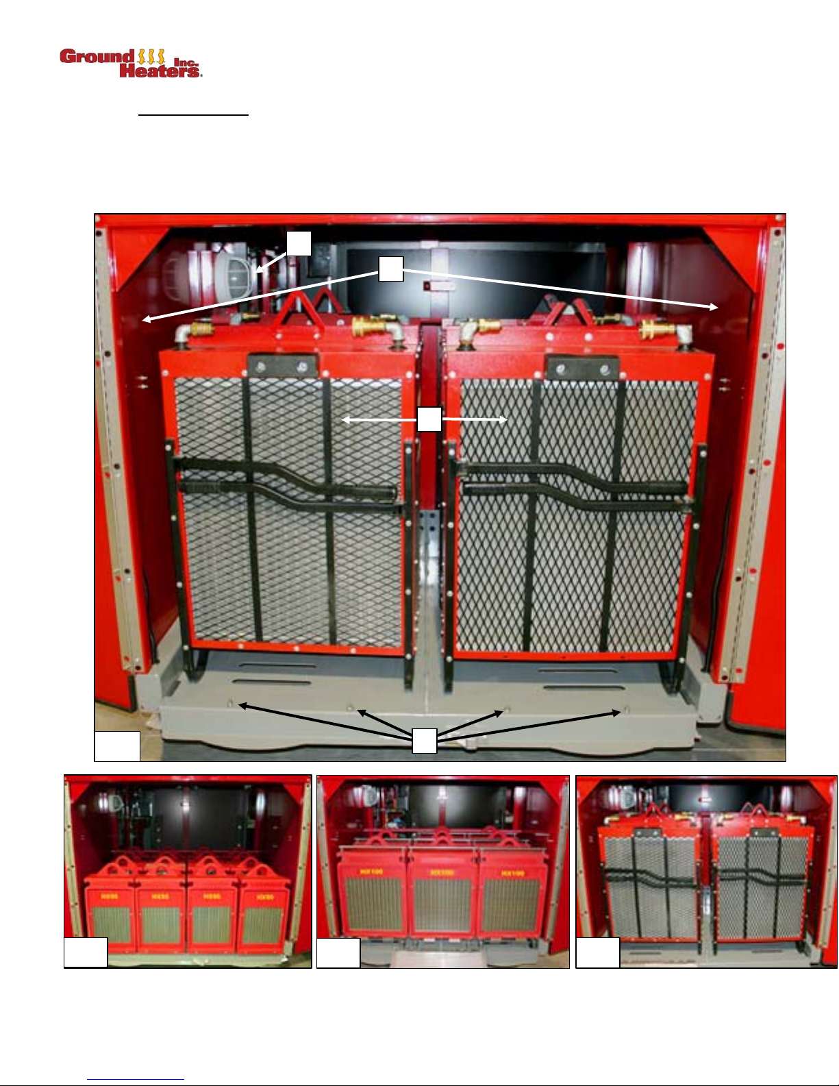
1.2.3 Inside Rear Doors
The following components are located inside the Rear Door: (Photo 1-5 through 1-8)
1. HX200 Heat Xchangers
2. Cab Interior Light and Remote Manifold Storage Location – not shown)
3. Ramp Alignment Pins
4. Ramp Storage and Remote Manifold Storage (not shown)
2
TM
4
1
1-5
1-6
HX50 (LOADED)
V. 2, Rev. 09/01/06 © 2006 Ground Heaters, Inc. 1- 5
1-7
3
HX100 (LOADED)
1-8
HX200 (LOADED)
Page 20

PUREHEAT™ HYDRONIC AIR HEATER OPERATOR’S MANUAL – SECTION 1
1.3 IDENTIFICATION
The Pureheat™ Hydronic Air Heater serial number is located on the Main Control Panel. Always
reference the Pureheat serial number when ordering parts or requesting technical assistance.
1.4 SAFETY FEATURES
Pureheat™ Hydronic Air Heaters are safe, quality equipment, are NHTSA
requirements, meet all Transport
Specific safety features include:
1. Trailer Brakes
2. Hydronic Heater
3. Low Level Shutdown Device
minimum operating level. Manual reset requirement prevents unsupervised Pump/Burner start up.
4. Ground Fault Interrupters (GFI)
5. Circuit Overload Protection
6. Burner Flame Monitoring
ignite or upon loss of flame. Manual reset requirement prevents unsupervised restart.
7. Pump Motor Overload Protection
8. Burner Motor Overload Protection
Motor only) and internal thermal overload trip with automatic reset (NG/LP only).
9. Reflective Markers
10. Foot Pedal
from shock hazard should the Foot Pedal become accidentally immersed in water.
11. Digital Temperature Control
malfunction
: electric with breakaway switch (12 VDC).
: for Hose Rewind system wired with low voltage (12 VDC) signal to protect personnel
compliant, meet all state
Canada requirements, and are CSA certified.
: operates at zero (atmospheric) pressure.
: turns off the Burner and Pumps if HTF level in the system drops below
: built into control panel to protect all circuits.
: built into Main Control Panel to protect all circuits and components.
: Burner Control uses optic flame sensor to shut off Burner if flame fails to
: internal thermal overload trip with automatic reset.
: internal thermal overload trip with manual reset (diesel Burner
: enhance night identification.
: fails safe (Burner OFF) upon loss of power or temperature sensor
12. System Over Temperature Backup Shutdown
Motor should HTF temperature exceed 200°F.
13. Natural Gas (NG) / Propane (LP) Burner
a. Ten (10) Second Pre-Purge Timer
b. Automatic Burner Sequencing
c. Flame Monitoring
d. System Status Indication
e. System / Self-Diagnostics
f. Post-Purge Timer
g. Pilot Valve / Ignition
h. Infrared Flame Detector
i. Air Flow Proving Switch
1.5 SAFETY PRECAUTIONS
Ground Heaters, Inc. develops and manufactures equipment that is safe to operate. However, an
accident could occur if
instructions and precautions be followed. Key safety precautions are posted on decals throughout
that all
the machine. Read and understand all material in this Operator’s Manual and on the decals posted on
Pureheat before attempting to operate it.
the
the Pureheat™ Hydronic Air Heater is used improperly. Safe operation requires
: Bi-metal snap disc will shut down the Burner Blower
:
1- 6 © 2006 Ground Heaters, Inc. V. 2, Rev. 09/01/06
Page 21

PUREHEAT™ HYDRONIC AIR HEATER OPERATOR’S MANUAL – SECTION 1
1.5.1 Burner Setup, Installation and Adjustment Requirements
Licensed gas technician required. NG/LP Burner setup and installation, fuel supply connection, test firing and
Burner adjustment must
requirements of all relevant local, state, provincial and federal authorities. The licensed gas technician must
use Two (2) Manometers to properly adjust supply and manifold gas pressure. A Combustion Analyzer and
Smoke Spot Tester must
parameters (O
, Exhaust temperature and smoke) have been achieved. The licensed gas technician must
2
supply all fuel lines, fittings, regulators, etc. necessary to connect the
at the correct pressure and volume.
be performed by a licensed professional gas technician and must conform to the
be used to properly adjust Burner emissions and verify that proper combustion
Pureheat NG/LP Burner to the fuel source
NOTE: In
the Commonwealth of Massachusetts, gas piping shall be installed by a licensed plumber or
fitter.
gas
Diesel Burner setup, installation and adjustment must
Diesel Burner technician. The Diesel Burner technician must use a Fuel Pressure Test Gauge to properly
adjust the fuel pressure. A Combustion Analyzer and a Smoke Spot Tester must
adjust Burner emissions and to verify that proper combustion parameters (O
smoke) have been achieved.
1.5.2 Operators
There are no published standards or certification requirements for operating portable hydronic heating
machines. The following criteria reflect the experience of Ground Heaters, Inc. and should be considered
a guide, not a comprehensive requirement. The following operator
facilitate satisfactory results, and ensure reliable service from the Pureheat™ Hydronic Air Heater.
1. Patience
: Insures the system runs at optimum levels; leaks are found and fixed; valves are properly
set; and switches are activated properly.
2. Good Hearing, Vision and Smell
: Enables operator to assess equipment and detect potential
malfunctions.
3. Self Respect
with personal safety. Do
substances
4. Careful and Responsible
: Dresses for the weather; wears eye protection and gloves; and does not take chances
not operate the Pureheat while intoxicated or impaired by alcohol or other
.
: Insures the machine is operating properly before leaving it unattended;
keeps track of fluid levels; locks compartments; conducts operational checks at regular intervals; and
ensures proper officials are notified of the machine’s use.
5. Above all, a Pureheat™ Air Heater operator reads and understands this Operator’s Manual and the
decals posted on the machine.
!
Failure to adhere to all
damage to the Pureheat™ Air Heater™, damage to other property, personal injury, or
possibly death.
safety precautions and recommendations may result in
be performed by a trained and knowledgeable
be used to properly
, Exhaust temperature and
2
characteristics will prevent accidents,
1.5.3 Safe Operation and Maintenance
1. Read and understand all material in this Operator’s Manual and on the decals posted on the
Pureheat
™ Air Heater before attempting to operate it.
2. Keep unauthorized people, especially children, away from the
3. Keep guards in place. Do not disable safety features.
4. Keep safety and instruction decals clean and legible. Replace damaged decals.
5. Do not operate the Burner while the Pureheat
area. The Burner Exhaust contains carbon monoxide, a colorless, odorless and deadly gas.
6. Locate the
Pureheat on firm/level ground and chock wheels before operating.
7. Do not smoke while refueling. Do not refuel near open flame or sparks.
8. Clean up fuel spills immediately.
V. 2, Rev. 09/01/06 © 2006 Ground Heaters, Inc. 1- 7
Pureheat.
™ Hydronic Air Heater is in an enclosed, non-ventilated
Page 22

PUREHEAT™ HYDRONIC AIR HEATER OPERATOR’S MANUAL – SECTION 1
9. Do not transport people in or on the Pureheat
™ Hydronic Air Heater.
10. If the
11. Always wear gloves when handling hot or cold components—especially the Circulation Hose. Never
12. Do not attempt tire repairs. Have a qualified tire dealer or repair service perform required tire
13. Torque for wheel lug nuts should be set at 110 ft-lbs.
1.6 REPAIR PARTS AND ACCESSORIES
Your Ground Heaters Distributor carries a complete line of parts and accessories needed for all repair or
replacement requirements.
1.7 MAINTENANCE
All maintenance should be performed by a qualified service technician using the Operators Manual.
The following preventative maintenance should be performed once per year or every 1,500 hours,
whichever comes first:
Pureheat starts to function improperly, turn OFF immediately and repair before restarting.
loosen or remove Circulation Hoses while a Pump or Burner is running or when the HTF temperature
is above 120ºF (49°C).
maintenance.
Failure to observe these warnings may result in injury or death.
!
• Hydronic Heater and Burner cleaning and inspection (Refer to section 3 of the Service Manual.)
• Low Level Shutdown Device operation verification (Refer to Appendix A-18, Pureheat Safety
Controls Low Level Shutdown Device).
• Temperature Control accuracy and operation verification (refer to section 2.1.5 of the Service
Manual).
• Routine Trailer Axle maintenance (common mechanical experience).
1.8 OBTAINING WARRANTY SERVICE
Your satisfaction is important to your Ground Heaters Distributor as well as to Ground Heaters, Inc.
Warranty details are explained in the Ground Heaters, Inc. Statement of Warranty found on the reverse
side of the Customer Delivery Checklist.
All warranty services must be completed by a certified Ground Heaters Distributor service technician. If
your Distributor does not satisfactorily resolve the problem, please call Ground Heaters, Inc. at
877-799-960
• Name, address and phone number
• Machine serial number
• Date of purchase
• Distributor name and address (location)
• Nature of problem
Thank you for purchasing a Pureheat™ Hydronic Air Heater. Both your Ground Heaters Distributor and
Ground Heaters, Inc. want to assist you in every way possible to ensure your complete satisfaction with
your purchase.
0 for assistance. You
will need to provide the following information for assistance:
1- 8 © 2006 Ground Heaters, Inc. V. 2, Rev. 09/01/06
Page 23

PUREHEAT™ HYDRONIC AIR HEATER OPERATOR’S MANUAL–SECTION 2
START UP, OPERATION AND SHUTDOWN
2.1 CIRCULATION SYSTEM ADVISORY
2.1.1 Standard Configuration Performance
2.1.1.1 HX200 Heat Xchangers™
A Pureheat™ Hydronic Air Heater equipped with HX200 Heat Xchangers
following system configurations:
• Connection of up to Four (4) HX200 Heat Xchangers
TM
utilizing any combination [50 ft (15 m),
100 ft (30 m) or 200 ft (61 m)] of Circulation Hoses. Maximum run should not exceed 200 ft (61
m) from base unit.
• The maximum vertical rise or drop from the Pureheat to each HX200 is 60 ft (18 m) one way from
base unit.
2.1.1.2 HX200 Heat Xchangers™ with Optional Booster Pump
A Pureheat™ Hydronic Air Heater equipped with HX200 Heat Xchangers™, optional Booster Pump and
Auxiliary Pump Panel should conform to the following system configurations:
• Connection of up to Four (4) HX200 Heat Xchangers
TM
utilizing any combination [50 ft (15 m),
100 ft (30 m) or 200 ft (61 m)] of Circulation Hoses with a maximum overall horizontal run not to
exceed 400 ft (122 m) from base unit.
• The maximum vertical rise or drop from the Pureheat to each HX200 is 100 ft (30 m) one way
from base unit.
2.1.1.3 HX100 Heat Xchangers™
A Pureheat™ Air Heater equipped with HX100 Heat Xchangers
TM
and 4-Port Remote Manifolds should
conform to the following system configurations:
TM
should conform to the
• Connect the Four (4) 4-Port Remote Manifolds utilizing any combination [50 ft (15 m) or 100 ft (30
m)] of Circulation Hoses with a maximum overall horizontal run not to exceed 150 ft (45 m) for
each 4-Port Remote Manifold.
TM
• The maximum vertical rise or drop from the Pureheat to each Xchanger
or 4-Port Remote
Manifold is 60 ft (18 m) one way from base unit.
• Connect Two (2) HX100 Heat Xchangers
utilizing the 40 ft (12 m) 5/8 in. ID Black Circulation Hoses mounted on the HX100 Heat
Xchangers
TM
.
2.1.1.4 HX100 Heat Xchangers™ with Booster Pump
TM
to each of the Four (4) 4-Port Remote Manifolds
A Pureheat™ Hydronic Air Heater equipped with the HX100 Heat Xchangers™, 4-Port Remote
Manifolds, optional Booster Pump and Auxiliary Pump Panel should conform to the following system
configurations:
• Connect the Four (4) 4-Port Remote Manifolds utilizing any combination [50 ft (15 m), 100 ft (30
m) or 200 ft (61 m)] of Circulation Hoses with a maximum overall horizontal run not to exceed 350
ft (106 m) for each 4-Port Remote Manifold.
• The maximum vertical rise or drop from the Pureheat to each Xchanger or 4-Port Remote
Manifold is 100 ft (30 m) one way from base unit.
• Connect Two (2) HX100 Heat Xchangers
utilizing the 40 ft (12 m) 5/8 in. ID Black Circulation Hoses mounted on the HX100 Heat
Xchangers
TM
.
TM
to each of the Four (4) 4-Port Remote Manifolds
V. 2, Rev. 09/01/06 © 2006 Ground Heaters, Inc. 2- 1
Page 24

PUREHEAT™ HYDRONIC AIR HEATER OPERATOR’S MANUAL – SECTION 2
2.1.1.5 HX50 Heat Xchangers™
A Pureheat™ Hydronic Air Heater equipped with HX50 Heat Xchangers
should conform to the following system configurations:
• Connect the Four (4) 4-Port Remote Manifolds utilizing any combination [50 ft (15 m) or 100
ft (30 m)] of Circulation Hoses with a maximum overall horizontal run not to exceed 150 ft
(45 m) for each 4-Port Remote Manifold.
• The maximum vertical rise or drop from the Pureheat to each Xchanger
Manifolds is 60 ft one way from base unit.
• Connect Four (4) HX50 Heat Xchangers
Manifolds utilizing the 40 ft (12 m) 1/2 in. ID Black Circulation Hoses mounted on the
HX50 Heat Xchangers
TM
and 4-Port Remote Manifolds
TM
or 4-Port Remote
TM
to each of the Four (4) 4-Port Remote
TM
.
2.1.1.6 HX50 Heat Xchangers™ with Booster Pump
A Pureheat™ Air Heater equipped with the HX50 Heat Xchangers™, 4-Port Remote Manifolds, optional
Booster Pump and Auxiliary Pump Panel should conform to the following system configurations:
• Connect the Four (4) 4-Port Remote Manifolds utilizing any combination [50 ft (15 m), 100 ft
(30 m) or 200 ft (61 m)] of Circulation Hoses with a maximum overall horizontal run not to
exceed 350 ft (106 m) for each 4-Port Remote Manifold.
• The maximum vertical rise or drop from the Pureheat to each Xchanger
TM
or 4-Port Remote
Manifold is 100 ft (30 m) one way from base unit.
• Connect the Four (4) HX50 Heat Xchangers
Manifolds utilizing the 40 ft (12 m) 1/2 in. ID Black Circulation Hoses mounted on the
HX50 Heat Xchangers
2.1.1.7 Maximum Heat Xchanger™ Connection Capability
TM
.
Connecting the maximum number of Heat Xchangers™ will
TM
to each of the Four (4) 4-Port Remote
not increase the heat delivered to the space
(compared to above stated standard configurations) but will provide increased air circulation.
All Pureheat™ Hydronic Air Heaters are equipped with a 5-Port On-Board Manifold (Circulation Hoses
connection points) capable of a maximum connection of five (5) HX200 Heat Xchangers™, ten (10)
HX100 Heat Xchangers™ with Five (5) 4-Port Remote Manifolds, and twenty (20) HX50 Heat
Xchangers™ with Five (5) 4-Port Remote Manifolds.
2.1.2 Optional Booster Pump
All Pureheat™ Hydronic Air Heaters are equipped to accept an optional Booster Pump which requires the
use of an Auxiliary Pump Panel for electrical connection to provide safety shutdown of the optional
Booster Pump. (For setup instructions, refer to Section 2.8, CONNECTING/DISCONNECTING
OPTIONAL BOOSTER PUMP.)
2.1.3 Circulation Hose Limitations
Do not
create excessively long Circulation Hoses by connecting multiple (more than two) Circulation
Hoses in series. Multiple QCs cause a loss of working pressure and restrict flow.
• Regardless of length, no more than two (2) Supply Circulation Hoses should be connected in
series;
• Regardless of length, no more than two (2) Return Circulation Hoses should be connected in
series;
• Overall Supply and
Return Circulation Hoses should be no more than a combined 400 ft (122 m)
in length (with Main Pump);
• Overall Supply and
Return Circulation Hoses should be no more than a combined 800 ft (244 m)
in length (with optional Booster Pump);
2- 2 © 2006 Ground Heaters, Inc. V. 2, Rev. 09/01/06
Page 25
PUREHEAT™ HYDRONIC AIR HEATER OPERATOR’S MANUAL–SECTION 2
!
2.1.4 Insulate Circulation Hoses
Any Circulation Hoses exposed to the outdoor elements should be insulated for maximum heat delivery
into work space. Ground Heaters, Inc. recommends wrapping a cut-to-size Red Wave™ Blanket around
exposed Circulation Hoses. Secure the wrapped blankets to minimize air infiltration and heat loss.
Contact your local Ground Heaters Distributor for additional system configuration advice.
2.1.5 Circulation Hose Protection
Do not drive any vehicles or equipment over the Circulation Hoses. If the Hoses must be deployed in
high traffic areas, construct ramps or guards to protect from damage.
HTF may discolor floor surface. Provide extra protection and care to circulation
hoses when floor appearance is critical. Place hoses away from high traffic areas
whenever possible.
2.2 PRE-START UP CHECKS
2.2.1 Positioning
1. Position the Pureheat’s 5-Port On-Board Manifold as close as possible to the space to be heated.
Circulation Hoses can then easily enter and exit the structure.
!
2. Chock the wheels to prevent accidental rolling.
The Pureheat must be positioned a minimum of 12 ft (3.6 m) from fuel source or
combustible materials.
3. Use the Heavy Duty Jack-Stand to position the machine as level as possible.
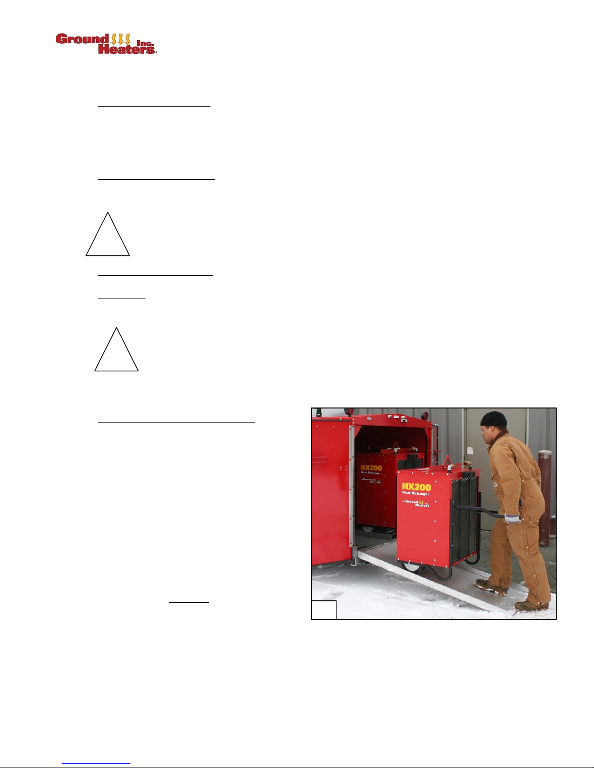
2.2.2 Unloading HX200 Heat Xchangers
1. OPEN the Rear Doors and remove the
aluminum Ramp from its storage location
above Xchangers
2. Position the Ramp onto the Ramp
Alignment Pins to unload either the left side
or the right side HX200s. (Photo 2-1)
NOTE: Each HX200 Heat Xchanger
with wheels and fold-out handles.
3. Position the HX200s inside the building per
your heating plan. (Refer to Appendix C-1,
Pureheat APPLICATION LAYOUTS.)
NOTE: Each HX200 Heat Xchanger
connected to a separate
AC 60 Hz electrical circuit. Use 12-3
extension cords of no more than 100 ft (30
m) in length.
4. Momentarily turn the BLOWER Switch ON to test Blower operation then turn the BLOWER Switch
OFF.
TM
.
TM
TM
must be
15 amp. 120 volts
TM
is equipped
2-1
V. 2, Rev. 09/01/06 © 2006 Ground Heaters, Inc. 2- 3
Page 26
PUREHEAT™ HYDRONIC AIR HEATER OPERATOR’S MANUAL – SECTION 2
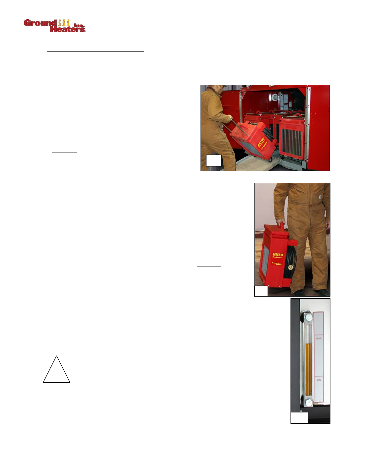
2.2.3 Unloading HX100 Heat XchangersTM
1. OPEN the Rear Doors and remove the aluminum Ramp from the storage location above Xchangers.
2. Position the Ramp onto the Ramp Alignment Pins to unload either the left side, right side or the
middle section HX100s. (Photo 2-2)
NOTE: Each HX100 Heat Xchanger
wheels, Lifting Bail and Lift-Up Handle.
3. Position the HX100s inside the building per your
heating plan. (Refer to Appendix C-1, PUREHEAT
APPLICATION LAYOUTS.)
NOTE: Each HX100 Heat Xchanger
a separate
circuit. Use 12-3 gauge extension cords of no more
than 100 ft (30 m) in length.
4. Momentarily turn the Fan Switch ON to test Fan operation then turn the Fan Switch OFF.
2.2.4 Unloading HX50 Heat Xchangers
1. OPEN the Rear Doors and unload the HX50s. (Photo 2-3)
NOTE: Each HX50 Heat Xchanger
Handles. The HX50 Heat Xchangers
can be lifted by one individual.
2. Position the HX50s inside the building per your heating plan. (Refer to
Appendix C-1, PUREHEAT APPLICATION LAYOUTS.)
NOTE: Each HX50 Heat Xchanger
120 volts AC 60 Hz electrical circuit. Use 12-3 gauge extension cords
of no more than 100 ft (30 m) in length.
15 amp. 120 volts AC 60 Hz electrical
TM
TM
TM
must be connected to a separate 15 amp.
TM
is equipped with
must be connected to
2-2
TM
is equipped with a Lifting Bail and
TM
weigh approximately 70 lbs and
3. Momentarily turn the Fan Switch ON to test Fan operation then turn the
Fan Switch OFF.
2.2.5 Heat Transfer Fluid (HTF)
OPEN the Side Doors and Latch them to the Door Tiebacks
1. Verify Heat Transfer Fluid (HTF) level is between MIN and MAX lines on the Sight
Gauge Decal located on expansion tank above Hydronic Heater. (Photo 2-4) If fluid
level is not above MIN level, refer to Section 4.1, ADDING HEAT TRANSFER FLUID,
to correct before attempting to start the Burner or HTF Pump.
If HTF temperatures are below -15ºF (-26ºC), pre-heat the HTF and
!
2.2.6 Switch Positions
(Refer to Appendix A-2.)
Verify the MAIN BREAKER 1, MAIN BREAKER 2, PUMP, BURNER, CAB LIGHT and
HOSE REWIND Switches are in the OFF position on the Main Control Panel.
Pump housing before turning the Pump ON.
2-3
2-4
2- 4 © 2006 Ground Heaters, Inc. V. 2, Rev. 09/01/06
Page 27
PUREHEAT™ HYDRONIC AIR HEATER OPERATOR’S MANUAL–SECTION 2
2.2.7 Deployment of Circulation Hoses or Option Heat Transfer Hose
(Applies to Pureheat and Hose Handling Systems HHS3004)
The Hose Reel contains Ten (10) 1 in. ID Red Circulation Hoses with QCs [Four (4) at 50 ft (15 m), Four
(4) at 100 ft (30 m), and Two (2) at 200 ft (61 m)].
1. Release the Hose Reel Brake by turning the Brake T-handle counterclockwise
2. Remove the 1 in. ID Red Circulation Hoses with QCs or 5/8 in. ID Black Heat Transfer Hose Loops
(HHS3004) from the Hose Reel. Disconnect each hose Quick-Connect as it is removed from the
Hose Reel.
3. Select the shortest
return connection to each Heat Xchanger
1 in. ID Red Circulation Hoses and route, one at a time, to provide a supply and
TM
or 4-Port Remote Manifold (if applicable) and 5-Port On-
Board Manifold.
4. Connect Circulation Hoses to the respective Heat Xchanger
applicable) Supply and Return connections.
Support the QC on the HX200 Xchanger
TM
with
one hand when making these connections to
insure good connection. Ensure hoses lay on top
of HX200 Heat Xchanger
TM
once connection is
made to avoid HTF restrictions.
5. The HX50 and the HX100 series Heat
Xchangers
TM
are equipped with 40 ft (12 m) of ½ in
or 5/8 in. ID Black Circulation Hoses permanently
mounted and will connect to the 4-Port Remote
Manifolds. Four (4) HX50 or Two (2) HX100 can be
connected per 4-Port Remote Manifold).
TM
or 4-Port Remote Manifold (if
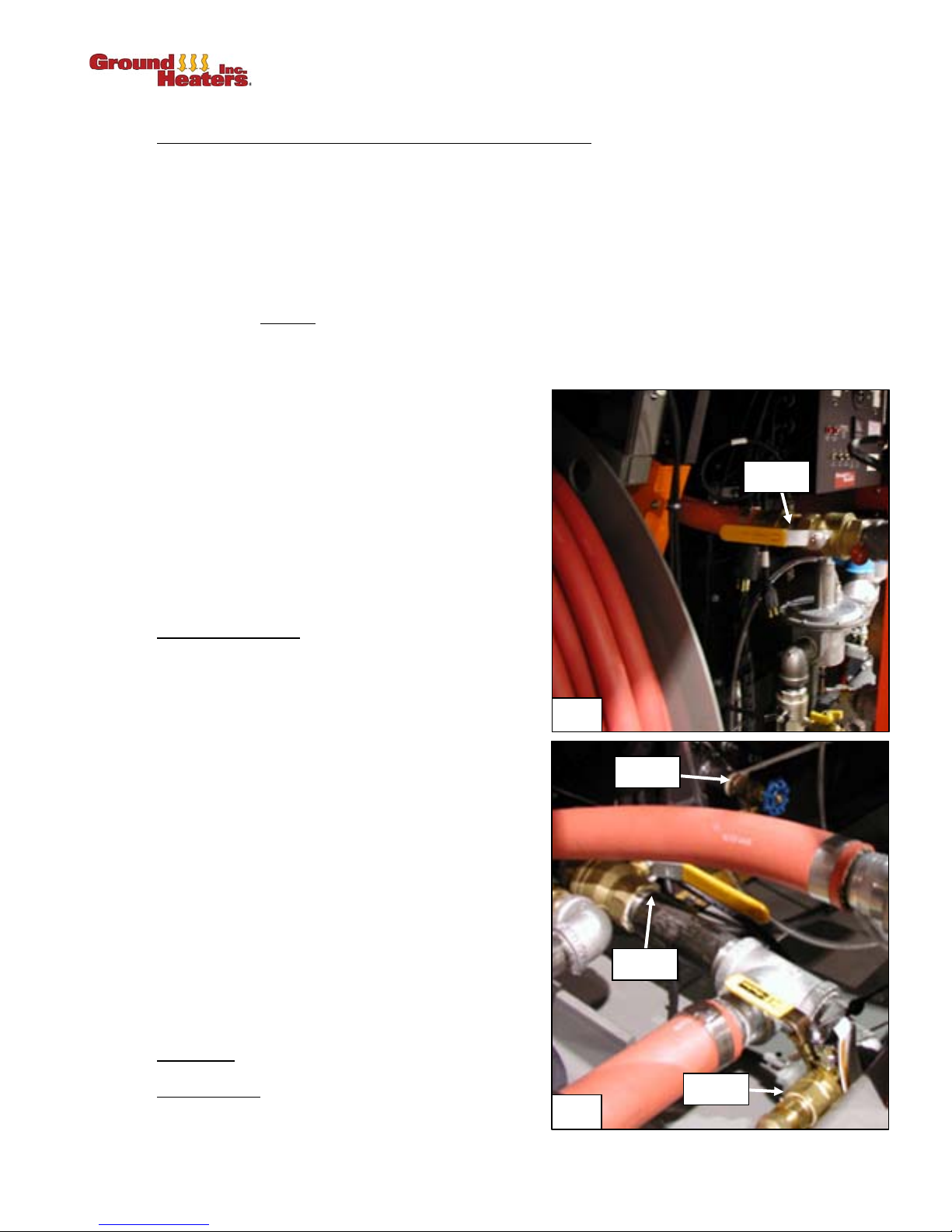
Valve #2
2.3 INITIAL POWER UP
1. Connect the Main Control Panel Pigtail marked
MAIN POWER 1 to an extension cord connected
to one 15 amp 120 volts AC 60 Hz electrical power
circuit. Connect the Main Control Panel Pigtail
marked MAIN POWER 2 Twist-Lock Male cord
end to a Twist-Lock Female cord end extension
cord connected to one 20 amp 120 volts AC 60 Hz
electrical power circuit. Use only heavy-duty 10-3
extension cords of no more than 100 ft (30 m) in
length.
2. Turn the MAIN BREAKER 1 and MAIN BREAKER
2 Switches ON, verify the following:
a. LINE 1 and 2 GFI’s remain reset and Amber
Indicator Lights are OFF.
b. LOW LEVEL FAULT light is ON for fifteen
seconds and then turns OFF.
c. Temperature Control (TC) displays HTF
temperature in red and desired temperature
(set point) in green numbers.
2.4 START UP
2-5
Valve #1
Valve #3
2.4.1 Integrity Check
Verify all hose, fittings, and pipe connections are not
leaking.
V. 2, Rev. 09/01/06 © 2006 Ground Heaters, Inc. 2- 5
Valve #4
2-6
Page 28
PUREHEAT™ HYDRONIC AIR HEATER OPERATOR’S MANUAL – SECTION 2
2.4.2 Warming the Heat Transfer Fluid
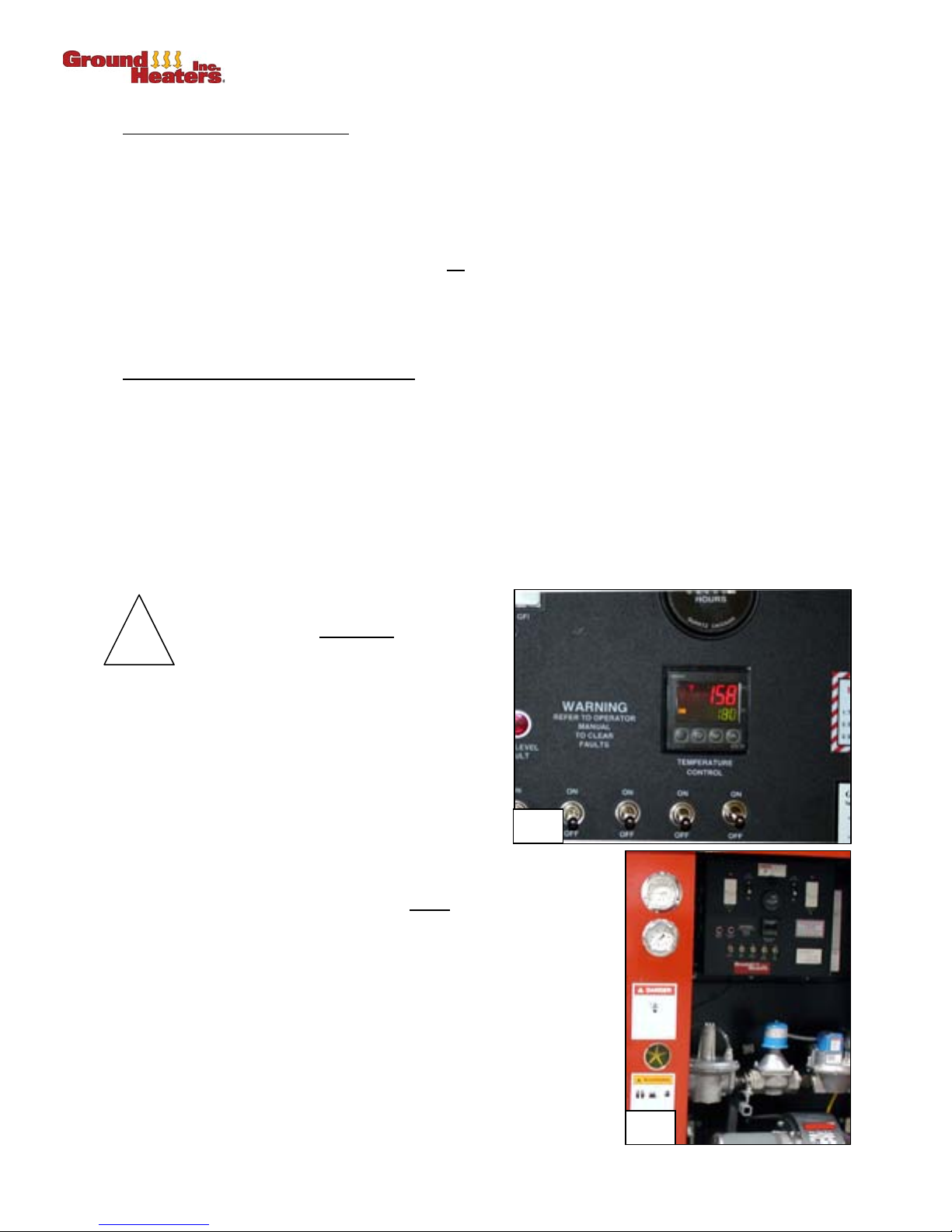
1. Use the UP/DOWN arrow keys to adjust the temperature set-point on the TC to 70°F (21°C). (Refer to
Appendixes A-2 and A-3.)
2. Turn the BURNER Switch ON, then verify the following:
a. The Burner Motor starts (after a five second delay) and fires fifteen seconds later. If the Burner
fails to start, refer to Appendixes A-12 and A-13.
b. The Burner runs clean, quiet and with no
qualified service technician should check Burner settings and emissions.
NOTE: Section 4.3, BURNER COMBUSTION VERIFICATION AND ADJUSTMENT, provides detailed
instructions for testing Burner emissions and settings.
visible smoke. If the Burner operation is in question, a
2.4.3 Initiating Flow through Heat Transfer Hose
(Refer to Appendix B-1.)
1. Position the following valves as directed below:
a. OPEN the Suction Valve #3. (Photo 2-6)
b. Verify Cross-Connect Valve #5 is OPEN. (Photo 2-13)
c. Verify Return Valve #2 is fully CLOSED. (Photo 2-5)
2. Turn the PUMP Switch ON at the Main Control Panel until the Pump Motor has reached full RPM. The
Dashboard Pressure Gauge will read an approximate 50 psig. Slowly OPEN Return Valve #2, lowering
operating pressure, to a minimum of 30 psig on the Dashboard Pressure Gauge for optimum flow rate.
(Photo 2-8)
If ambient temperatures are below 15ºF (-26ºC), you must
!
3. Turn each Heat Xchanger™ BLOWER or FAN
Switch ON and verify the thermostat is at the
desired set point temperature. Output air
temperature will increase as the system warms
up.
NOTE: Blowers will not run if the Heat Xchanger™
thermostats are set too low.
4. Periodically verify proper system operation using
the dashboard gauges. Adjust Return Valve #2 so that the
Dashboard Pressure Gauge maintains 30 psig. Min. The Return
Flow Indicator should spin. The HTF return
read approximately 40º to 50ºF (22º to 28ºC) less than the supply
temperature (red numbers on the Main Control Panel). (Photo 2-7
and 2-8)
Pump before turning the Pump ON.
pre-heat the
2-7
temperature should
5. Set the TC to temperature required for application.
NOTE: Always set the TC to 180°F (82°C) for thawing, frost prevention
and air heating applications. Concrete curing applications
usually require temperature settings below 180ºF (82ºC).
2- 6 © 2006 Ground Heaters, Inc. V. 2, Rev. 09/01/06
2-8
Page 29

PUREHEAT™ HYDRONIC AIR HEATER OPERATOR’S MANUAL–SECTION 2
2.5 OPERATING WITH OPTIONAL ACCESSORIES
The Pureheat has the capability to operate with up to Twenty (20) 750 ft (228 m) Accessory Hose Loops
using One (1) Booster Pump, Five (5) Hose Handling Systems 3004 (HHS3004), Five (5) 4-Port Remote
Manifolds and One (1) Auxiliary Pump Panel.
2.5.1 Using Three HHS3004 with Booster Pump for Thawing Applications
(Refer to Appendix B-6.)
Thawing applications require the use of Three (3) HHS3004s with Twelve (12) 750 ft (228 m) Accessory
Hose Loops of 5/8 in. ID Heat Transfer Hose (HTH), One (1) optional Booster Pump, Three (3) 4-Port
Remote Manifolds and One (1) Auxiliary Pump Panel.
1. Install the optional Booster Pump and Auxiliary Pump Panel as directed in Section 2.8,
CONNECTING/DISCONNECTING OPTIONAL BOOSTER PUMP.
2. Place the Three (3) HHS3004s and Three (3) 4-Port Remote Manifolds spaced appropriately on the
jobsite for thawing application.
3. Connect the Three (3) 4-Port Remote Manifolds to the 5-Port On-Board Manifold as directed in Step
2.2.7, Deployment of Circulation Hoses.
4. Connect the Accessory Hose Loop 1 Female QC to one of the available 4-Port Remote Manifold
Discharge Male QCs.
5. Remove the Accessory Hose Loop 1 from the HHS3004 Reel and place at job site for thawing
application. The QCs joining Accessory Hose Loop 1 and Accessory Hose Loop 2 will be exposed
when nearing the end of Accessory Hose Loop 1.
6. Once the QCs have been exposed, separate Accessory Hose Loop 1 and Accessory Hose Loop 2.
Connect the Accessory Hose Loop 1 Male QC to one of the available 4-Port Remote Manifold Return
Female QCs.
7. Connect the Accessory Hose Loop 2 Female QC to one of the remaining 4-Port Remote Manifold
Discharge Male QCs.
8. Remove the Accessory Hose Loop 2 from the HHS Reel and place at job site for thawing application.
The QCs joining Accessory Hose Loop 2 and Accessory Hose Loop 3 will be exposed when nearing
the end of Accessory Hose Loop 2.
9. Once the QCs have been exposed, separate Accessory Hose Loop 2 and Accessory Hose Loop 3
QCs. Connect the Accessory Hose Loop 2 Male QC to one of the available 4-Port Remote Manifold
Return Female QCs.
10. Repeat Step 4 through Step 9 for the remaining Accessory Hose Loop 3 and Accessory Hose Loop 4
of the HHS3004.
11. Repeat Step 4 through Step 10 for the remaining Two (2) HHS3004s.
12. Power up the Main Control Panel as directed in Section 2.3, INITIAL POWER UP and start the
optional Booster Pump after starting the Main Pump.
The Booster Pump must
!
2.5.2 Using Five HHS3004 with Booster Pump for Curing and Frost Prevention Applications
(Refer to Appendix B-7 and B-8.)
Curing and Frost Prevention applications require the use of Five (5) HHS3004 with Twenty (20) 750 ft
(228 m) Accessory Hose Loops of 5/8 in. ID Heat Transfer Hose (HTH), One (1) optional Booster Pump,
Five (5) 4-Port Remote Manifolds and One (1) Auxiliary Pump Panel.
1. Install the optional Booster Pump and Auxiliary Pump Panel as directed in Section 2.8,
CONNECTING/DISCONNECTING OPTIONAL BOOSTER PUMP.
HTF level protection. Operating the Booster Pump without low HTF level protection
could lead to complete loss of system HTF and HTF Pump failure.
be connected to the Auxiliary Pump Panel to maintain low
V. 2, Rev. 09/01/06 © 2006 Ground Heaters, Inc. 2- 7
Page 30

PUREHEAT™ HYDRONIC AIR HEATER OPERATOR’S MANUAL – SECTION 2
2. Place the Five (5) HHS3004 and Five (5) 4-Port Remote Manifolds spaced appropriately on the
jobsite for thawing application.
3. Connect the five (5) 4-Port Remote Manifolds to the 5-Port On-Board Manifold as directed in Step
2.2.7, Deployment of Circulation Hoses.
4. Connect the Accessory Hose Loop 1 Female QC to one of the available 4-Port Remote Manifold
Discharge Male QCs.
5. Remove the Accessory Hose Loop 1 from the HHS3004 Reel and place at job site for thawing
application. The QCs joining Accessory Hose Loop 1 and Accessory Hose Loop 2 will be exposed
when nearing the end of Accessory Hose Loop 1.
6. Once the QCs have been exposed, separate Accessory Hose Loop 1 and Accessory Hose Loop 2.
Connect the Accessory Hose Loop 1 Male QC to one of the available 4-Port Remote Manifold Return
Female QCs.
7. Connect the Accessory Hose Loop 2 Female QC to one of the remaining 4-Port Remote Manifold
Discharge Male QCs.
8. Remove the Accessory Hose Loop 2 from the HHS Reel and place at job site for thawing application.
The QCs joining Accessory Hose Loop 2 and Accessory Hose Loop 3 will be exposed when nearing
the end of Accessory Hose Loop 2.
9. Once the QCs have been exposed, separate Accessory Hose Loop 2 and Accessory Hose Loop 3.
Connect the Accessory Hose Loop 2 Male QC to one of the available 4-Port Remote Manifold Return
Female QCs.
10. Repeat Step 4 through Step 9 for the remaining Accessory Hose Loop 3 and Accessory Hose Loop 4
of the HHS3004.
11. Repeat Step 4 through Step 10 for the remaining Four (4) HHS3004s.
12. Power up the Main Control Panel as directed in Section 2.3, INITIAL POWER UP and start the
optional Booster Pump after starting the Main Pump in Step 2.4.3.
The Booster Pump must
HTF level protection. Operating the Booster Pump without low HTF level protection
!
2.6 MONITORING OPERATING PARAMETERS
The following parameters should be monitored regularly:
1. Fuel Tank Level:
2. HTF Level:
3. HTF Return Temperature(s):
surface temperature before rising rapidly to approximately 100ºF (38ºC). Return temperatures will rise
slowly to an approximate 140ºF (60ºC), as the thaw nears completion. During curing applications, the
return temperatures should average 5º to 20ºF (3º to 11ºC) above the concrete surface temperature.
During a frost prevention application, the return temperatures will drop close to the surface
temperature before rising rapidly to approximately 140°F (60°C). During air heating applications, the
return temperatures should be approximately 40ºF (22ºC) below the supply temperature.
could lead to complete loss of system HTF and HTF Pump failure.
Keep track of fuel consumption to plan refueling schedule.
Should remain between MIN and MAX lines on the HTF Sight Gauge Decal. (Photo 2-6)
During a thaw application, the return temperatures will drop close to the
be connected to the Auxiliary Pump Panel to maintain low
4. HTF Supply Pressure:
operating supply pressures should be 30 to 50 psig (207 kPa to 345 kPa).
5. Plumbing and Fitting Leaks
2- 8 © 2006 Ground Heaters, Inc. V. 2, Rev. 09/01/06
During air heat, thawing, curing and frost prevention applications, the
Always check for leaks during each monitoring period.
Page 31
PUREHEAT™ HYDRONIC AIR HEATER OPERATOR’S MANUAL–SECTION 2
2.7 UNIT SHUTDOWN
2.7.1 Burner Shutdown
1. Turn the BURNER Switch OFF and allow system cool down.
2. Continue running the Main Pump and optional Booster Pump (if
applicable) for 15 to 20 minutes to cool the HTF to 120ºF (49ºC) or
lower.
3. Turn the Main PUMP and BOOSTER PUMP (if applicable) Switch
OFF.
4. SHUT the Return Valve #2 and Suction Valve #3.
5. SHUT the Cam-Lock Suction Valve #6 and Cam-Lock Return Valve
#7 and Open Cross-Connect Valve #5 (if applicable).
2.7.2 Disconnecting Hoses from Heat Xchangers™ and
1. Disconnect the Supply and Return Hose Sets from the 5-Port OnBoard Manifold and the Heat Xchangers™ or 4-Port Remote Manifold (if
applicable).
2. HX50 and HX100 series 1/2 in. ID X 40 ft. Black Hose Assemblies with
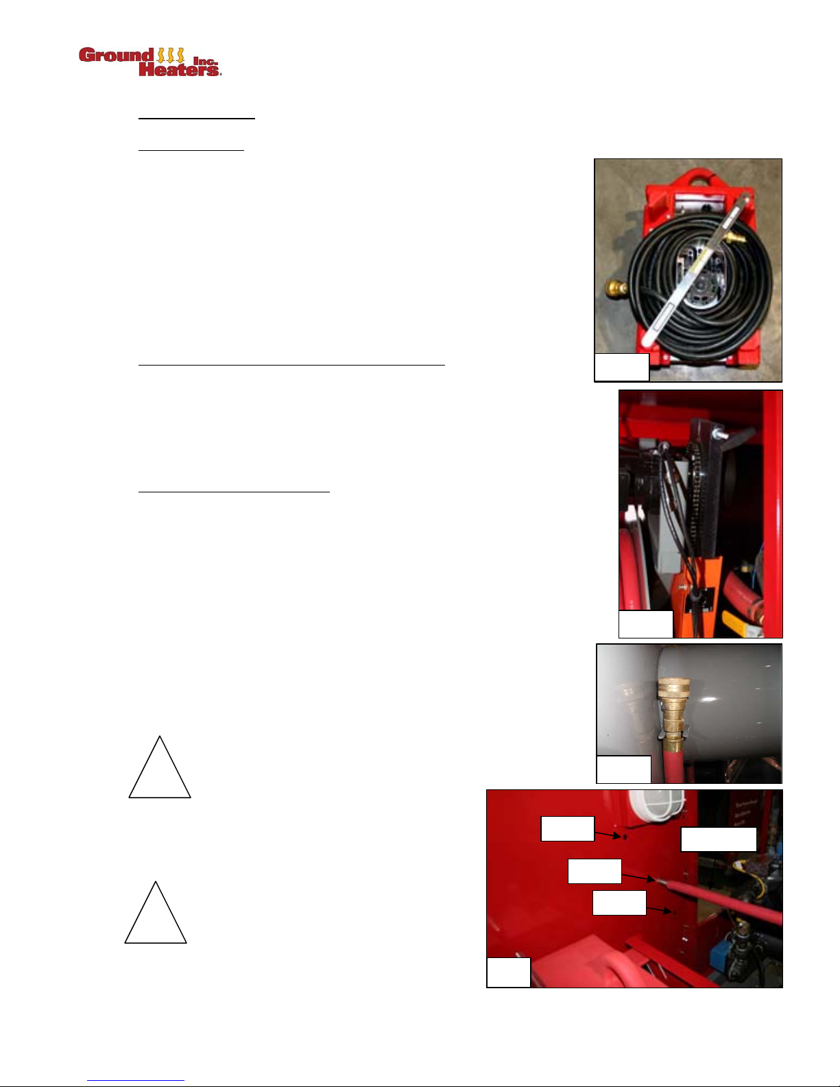
QCs wind onto the back of the Heat Xchanger™. (Photo 2-9)
2.7.3 Rewinding the Circulation Hose
1. Fully release Hose Reel Brake (Photo 2-10) by turning the Brake Thandle counterclockwise. Attach the female end of 200 ft Circulation
Hose to the Hose Reel Rewinding Hook (Photo 2-11). Rewind the
longest hose lengths first.
Pureheat
2-9
2. Turn ON the HOSE REWIND Switch.
3. Rinse QC in a bucket of water to remove any dirt before connecting onto
hose reel. (Refer to Appendix B-11 PUREHEAT SAFTEY CONTROLS
QUICK CONNECT AND CAM-LOCK CARE AND MAINTENANCE.
4. Remove the Foot Pedal from storage location and position to allow
control of rewind operation. The Foot Pedal should be placed on a
piece of plywood or other material to keep it dry.
5. Turn the REWIND MOTOR Switch ON at the Main Control Panel.
Always wear gloves to protect hands while rewinding
!
6. Depress the Foot Pedal to begin rewinding, and
guide the hose evenly onto the Hose Reel.
7. Sequentially connect additional 1 in. ID Red Hose
Assemblies with QC's (200 ft, 100 ft and 50 ft).
!
8. Set the Hose Reel Brake by turning the Brake Thandle clockwise when all of the Supply and
Return Hose Sets have been rewound on the Hose Reel and turn the HOSE REWIND Switch OFF.
circulation hoses.
HX200
HX100
Rewind the final 10 ft (3 m) of each 1 in.
ID Circulation Hose by hand to prevent
damaging a fitting or hose connection.
2-12
2-10
2-11
Support Bar
HX50
V. 2, Rev. 09/01/06 © 2006 Ground Heaters, Inc. 2- 9
Page 32
PUREHEAT™ HYDRONIC AIR HEATER OPERATOR’S MANUAL – SECTION 2
9. Return Foot Pedal to storage location.
2.7.4 Completing Unit Shutdown
1. Retrieve and reload the Heat Xchangers™ into the trailer. Stow ramp, latch and lock the Rear Doors
to secure Heat Xchangers™.
NOTE: If loading a different series of Heat Xchangers™ into the P 1260, refer to Photo 2-12 for proper
positioning of the Heat Xchanger™ Storage Area Cross-Support Bar.
2. Disconnect the optional Booster Pump and Auxiliary Pump Panel as directed in Step 2.8.4.
3. Disconnect fuel supply line(s). NG or LP disconnection requires a qualified technician.
4. Turn the CAB LIGHT, HOSE REWIND, PUMP, BURNER, HTF FILL, MAIN BREAKER 1 and MAIN
BREAKER 2 Switches OFF.
5. Disconnect and remove the power cords; Latch and Lock all remaining Doors.
2.8 CONNECTING/DISCONNECTING OPTIONAL BOOSTER PUMP
(Refer to Appendix A-15 and B-2.)
2.8.1 Connecting
1. Install / connect Auxiliary Pump Panel to the Main Control Panel (Refer to Appendix A-15 and B-2).
NOTE: The Auxiliary Pump Panel ensures that the optional Booster Pump will shutdown if a LOW LEVEL
FAULT condition exists.
2. Place the optional Booster Pump within 6 ft (2 m) of the 5-Port On-Board Manifold.
3. Remove the Suction Cam-Lock Leader Hose, Return Cam-Lock Leader Hose and the Power Cord
stowed in the interior of the Booster Pump enclosure.
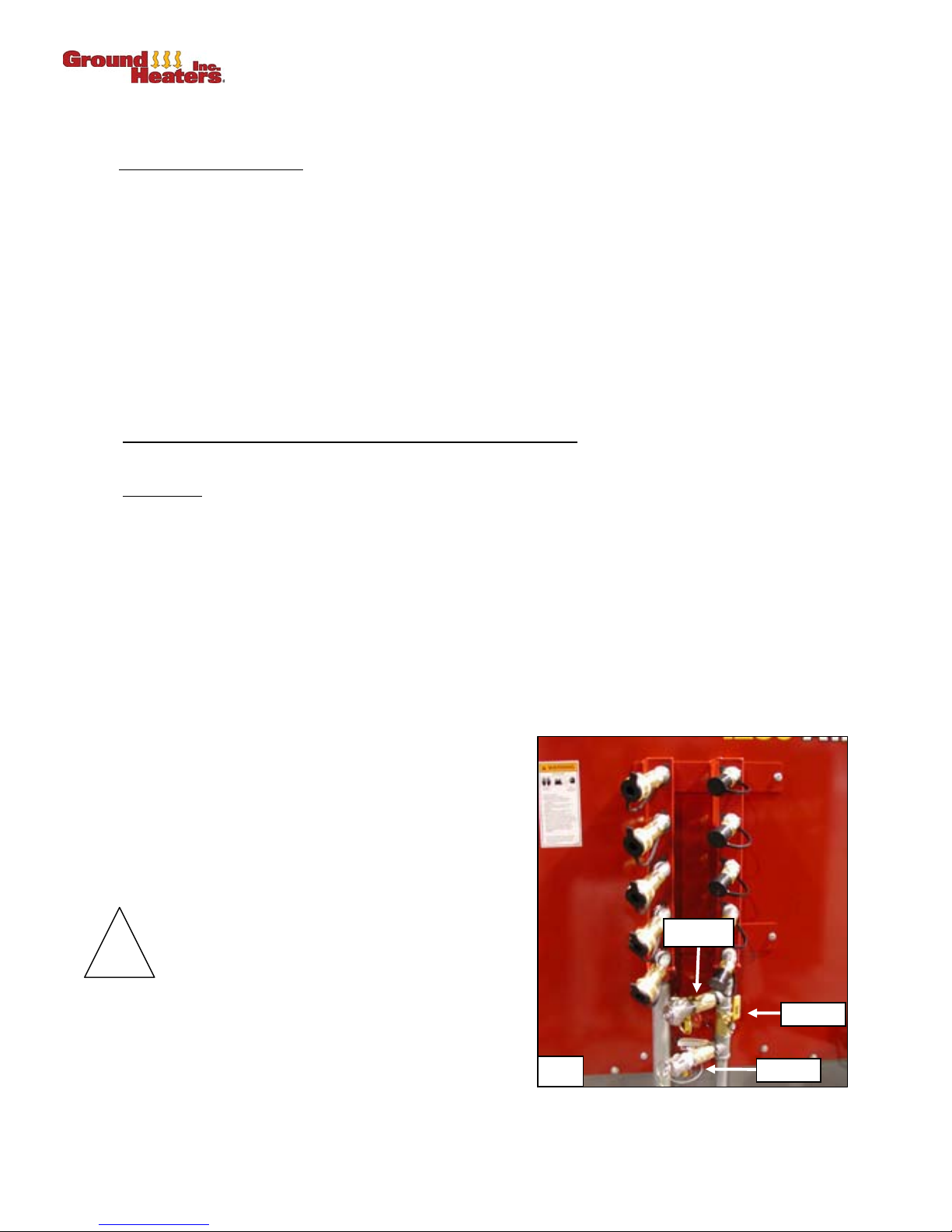
4. Ensure that Suction Valve #6 and Return Valve #7 are SHUT and LOCKED. (Photo 2-13)
5. Ensure the Auxiliary Pump Panel BREAKER Switch is OFF.
6. Ensure the Main PUMP Switch is OFF at the Main
Control Panel.
7. Remove the Protective Caps from the 5-Port OnBoard Manifold and remove the Cam-Lock Protective
Caps of the Cam-Lock Suction Valve #6 and the
Cam-Lock Return Valve #7.
8. Connect the Booster Pump Suction Cam-Lock Leader
Hose to the Cam-Lock Suction Valve #6 Cam-Lock
and connect the optional Booster Pump Return CamLock Leader Hose to the Cam-Lock Return Valve #7.
!
DO NOT CONNECT THE OPTIONAL BOOSTER
PUMP SUCTION LEADER HOSE AND RETURN
LEADER HOSE WITH THE MAIN PUMP ON.
VERIFY SYSTEM PRESSURE IS AT ZERO (0)
PSIG. PRIOR TO CONNECTION.
Valve #7
9. UNLOCK and OPEN Suction Valve #6 and Return
Valve #7. Shut the Cross-Connect Valve #5.
(Photo 2-13)
10. Plug the Booster Pump power cord into the Auxiliary Pump Panel Female Pigtail.
2- 10 © 2006 Ground Heaters, Inc. V. 2, Rev. 09/01/06
2-13
Page 33

PUREHEAT™ HYDRONIC AIR HEATER OPERATOR’S MANUAL–SECTION 2
!
11. Connect a heavy duty 10-3 extension cord of no more than 20 ft (6 m) in length into the Auxiliary
Pump Panel Male Pigtail.
12. Connect a 20 amp. 120 volts AC 60 Hz electrical circuit supply (not the same circuit used for the
Pureheat) to the Auxiliary Pump Panel.
NOTE: The Booster Pump should only be started after the Pureheat has been set up and is ready for use.
The Booster Pump will only operate when the Main PUMP Switch is turned ON at the Main Control
Panel. (Refer to Section 2.4, START UP.)
2.8.2 Start Up
1. Verify Cam-Lock Suction Valve #6 and Cam-Lock Return Valve #7 are in the OPEN position. Verify
2. Turn the BURNER Switch ON at the Main Control Panel.
3. Turn the Main PUMP Switch ON at the Main Control Panel.
4. Turn the Auxiliary Pump Panel BREAKER Switch ON.
2.8.3. Shutdown
1. Turn the BURNER Switch OFF.
2. Continue to operate the Main Pump and optional Booster Pump until the HTF has cooled below
3. Turn the Main PUMP Switch OFF at the Main Control Panel.
4. Turn the Auxiliary Pump Panel BREAKER Switch OFF.
5. SHUT and LOCK Cam-Lock Suction Valve #6 and Cam-Lock Return Valve #7 and replace the Cam-
2.8.4 Disconnecting
1. Disconnect the optional Booster Pump Suction Cam-Lock Leader Hose from the Cam-Lock Suction
2. Disconnect the optional Booster Pump Return Cam-Lock Leader Hose from the Cam-Lock Return
3. Connect the Protective Cap on the optional Booster Pump Suction Cam-Lock Leader Hose and
4. Disconnect the Booster Pump Power Cord and extension cord. Stow the Booster Pump Power Cord,
Cross-Connect Valve #5 is in the SHUT position. (Photo 2-13).
120ºF (49ºC).
Lock Protective Caps. OPEN Cross-Connect Valve #5. (Photo 2-13)
DO NOT DISCONNECT THE OPTIONAL BOOSTER PUMP SUCTION LEADER HOSE AND
RETURN LEADER HOSE UNTIL HTF HAS SUFFICIENTLY COOLED AND SYSTEM
PRESSURE IS AT ZERO (0) PSIG.
Valve #6 and connect the Protective Cap at the 5-Port On-Board Manifold.
Valve #7 and connect the Protective Cap at the 5-Port On-Board Manifold.
Return Cam-Lock Leader Hose.
Suction Cam-Lock Leader Hose and Return Cam-Lock Leader Hose neatly in the Booster Pump
enclosure.
Verify that Drain Valve #1, Return Valve #2, and Suction Valve #3 are SHUT. Fill Valve
!
V. 2, Rev. 09/01/06 © 2006 Ground Heaters, Inc. 2- 11
#4, Cam-Lock Suction Valve #6 and Cam-Lock Return Valve #7 must locked SHUT.
Cross-Connect Valve #5 is OPEN. Verify that the Male and Female Cam-Lock fittings
on Cam-Lock Suction Valve #6 and Cam-Lock Return Valve #7 are plugged and
capped. (Refer to Photos 2-7, 2-8 and 2-13)
Page 34

PUREHEAT™ HYDRONIC AIR HEATER OPERATOR’S MANUAL – SECTION 3
BURNER ADJUSTMENT AND SHUTDOWN
The Pureheat™ Hydronic Air Heater can be operated on natural gas (NG), liquid propane vapor (LP) or
diesel/fuel oil (OIL). (Refer to Appendix A-24 or A-25 for Burner component identification)
NOTE: All Burners on Pureheat™ are initially calibrated (adjusted) by test firing at Ground Heaters, Inc.’s
factory located 600 ft (180 m) above sea level (asl) using NG/LP or a 70/30 blend of#2 and #1 (K1)
diesel along with additives.
For NG and LP Burners:
The air and/or gas settings are returned to “zero” after factory test firing.
A CERTIFIED AND LICENSED GAS TECHNICIAN MUST RECALIBRATE THE BURNER AIR AND
FUEL SETTINGS TO OBTAIN PROPER COMBUSTION AT YOUR WORK SITE.
1. Burner setup and installation, fuel supply connection, test-firing and Burner adjustment must
performed
federal authorities. In the Commonwealth of Massachusetts, gas piping shall be installed
and
a licensed plumber or gas fitter.
by
by a licensed professional and must conform to the requirements of local, state
2. All gas and propane connections must be leak tested prior to placing into service.
3. The Pureheat™ must not be installed within 12 ft (3.6 m) of combustible materials.
4. All NG/LP Burners are test fired at Ground Heaters, Inc.'s factory prior to shipment.
To ensure proper Burner performance and to
combustion verification and adjustment must
avoid machine downtime due to heater sooting, Burner
be performed:
• before starting at a new job site
• before operating at elevations 1,000 ft (305 m) above or below the last adjustment
• after any Burner maintenance has been performed
• after changing fuel from NG to LP or LP to NG
• after removing oil Burner and installing gas Burner
• after removing gas Burner and installing oil Burner
• if Burner performance is in question for any reason
A Combustion Analyzer, Smoke True Spot Tester, Fuel Pressure Test Kit (oil), Low and High range
Manometers (NG/LP) and common hand tools will
be required.
be
3.1 NATURAL GAS/LIQUID PROPANE
3.1.1 Burner Adjustment
Before beginning these steps, it is assumed that the NG/LP Burner and gas train have been installed per
Section 4.2.2.
NOTE: The use of a high quality combustion analyzer and two manometers, one with a range of 0 to 15 in.
water column [WC] and one with a range of 0 to 30 in. WC is mandatory
accomplished
federal
codes and authorities.
by a licensed professional and must conform to the requirements of local, state and
Use air damper settings and fuel pressure adjustments to obtain an Exhaust O
smoke spot value of 1 or less. Maintaining O
hydrocarbons remaining in the exhaust. Unburned hydrocarbons cause soot production.
If the above values cannot be obtained by adjusting the Burner air dampers alone, it may be necessary to
reduce the firing rate (lower fuel pressure). This is especially true at elevations above 3,000 ft (914 m).
V. 2, Rev. 09/01/06 © 2006 Ground Heaters, Inc. 3- 1
. All adjustments must be
value of 3 to 5% and a
in the 3 to 5% range assures that there are no unburned
2
2
Page 35

PUREHEAT™ HYDRONIC AIR HEATER OPERATOR’S MANUAL – SECTION 3
3.1.1.1 Fuel Pressure Adjustment
1. Ensure that the fuel supply source is OFF.
2. Ensure that the Main Gas Supply Ball Valve is SHUT.
3. Remove the ¼ in. pressure tap plug located in the gas train inlet ball valve body (opposite of the pilot
gas cock).
4. Install a ¼ in. petcock and pipe adapter in the location of the pipe plug to facilitate connecting the 0 to
30 in. WC Manometer. Ensure the petcock is SHUT. Do
5. Remove the ¼ in. pressure tap plug located at the end of the “T” fitting just below the gas train union.
6. Install an adapter in the location of the pipe plug to facilitate connecting the 0 to 15 in. WC
Manometer for manifold pressure adjustment. Ensure the petcock is SHUT. Do
this joint.
on
7. Loosen the air dampers locking screws enough to provide movement for adjustment. Open the top
damper 45% and fully shut the bottom damper. (Refer to Appendix A-24)
8. Turn on the main gas supply.
not use pipe dope on this joint.
not use pipe dope
9. Crack open the installed petcock of the supply line slowly
Immediately shut the petcock if the gas pressure climbs past 14 in. WC. Contact your fuel supplier
for gas pressure adjustment of no more than 12 to 14 in. WC before proceeding with further
adjustment.
10. Once a maximum gas supply pressure of 12 to 14 in. WC has been verified; open the Main Gas
Supply Ball Valve.
11. Remove the protective cap from the Manifold Gas Pressure Regulator to access the regulator
adjusting stem.
12. Using a screwdriver, adjust the Manifold Gas Pressure Regulator stem until it is no more than ¼ in.
below the threaded opening if using LP or no more than ½ in. below the threaded opening if using
NG. This will avoid over-firing upon initial start up.
13. Open the gas manifold valve.
14. Turn MAIN BREAKER 1 and MAIN BREAKER 2 Switches ON. Allow a 15 second time delay for the
low heat transfer fluid (HTF) system to recycle and clear.
15. Ensure that the digital temperature control’s green numbers (temperature set-point) are at least 10º to
20ºF (5º to 11ºC) degrees higher than the red numbers (actual HTF temperature).
16. Turn the BURNER Switch ON.
17. After a 15 second pre-purge, the Burner will begin the ignition sequence; the pilot gas valve will open
followed 15 seconds later by the main gas valves (MGV’s).
18. Once the MGV’s open, monitor the manometer connected to the manifold pressure tap and adjust the
manifold regulator stem until the following values are obtained: 1.6
while continuously monitoring gas pressure.
to 2.0 in. WC (LP);
2.5
to 3.0 in. WC (NG).
NOTE: Turn the manifold regulator stem clockwise to increase manifold pressure; turn the stem
counterclockwise to reduce the manifold pressure.
19. Once the appropriate fuel pressure is set, proceed with air setting and adjustment.
3.1.1.2 Air Setting and Adjustment
Top or bottom air dampers may be opened or closed in amounts sufficient to adjust exhaust 0
to 5% using a combustion analyzer.
3- 2 © 2006 Ground Heaters, Inc. V. 2, Rev. 09/01/06
levels to 3
2
Page 36

PUREHEAT™ HYDRONIC AIR HEATER OPERATOR’S MANUAL – SECTION 3
3.1.1.3 O
2. Sample the exhaust gas
3. Several samples should be taken as the heater warms. The final sample should be taken just before
3.1.1.4 Smoke Spot Sampling
Content Sampling
2
1. Follow the combustion analyzer manufacturer’s instructions for pre-purge and exhaust sampling.
by inserting the combustion analyzer sampling probe into the chimney access
hole provided through the exhaust guard. The
accurate sampling. Exhaust O2 content must be 3 to 4% for optimum performance and minimum
an
probe must be greater than 5 in. (127 mm) in length for
soot production.
the heater reaches 180ºF (82.2ºC).
1. Follow the smoke spot tester manufacturer’s instructions for accurate exhaust sampling.
2. Start the Burner by turning the BURNER Switch ON. The Burner will start and begin a 45 second prepurge followed by the ignition sequence
3. Sample the Burner exhaust for smoke
access hole provided through the exhaust guard. The
for an accurate sampling. Smoke spot production must be 2 or less.
length
Several samples should be taken as the heater warms. The final sample should be taken just before
4.
by inserting the smoke spot sampling probe into the chimney
probe must be greater than 5 in. (127 mm) in
the heater reaches 180ºF (82.2ºC).
NOTE: Higher O
and reduces efficiency. Lower O
percentage (excess air settings) lowers soot production but raises stack temperature
2
percentage (inadequate air settings) increases efficiency and
2
lowers stack temperature but may cause soot build-up. A Burner optimized for clean and efficient
operation will have O
levels of 3 to 4% and a smoke spot value of 1 or less.
2
5. Loosen the air dampers locking screws enough to provide movement for adjustment. Open the top
damper 45%, and fully shut the bottom damper. (Refer to Appendix A-24)
6.. Adjust the air dampers until combustion parameters fall within the above outlined values.
7. Lock the air dampers in place by tightening the locking screws.
3.1.2 Burner Shutdown
1. Shut down the Burner by turning the BURNER Switch OFF.
2. Turn MAIN BREAKER 1 and MAIN BREAKER 2 Switches OFF.
3. Shut the Main Gas Supply Ball Valve. Remove the manometers, petcocks and adapters, and reinstall
pipe plugs (use pipe dope).
NOTE: Should the Burner fail to respond during any of the air adjustments or if the fuel pressure cannot
be adjusted or drifts, discontinue Burner setup and contact your Pureheat™ Distributor.
3.2 DIESEL/FUEL OIL
3.2.1 Burner Adjustment
Before beginning these steps, it is assumed that the optional diesel Burner has been installed per Section
4.2.1.
NOTE: The use of a high quality combustion analyzer and fuel pressure test gauge is mandatory
adjustments
conform
V. 2, Rev. 09/01/06 © 2006 Ground Heaters, Inc. 3- 3
must be accomplished by an experienced fuel oil Burner professional and must
to the requirements of local, state and federal codes and authorities.
. All
Page 37

PUREHEAT™ HYDRONIC AIR HEATER OPERATOR’S MANUAL – SECTION 3
Use air band and shutter settings and fuel pressure adjustments to obtain an Exhaust O
and a smoke spot value of 1 or less. Maintaining O
unburned hydrocarbons remaining in the exhaust. Unburned hydrocarbons cause soot production.
If the above values cannot be obtained by adjusting the Burner air band and shutters alone, it may be
necessary to reduce the firing rate (lower fuel pressure and/or install a smaller nozzle). This is especially
true at elevations above 3,000 ft (914 m).
3.2.1.1. Fuel Pressure Adjustment
1. Disconnect the fuel Quick-Connects.
2. Remove the ¼ in. pressure tap plug located on the top of the Burner fuel pump.
in the 3 to 4% range assures that there are no
2
value of 3 to 4%
2
3. Install an adapter to facilitate using a 0 to 300 psi pressure test gauge. Do
4. Connect the fuel Quick-Connects.
5. Turn the BURNER Switch ON.
6. The Burner will begin a 15 second pre-purge. Monitor the fuel pressure during the pre-purge and
make adjustments using the fuel pressure adjusting screw. (Refer to Appendix A-26)
7. Turn the adjusting screw clockwise to increase fuel pressure or counter clockwise to decrease fuel
pressure until it is stable at 150 psig.
8. Once the fuel pressure is set, proceed with air setting and adjustment.
3.2.1.2 Air Setting and Adjustment
Air Band and Shutter may be opened or closed in amounts sufficient to adjust exhaust 0
sampled using a combustion analyzer. (Refer to Appendix A-26)
3.2.1.3 O
Content Sampling
2
1. Follow the combustion analyzer manufacturer’s instructions for pre-purge and exhaust sampling.
2. Sample the exhaust gas
access hole provided through the exhaust guard. The
for an accurate sampling. Exhaust O2 content must be 3 to 4% for optimum performance and
length
minimum soot production.
3. Several samples should be taken as the heater warms. The final sample should be taken just before
the heater reaches 180ºF (82.2ºC).
3.2.1.4 Smoke Spot Sampling
not use pipe dope.
levels as
2
by inserting the combustion analyzer sampling probe into the chimney
probe must be greater than 5 in. (127 mm) in
1. Follow the smoke spot tester manufacturer’s instructions for accurate exhaust sampling.
2. Sample the Burner exhaust for smoke
access hole provided through the exhaust guard. The
for an accurate sampling. Smoke spot production must be 2 or less.
length
Several samples should be taken as the heater warms. The final sample should be taken just before
3.
the heater reaches 180ºF (82.2ºC).
NOTE: Higher O
percentage (excess air settings) lowers soot production but raises stack temperature
2
and reduces efficiency. Lower O
lowers stack temperature but may cause soot build-up. A Burner optimized for clean and efficient
operation will have O
levels of 3 to 4% and a smoke spot value of 1 or less.
2
4. Loosen the air band and shutter locking screws enough to provide movement for adjustment. (Refer
to Appendix A-26)
5. Start the Burner by turning the BURNER Switch ON. The Burner will start and begin a 15 second
pre-purge followed by the ignition sequence.
3- 4 © 2006 Ground Heaters, Inc. V. 2, Rev. 09/01/06
by inserting the smoke spot sampling probe into the chimney
probe must be greater than 5 in. (127 mm) in
percentage (inadequate air settings) increases efficiency and
2
Page 38

PUREHEAT™ HYDRONIC AIR HEATER OPERATOR’S MANUAL – SECTION 3
6. Once the Burner lights, sample the exhaust. Adjust the air band and shutter until combustion
parameters fall within the above outlined values.
7. Lock the air band and shutter in place by tightening the locking screws.
Do not exceed 150 psi fuel pressure
!
Do not set below 125 psi fuel pressure
3.2.2 Burner Shutdown
1. Shut down the Burner by turning the BURNER Switch OFF.
2. Turn both MAIN BREAKERS OFF.
3. Separate the fuel Quick-Connects and remove the fuel pressure gauge. Reinstall the pressure tap
plug.
4. Reconnect the fuel Quick-Connects.
NOTE: You may need to install a smaller nozzle at high elevations or if the ambient temperature falls below
10ºF (-12ºC). The table below shows the approximate firing rate at various fuel pressures with the
5.0 GPH nozzle:
Fuel
Pressure
psi
125 - 5.59
130 - 5.70
140 - 5.92
150 - 6.12
Firing
Rate
GPH
V. 2, Rev. 09/01/06 © 2006 Ground Heaters, Inc. 3- 5
Page 39
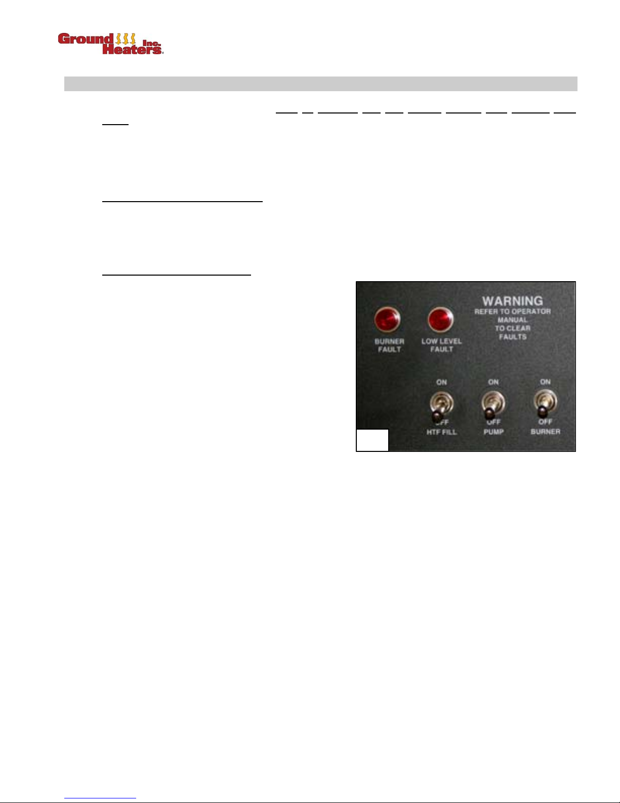
PUREHEAT™ HYDRONIC AIR HEATER OPERATOR’S MANUAL – SECTION 4
MAINTENANCE
The Pureheat™ Hydronic Air Heater must be operated only with Ground Heaters Heat Transfer Fluid
.
(HTF)
The standard Pureheat™ contains 145 US gallons (535 liters) of HTF for normal operation. Ground
Heaters, Inc. recommends that the HTF be replaced every three years to ensure that the corrosion
inhibitors are sufficiently active to protect the system components.
4.1 ADDING HEAT TRANSFER FLUID
(Refer to Appendix B-10)
NOTE: Shut down all pumps (including optional Booster Pump). (If using optional Booster Pump, refer
to Section 2.3.7, Optional Booster Pump.)
4.1.1 To Clear a “LOW LEVEL FAULT”
1. Place an open container of HTF close to the
manifold area to facilitate filling. The container
must be close enough to allow the 16 ft (4.9 m) fill
hose to reach the bottom of the container.
2. Power up the Pureheat™ as directed in Section
2.4, START UP.
3. Ensure that the PUMP and BURNER Switches
are OFF.
4. Ensure that a least one section of circulation hose
is connected to the supply and return manifolds to
complete a circulation loop.
5. Verify that valve #3 is shut.
6. Verify that valves #2 and #5 are open.
7. Pull out the fill hose (attached to valve #4). Clean the exterior and remove the fill hose dust cap.
4-1
8. Remove the locking pin from fill valve #4.
9. Direct the open end of the fill hose into the opening of the HTF container.
10. Momentarily open fill valve #4 until HTF is observed running out of the fill hose. This will “prime” the
fill hose.
11. Quickly close fill valve #4 to avoid over filling the HTF container.
12. Cover the open end of the fill hose to retain HTF after priming.
NOTE: If the HTF container height is such that it will not allow gravity flow from the Pureheat™ fill hose,
use a separate container with an opening low enough to facilitate priming the fill hose using the
method described.
13. Insert the fill hose into the HTF container, ensuring that the hose is not sealed against any interior
surface of the container.
14. Open fill valve #4. Immediately lift and hold the HTF FILL Switch to begin filling. (Photo 4-1)
15. Continue filling using the HTF FILL Switch until fluid is observed in the bottom of the sight gauge.
16. The LOW LEVEL RESET button may now be pressed to clear the low level shutdown condition. It is
not necessary to stop the filling process during this step. (Refer to Appendix B-10)
V. 2, Rev. 09/01/06 © 2006 Ground Heaters, Inc. 4- 1
Page 40
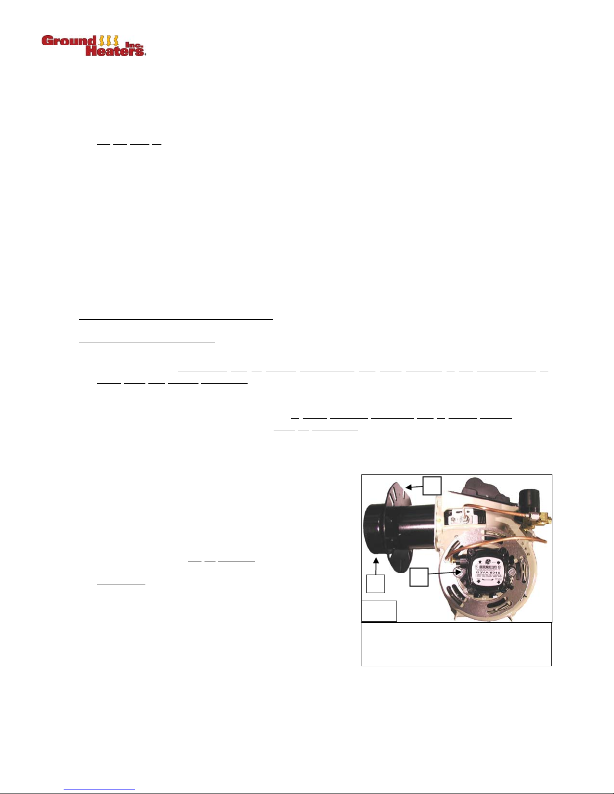
PUREHEAT™ HYDRONIC AIR HEATER OPERATOR’S MANUAL – SECTION 4
17. After the Low Level Shutdown device has cycled through a 15 second self test, the low level condition
will clear.
18. The PUMP Switch may now be turned ON, and the HTF FILL Switch released to finish filling.
19. Continue filling until the HTF level is between the MIN and MAX as observed in the HTF sight gauge.
Do
not over fill.
20. Once adequate HTF levels are verified in the Sight Gauge, remove the Fill Hose from the HTF
container but continue running the HTF pump. Elevate and outstretch the Fill Hose to clear excess
fluid from the hose.
21. Close fill valve #4 and insert the locking pin. Open Pump Suction Valve #3.
22. Clean the Fill Hose exterior and replace the dust cap. Stow the hose neatly in-between the HTF
Pump and the Supply/Return manifold rack.
NOTE: HTF Low Level Shutdown Device red (Low Water) light will blink for 15 seconds while device
performs self-diagnostic tests. After 15 seconds the red light will go out and the green light will
stay on, signaling the unit is ready to operate. The red LOW LEVEL FAULT light on the control
panel will also go out.
4.2 BURNER INSTALLATION/CHANGEOVER
4.2.1 From NG/LP to Diesel/Fuel Oil
1. Burner setup and installation, fuel supply connection, test-firing and Burner adjustment should be
performed by an experience
state and federal authorities.
local,
2. Main heater unit (trailer) must not be installed within 12 ft (3.6 m) of combustible materials.
3. To ensure proper Burner performance and to
combustion verification and adjustment must
• Before starting at a new job site.
• Before operating at altitudes 1,000 ft (305 m) above or below the last adjustment.
• After any Burner maintenance has been performed.
• After installing any Burner, even if it had been
previously used and calibrated.
• If Burner performance is in question for any reason.
4. A Combustion Analyzer, Smoke True Spot Tester and
common hand tools will
4.2.1.1 Installation
NOTE: All CF800 oil Burners are shipped by Ground Heaters,
Inc. with the proper nozzle (5.0 GPH 60º solid) installed
and the fuel pressure set at 150 psi.
1. Slide the flange gasket over the Burner air tube and
(Photo 4-2)
align the gasket with the mounting flange holes.
fuel oil Burner professional and must conform to the requirements of
be required.
avoid machine downtime due to heater sooting, Burner
be performed:
1
2
3
4-2
1. Burner Mounting Flange
2. Burner Air Tube
3. Burner Fuel Pump
2. Install the ½ in. insulation and the Burner mounting plate for the oil Burner (supplied when you
purchase an oil Burner) on the hydronic heater.
3. Insert the Burner air tube into the hydronic heater and install the four bolts which have been
supplied.
4- 2 © 2006 Ground Heaters, Inc. V. 2, Rev. 09/01/06
Page 41

PUREHEAT™ HYDRONIC AIR HEATER OPERATOR’S MANUAL – SECTION 4
4. Using the supplied 1¼ in. x
the trailer floor below the Burner. Extend the adjusting rod such that the round pad firmly
contacts the underside of the blower housing on the Burner. Tighten the jam nut to keep the
support rod from backing off.
5. Attach the 3-pin Quick-Connect Fuel Line power cord leading from the Main Control Panel to the
mating part located just below the Honeywell controller on the Burner.
6. Connect the Pigtails for the Burner Inline Fuel Heater. The Male portion is attached to the Burner
and the female portion is attached to the Main Control Panel.
7. Route the Supply and Return Fuel Lines from the Fuel Tank through the 5 in. (127 mm) square
access hole in the trailer floor below the Burner.
8. Using the Quick-Connect and hose barb supplied with the Oil Burner, attach the Supply Fuel Line
to the Fuel Filter on the Burner.
9. Attach the Return Fuel Line to the return hose Quick-Connect and hose barb on the Burner.
4.2.1.2 Setup
4.2.2 From Diesel/Fuel Oil to NG/LP
1. Set the Burner Air Band at 6 and Air Shutter at 6. These initial air settings will be fine tuned later.
2. With fuel in the remote tank, power up the Pureheat™ control panel as directed in Section 2.4,
START UP.
3. After the low level device runs through its self diagnostic cycle, the Burner should pre-purge and
then light. The oil primary control on the Burner may have to be re-set several times for the initial
start up to purge air out of the fuel supply line.
4. Follow procedures in Sections 3.2.1.1 through 3.2.1.4 to complete Burner adjustment.
5
/16 in. bolts, washers and nuts, install the Burner support bracket on
1. Burner setup and installation, fuel supply connection, test-firing and Burner adjustment should be
performed by a licensed
authorities
2. All gas and propane connections must be leak tested prior to placing into service.
3. Main heater unit (trailer) must not be installed within 12 ft (3.6 m) of combustible materials.
4. All gas Burners are test fired at Ground Heaters, Inc.'s factory prior to shipment.
5. To ensure proper Burner performance and to
combustion verification and adjustment must
• Before starting at a new job site.
• Before operating at altitudes 1,000 ft (305 m) above or below the last adjustment.
• After any Burner maintenance has been performed.
• After installing any Burner, even if it had been previously used and calibrated.
• If Burner performance is in question for any reason.
6. A Combustion Analyzer, Smoke True Spot Tester and common hand tools will
!
.
Do not exceed 14 in. water column gas supply
damage the gas train components.
Do not exceed 3.0 in. water column manifold pressure, as this will over-fire the
NG:
heater and cause damage.
Do not exceed 2.0 in. water column manifold pressure, as this will over-fire the
LP:
heater and cause damage.
professional and must conform to the requirements of local, state and federal
avoid machine downtime due to heater sooting, Burner
be performed:
be required.
pressure. Excessive pressure will
V. 2, Rev. 09/01/06 © 2006 Ground Heaters, Inc. 4- 3
Page 42
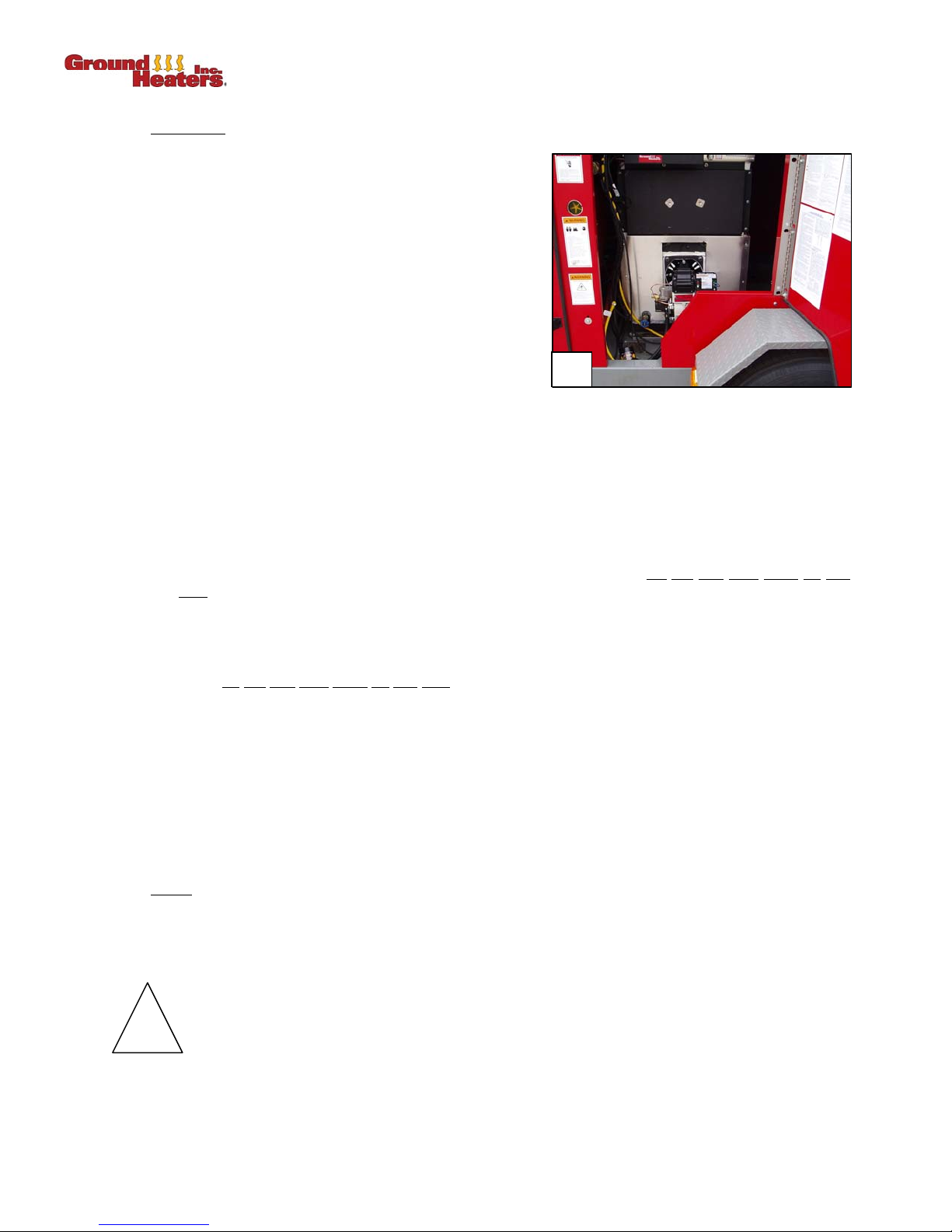
PUREHEAT™ HYDRONIC AIR HEATER OPERATOR’S MANUAL – SECTION 4
4.2.2.1 Installation
(Refer to Appendix A-24)
1. Remove the trailer enclosure lower panel located
2. Verify that the gasket is properly positioned on the
3. Insert the blast tube into the hydronic heater Burner
4. Using the supplied 1¼ in. x
5. Reinstall the enclosure panel next to the fender.
below the trailer's left side door adjacent to the
fender (to provide unrestricted access to the Burner
mounting plate on the Pureheat™ Hydronic Air
Heater). (Photo 4-3)
mounting flange and Burner blast tube.
mounting plate and attach with the four bolts which
have been supplied. The Burner should be oriented
with the Power Flame Model JR30A-12 label
oriented right side up.
5
/16 in. bolts, washers and nuts, install the Burner support bracket on
the trailer floor below the Burner. Extend the adjusting rod such that the square pad firmly
contacts the Burner support flange. Tighten the jam nut to keep the support rod from backing off.
4-3
6. Attach the 3-pin Quick-Connect Burner power cord leading from the Main Control Panel to the
connection socket located just behind the blue Honeywell™ Burner control.
7. Attach the gas train at the pipe union (secure to gas train mounting bracket), with the horizontal
portion of the gas train extending toward the tongue of the trailer. Do
.
joint
8. Attach the 2-pin Quick-Connect power cord leading from the Burner control to the electrical
junction box mounted on the gas train.
9. Connect the 90º end of the braided pilot gas line to the fitting provided on the left side of the gas
train. do
10. Verify that the two ball valves and the pilot valve on the gas train are turned OFF.
11. Attach the 36 in. x ¼ in. poly vent hose to the main gas pressure regulator vent and route it
outside through the 5 in. (127 mm) square access panel in the floor.
12. Attach the 17 in. x ¼ in. poly vent hose to the pilot pressure regulator and route it outside through
a slot in the trailer floor along the left side of the trailer.
13. Attach the NG or LP gas supply line to the main gas inlet fitting at the left side of the gas train.
This gas line should enter the trailer through the 5 in. (127 mm) square access panel in the floor
of the trailer.
4.2.2.2 Setup
1. Open the top Burner air inlet damper 100 percent. The bottom air inlet damper should be
completely closed. This initial setting will be fine tuned later.
2. Follow procedures located in Sections 3.1.1.1 through 3.1.1.4 to complete Burner adjustment.
not use pipe dope on this joint.
not use pipe dope on this
!
NOTE: The gas supply line must be sized such that it is capable of providing a minimum of 860 CFH NG
(or 344 CFH LP vapor) at 5 to 14 in. water column pressure.
Do not turn on the gas at this time.
4- 4 © 2006 Ground Heaters, Inc. V. 2, Rev. 09/01/06
Page 43
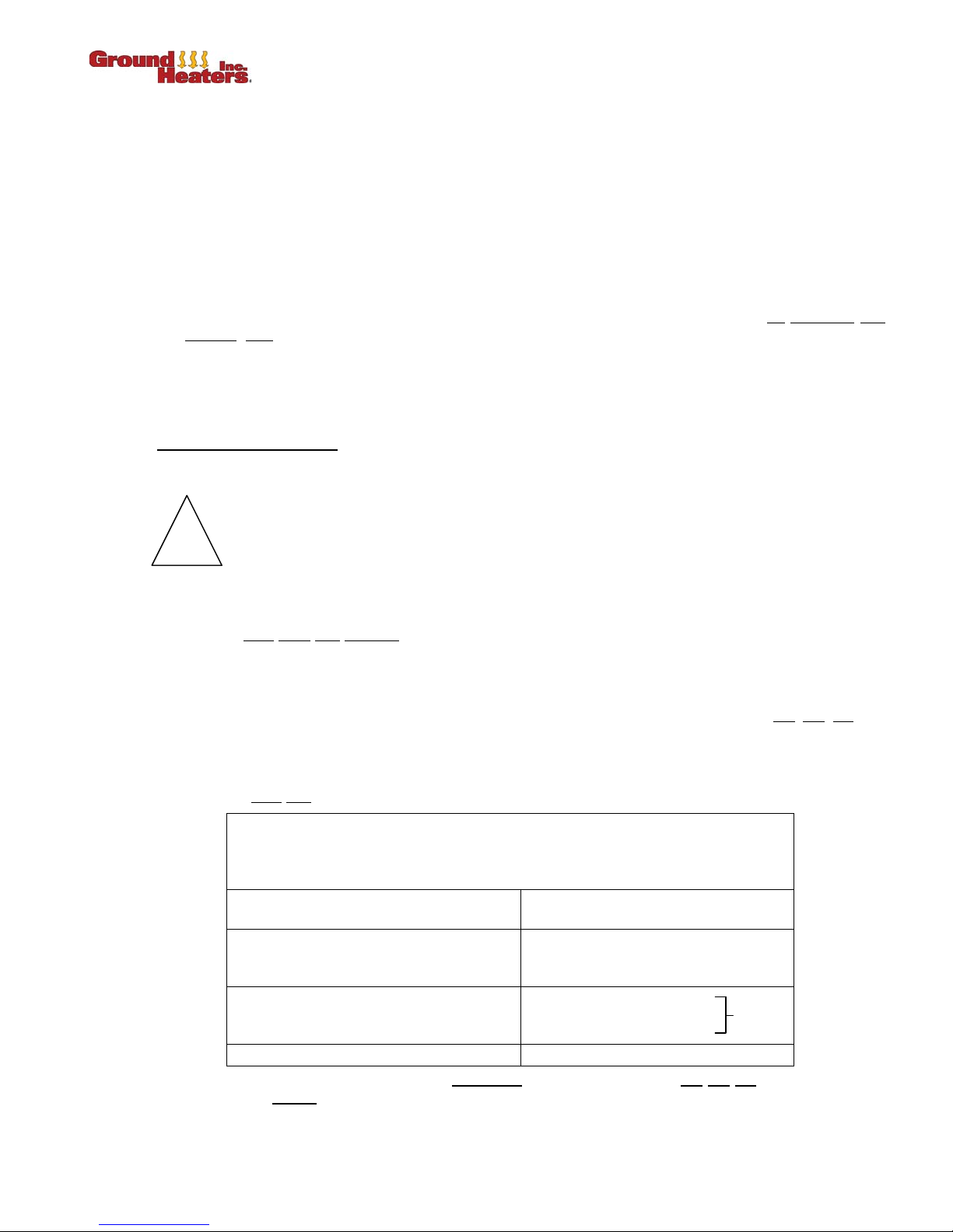
PUREHEAT™ HYDRONIC AIR HEATER OPERATOR’S MANUAL – SECTION 4
4.3 HIGH ALTITUDE OPERATIONS
1. The following procedures are recommended when operating the Pureheat™ at altitudes higher than
5,000 ft (1,524 m) asl. These procedures keep the Pureheat™ running smoothly and prevent the
possibility of premature soot build-up inside the hydronic heater fire tubes. ALL PROCEDURES
LISTED BELOW SHOULD BE PERFORMED BY CERTIFIED PERSONNEL AT YOUR GROUND
HEATERS DISTRIBUTOR.
2. When operating the Pureheat™ at high altitudes, the hydronic heater should be checked every 500
hours for sooting or other combustion abnormalities. Combustion Analyzer and Smoke Spot Tester
must be used for this test.
3. In addition to air adjustments, fuel pressure may be reduced to a lower pressure. To
burning
adjustment instructions.
NOTE: Always verify Burner exhaust O
pressure as directed in Section 3.1.1, Gas Burner Adjustment or 3.2.1, Diesel Burner Adjustment.
4.4 RECOMMENDED FUELS
1. Pureheat™ Hydronic Air Heaters are typically used outdoors, in cold weather.
!
2. Diesel fuel will thicken (gel) at low temperatures. Gelling (also known as waxing) may cause the
Burner not to light and/or fuel pump damage.
3. Contact your
for diesel fuel vary from terminal to terminal. Some fuel suppliers may add products such as
ValveTect to prevent gelling or Diesel 911 after gelling has occurred. Your fuel supplier should
supply this information and make recommendations for the selection and use of such products.
4. If ambient temperatures are such that your fuel supplier cannot insure the fuel will
Kerosene or #1 diesel fuel (dyed K1 for off-road use) must be added by ratio until gelling does not
occur.
rate, refer to Section 3, BURNER ADJUSTMENT AND SHUTDOWN for fuel pressure
and smoke levels after completing any adjustments to fuel
2
Care must be taken in selecting a fuel blend which will work properly in your jobsite
conditions.
local fuel supplier to obtain potential gelling temperatures for your fuel, as specifications
decrease fuel
not gel, K1
5. Refer to the Fuel Blend Guide, below; consult your fuel supplier for assistance in calibrating these
values to your
V. 2, Rev. 09/01/06 © 2006 Ground Heaters, Inc. 4- 5
fuel.
Low overnight ambient air temperatures can cause diesel fuels to gel.
Gelled fuel will cause the Burner not to light and/or fuel pump damage.
ALWAYS USE THE PROPER FUEL
LOWEST EXPECTED
AMBIENT AIR TEMPERATURE
Require your fuel supplier to guarantee that the fuel supplied will not gel at
the lowest
DIESEL FUEL SELECTION
PROPER
FUEL
100% #1 DIESEL
5ºF AND BELOW
100% K-1 KEROSENE
5ºF TO 25ºF
ABOVE 25ºF WINTER BLEND DIESEL
temperature which will be experienced at your work site.
OR
50% #2 DIESEL
+ BLEND
50% #1 DIESEL
Page 44

PUREHEAT™ HYDRONIC AIR HEATER OPERATOR’S MANUAL – SECTION 4
4.5 SUMMER STORAGE INSTRUCTIONS
1. Allow the heater to cool sufficiently. Cover the chimney and the Burner with plastic wrap or other
waterproof material. This will prevent corrosive moisture build-up and blockages caused by animal
nests. Burners not installed should be stored in a cool, dry place.
2. Remove emergency break-away battery and store the battery in a cool, dry place. Connect the
battery to a trickle charger once every 30 days to maintain full charge.
3. Perform a thorough inspection for leaks, and correct. Double-check that all valves are shut.
4. Ensure all manifold Quick-Connect covers are in place and secured.
5. Shut and lock all doors.
6. Protect the tires from direct sunlight if stored outdoors.
NOTE: Do not drain the HTF. The heater and plumbing must remain flooded with HTF to prevent
corrosion (rusting).
4.6 PRE-SEASON MAINTENANCE
(Refer to Section 3 of the Service Manual for detailed instructions.)
1. Remove all waterproof wrapping or covering from the chimney and Burner.
2. Test and reinstall emergency break-away battery.
3. Remove the Flue Access Door to inspect the Hydronic Heater Interior and fire tubes. Clean out any
soot or flaked material. Remount the Flue Access Door.
For Oil Burners
replacement. Adjust or replace the electrodes as necessary.
4. Remove the Burner to inspect and clean the flame head.
5. Replace fuel filter element.
6. Reinstall the electrode assembly and verify the “Z” distance is correctly set.
7. Remount Burner using a new Burner mounting gasket.
8. Adjust Burner settings as directed in Section 3, BURNER ADJUSTMENT AND SHUTDOWN.
9. Verify HTF level.
: Remove the Burner electrode assembly. Replace the nozzle with an exact
4- 6 © 2006 Ground Heaters, Inc. V. 2, Rev. 09/01/06
Page 45
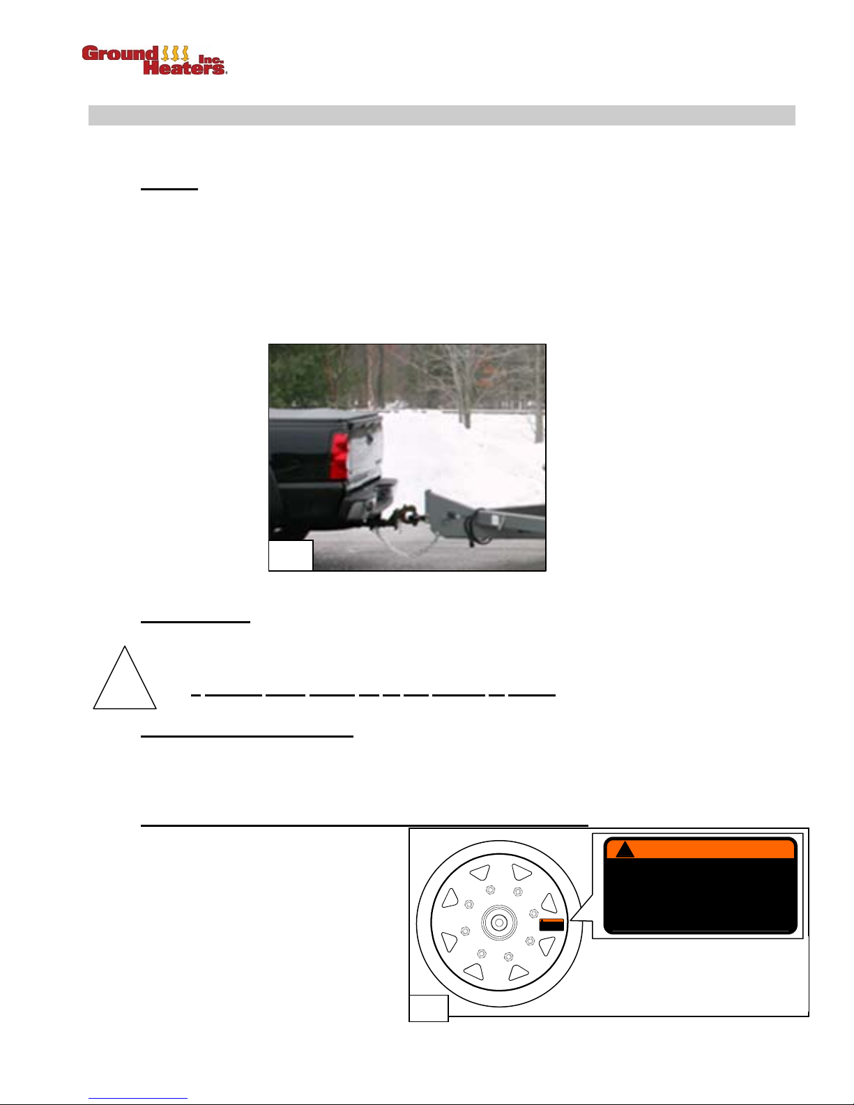
PUREHEAT™ HYDRONIC AIR HEATER OPERATOR’S MANUAL – SECTION 5
TRANSPORTING THE PUREHEATTM HYDRONIC AIR HEATER
This section describes the three basic methods of PureheatTM Hydronic Air Heater transport and
associated precautions.
5.1 TOWING
The Pureheat
TM
is easily towed by a vehicle rated to tow up to 8,500 lbs (3,855 kg) (HX Package) or
11,300 lbs (5125 kg) for the fuel tank package. The tow vehicle must be fitted with a Class V or above
hitch. (Photo 5-1)
TM
The Pureheat
has a tongue weight of 895 to 1,446 lbs (405 - 657 kg) depending on configuration.
Towing vehicle must be equipped with an electric brake system controller.
NOTE: A trailer plug wiring decal is located on the inside frame wall across from the trailer junction box.
(Refer to Appendix A-22 and Appendix A-23)
5-1
5.2 AERIAL LIFTING
The Pureheat
TM
is equipped with a lifting bail. The lifting bail has multiple holes to provide balance with
various configurations.
qualified rigger should set up and perform all rigging.
!
5.3 TRANSPORTING on a FLATBED
The Pureheat
ramps and docks. The Pureheat
A
TM
may be loaded onto a 98 in. (250 cm) or wider flatbed using common-sized loading
TM
should be chained down to the flatbed trailer.
(Refer to Appendix A-27)
5.4 COMMON MECHANICAL INSPECTIONS PRIOR TO TRANSPORTING
1. Trailer lights, brakes, wiring and
wheel bearing inspection.
2. Tires inflated to proper pressure and
free of defects.
3. Plumbing, internal and field hose
integrity check.
4. Lug nuts torque value is as directed
1
8
6
3
5
!
WARNING
FAILURE TO FOLLOW THESE INSTRUCTIONS
MAY RESULT IN WHEEL LOSS WHICH CAN
CAUSE INJURY OR DEATH!
TORQUE WHEEL NUTS TO 90–120 LB-FT
BEFORE FIRST ROAD USE. RETORQUE TO
90–120 LB-FT AFTER 10, 25 AND 50 MILES.
CHECK PERIODICALLY THEREAFTER .
4
7
2
on wheel decal. (Photo 5-2)
5-2
!
WARNING
FAILURE TO FOLLOW THESE INSTRUCTIONS
MAY RESULT IN WHEEL LOSS W HICH CAN
CAUSE INJURY OR DEATH !
TORQUE WHEEL NUTS TO 90–120 LB-FT
BEFORE FIRST ROAD USE. RETORQUE TO
90–120 LB-FT AFTER 10, 25 AND 50 MILES .
CHECK PERIODICALLY THEREAFTER.
Torque the wheel lug nuts
sequentially as shown.
Torque to the values listed on the
Warning decal located on the wheel.
V. 2, Rev. 09/01/06 © 2006 Ground Heaters, Inc. 5-1
Page 46
PUREHEAT™ HYDRONIC AIR HEATER OPERATOR’S MANUAL – SECTION 6
TROUBLESHOOTING
6.1 TROUBLESHOOTING CHART
(Contact your local Ground Heaters Distributor for situations not covered in this section.)
NOTE: Discontinue
following occurs:
the
1. One of the GFIs trips and will not remain reset.
2. An electric motor "hums" but does not turn.
3. The Burner Safety will not reset when the MANUAL RESET button is pushed.
4. Dark smoke emits from the hydronic heater exhaust.
Once the Pureheat™ is shut down; call your local Ground Heaters Distributor for assistance.
Symptom Possible Cause Corrective Action Refer To
Heat transfer
fluid pump will
not start.
Heat transfer
fluid pump
turns but does
not start.
troubleshooting activities and shut down the Pureheat™ Hydronic Air Heater if one of
No power due to incorrect switch
position or protective function.
Motor internal overload is
tripped.
Low voltage caused by
inadequate power supply; poor
quality; or excessively long
extension cords.
• Verify both
• Verify both
• Verify LOW LEVEL FAULT light is not
• Verify HTF level is between MIN and MAX.
• Allow motor to cool; it will reset
automatically.
• Have an electrician verify voltage at control
panel is 110 volts (min.) while
start
• Ensure power cords are at least 10 gauge
wires and ≤ 100 ft (30.5 m) in length.
• Verify power cords are supplied by
separate 20 amp 120 volts AC 60 Hz
electrical power circuits.
MAIN BREAKERS are ON.
GFIs are reset.
pump motor.
Appendix
lit.
Section 2
- - - - - - -
attempting to
- - - - - - -
A-2
HTF too cold (-20ºF [-28.9ºC]).
Heat transfer
fluid pump
turns but trips
breaker.
Burner motor
will not start.
V. 2, Rev. 09/01/06 © 2006 Ground Heaters, Inc. 6- 1
HTF too cold.
Low Voltage.
Pump pressure below 30 psi.
Insufficient power supply.
Power supply sufficient but no
power to burner motor.
• Warm HTF pump.
• Warm HTF pump.
• Correct low voltage.
• Throttle valve #2.
• Have an electrician verify voltage at burner
motor is 110 volts (min.) while attempting to
start burner motor.
• Ensure power cords are at least 10 gauge
wires and ≤ 100 ft (30.5 m) in length.
• Verify power cords are supplied by
separate 20 amp 120 volts AC 60 Hz
electrical power circuits.
• Call your Ground Heaters Distributor.
- - - - - - -
- - - - - - -
Section 2.4
- - - - - - -
- - - - - - -
Page 47
PUREHEAT™ HYDRONIC AIR HEATER OPERATOR’S MANUAL – SECTION 6
Symptom Possible Cause Corrective Action Refer To
MAIN BREAKERS are ON.
GFIs are reset.
Appendix
A-2
lit.
Section 2
Appendix
A-18
Burner motor will
not start
( . . .continued)
Improper switch position or
protective function action.
• Verify both
• Verify both
• Verify LOW LEVEL FAULT light is not
• Verify HTF level is between MIN and MAX
level.
• Verify LOW LEVEL SHUTDOWN DEVICE
is RESET.
Burner safety
trips (no flame).
Burner safety
trips
(flame occurs).
Heat exchanger
blower will not
start.
Burner Safety is tripped as
indicated by DIAGNOSTIC light
on burner control.
No fuel.
Insufficient voltage for ignition.
Control not sensing flame.
• No electrical power.
• Thermostat or speed selector
setting incorrect.
• Reset burner safety.
• Verify fuel supply is adequate.
• Verify both
connected (oil burner).
• Have an electrician verify voltage at
control panel is 110 volts (min.) while
attempting
• Ensure power cords are at least 10
gauge wire and ≤ 100 ft (30.5 m) in
length.
• Verify power cords are supplied by
separate 20 amp 120 volts AC 60 Hz
electrical power circuits.
• Call your Ground Heaters
• Verify 120 volts AC to heat exchanger.
• Set thermostat above room temperature.
• Set speed selector to desired fan speed.
fuel line Quick-Connects are
to start burner.
Distributor.
Appendix
A-10 or A-13
- - - - - - -
Section
4.2.1.1
- - - - - - -
- - - - - - -
- - - - - - -
Brake not fully released.
Rewind motor is too cold
Hoses will not
rewind.
If problem is not resolved by performing the above steps, call your Ground Heaters Distributor for assistance.
(rewind motor may not start if
below 0ºF [-18°C]).
Faulty foot pedal.
6- 2 © 2006 Ground Heaters, Inc. V. 2, Rev. 09/01/06
• Fully release hose reel brake.
• Warm rewind motor.
• Call your Ground Heaters Distributor.
Section
2.6.3
- - - - - - -
- - - - - - -
Page 48
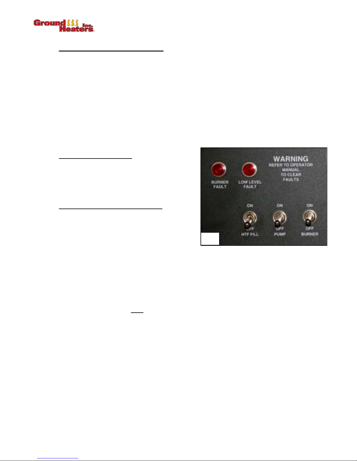
PUREHEAT™ HYDRONIC AIR HEATER OPERATOR’S MANUAL – SECTION 6
6.2 HTF LOW LEVEL FAULT AND LIGHTS
(Refer to Appendix A-18)
Perform the following when HTF LOW LEVEL FAULT light (refer to control panel) is it: (Photo 6-1)
1. Turn BURNER, PUMP and REWIND MOTOR switches OFF.
2. Locate and correct cause of low HTF condition (i.e. fix the leak).
3. Restore HTF level to normal operating level per Section 4.1, ADDING HEAT TRANSFER FLUID.
4. Depress MANUAL RESET button to clear low level condition. Reset will complete in 15 seconds.
NOTE: Call your Ground Heaters Distributor if HTF level is between MIN and MAX and:
• Low Level Shutdown device will not reset;
• LOW LEVEL FAULT light (refer to control panel) remains on after depressing the Low level
Shutdown device RESET button; or
• Burner control locks out the burner and will not remain reset.
6.2.1 Low Level Shutdown Device
The LOW LEVEL FAULT light is activated for 15
seconds after initial power up and then goes out.
Reset is accomplished by pressing the RESET
button for 1 to 2 seconds or by momentarily shutting
OFF BREAKER 1.
6.2.2 Testing the Low Level Shutdown Device
Power up the main control panel by following the
steps outlined in Section 2.4, START UP.
Observe the LOW WATER and POWER lights on
the bottom of the Low Level Shutdown Device.
Ensure that the Green POWER light is ON and the
Red LOW WATER light is OFF.
LOW LEVEL FAULT
Press and hold the TEST button while monitoring the red LOW WATER light.
The red LOW WATER light will flash 10 times followed by the main control panel LOW WATER light will
be on.
The green POWER light and the LOW WATER light will both be ON.
Verify that the LOW LEVEL FAULT light is ON at the main control panel.
Turn the PUMP and the BURNER switches ON one at a time at the main control panel to verify that the
PUMP AND BURNER ARE NOT
RESET
Turn the PUMP and BURNER switches OFF.
Momentarily press the RESET button. The LOW WATER and POWER lights will flash simultaneously 4
times and the POWER light will return to normal operating mode. The LOW WATER light will continue to
flash an additional 14 times and return to normal operating mode. The POWER light will be ON, the LOW
WATER light will be OFF and the LOW LEVEL FAULT light at the main control panel will be OFF.
Turn the burner switch ON and the burner will start after a five second delay. After the burner starts, turn
the BURNER switch OFF.
Turn the pump switch ON and the pump will start immediately. Turn the PUMP switch OFF.
If the test does not conform to the instructions and results as outlined above, call your Ground Heaters
distributor.
OPERATIONAL.
6-1
V. 2, Rev. 09/01/06 © 2006 Ground Heaters, Inc. 6- 3
Page 49

PUREHEAT™ HYDRONIC AIR HEATER OPERATOR’S MANUAL – SECTION 6
6.3 BURNER CONTROL LOCKOUT
(Refer to Appendix A-13 or A-8 through A-14)
6.3.1 Gas Burner Control
The POWER light will illuminate only during the heating cycle. After flame is established, the POWER,
PILOT, MAIN and FLAME lights should all be illuminated.
If flame failure of any nature is sensed during the start up or heating cycle, the control will stop all burner
function and begin Lockout mode.
Lockout Mode
• ALARM light will illuminate
• PILOT, FLAME and MAIN lights will go out.
Momentarily press the RESET button to clear the lockout condition.
6.3.2 Oil Burner Control
The DIAGNOSTIC light (green LED) will illuminate during the heating cycle after the 15 second pre-purge
time has elapsed and flame has been established.
If flame failure is sensed during the start up or heating cycle, the control will stop all burner function and
begin one of three protective modes:
1. Recycle Mode
The DIAGNOSTIC light will flash in two second intervals while attempting three automatic restarts. If
the flame fails after three successive attempts, the control will go into Lockout mode.
2. Lockout Mode
The DIAGNOSTIC light will flash in one-half second intervals.
The RESET button must be momentarily pressed to clear the lockout and attempt a burner restart.
After three attempts to manually clear the lockout mode, the control will begin Restricted Lockout
mode.
3. Restricted Lockout Mode
The DIAGNOSTIC light will flash in one-half second intervals.
The RESET button must be pressed and held for 30 seconds or until the DIAGNOSTIC light comes
on for two seconds and then goes out.
The control will return to Restricted Lockout mode with each flame failure until one successful heating
cycle has occurred.
6- 4 © 2006 Ground Heaters, Inc. V. 2, Rev. 09/01/06
Page 50
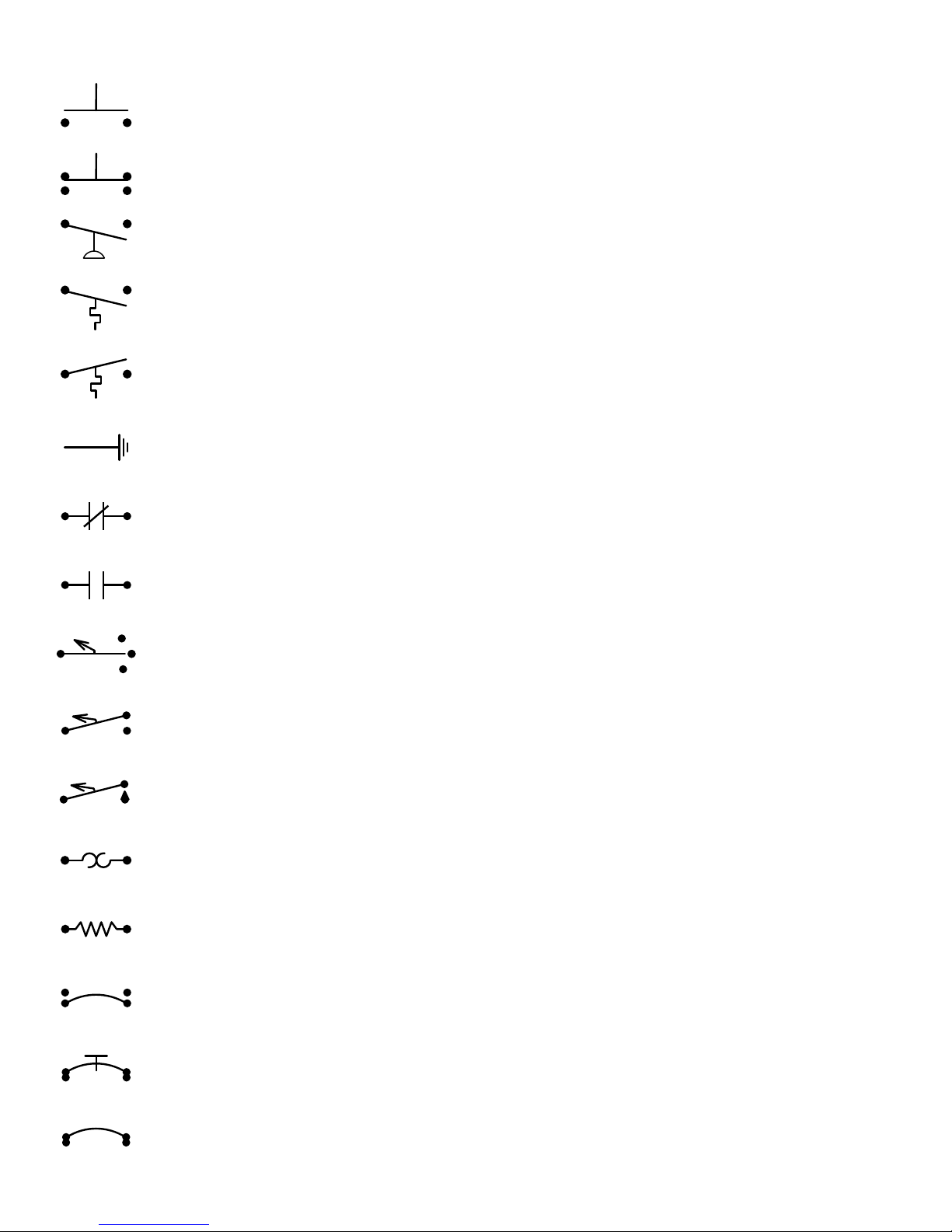
SCHEMATIC AND WIRING DIAGRAM SYMBOL LEGEND
PUSH BUTTON SWITCH, MOMENTARY, NORMALLY OPEN: A momentary push button switch that CLOSES on activation (makes
contact when pushed) such as the LOW OIL PRESSURE OVERRIDE Switch
PUSH BUTTON SWITCH: A two position push button switch such as the EMERGENCY STOP Switch
PRESSURE SWITCH, MAKES ON RISE: A pressure operated switch that CLOSES (makes contact) on an increase in pressure.
THERMOSTAT, MAKES ON RISE: A temperature operated switch that CLOSES (makes contact) on an increase in temperature
THERMOSTAT, BREAKS ON RISE: A temperature operated switch that OPENS (discontinues contact) on an increase in temperature
GROUND: May be used to show a frame (chassis) ground or a neutral connection.
NORMALLY CLOSED CONTACTS (N.C.): Relay contacts that are SHUT (making contact) when the relay coil is not powered or
energized.
NORMALLY OPEN CONTACTS (N.O.) : Relay contacts that are OPEN (not making contact) when the relay coil is not powered or
energized.
TOGGLE SWITCH, TWO POSITION: An ON – OFF – ON bat handled switch such as the REWIND CLUTCH switch.
TOGGLE SWITCH: An OFF or ON bat handled switch such as the BURNER switch.
MOMENTARY TOGGLE SWITCH: A bat handled switch that automatically returns to the OFF position when released.
THERMAL FUSE: A fuse, motor overload or other heat reactive protective switch
RESISTIVE LOAD: Relay coils, resistance heaters, resistors.
SNAP DISC, MAKES ON RISE, AUTO RESET: A bi-metal disc that CLOSES a switch should the temperature of the media it is sensing
reach the set point (usually fixed). The Switch will return to its normal position after the temperature drops to a pre-determined level.
SNAP DISC, BREAKS ON RISE, MANUAL RESET: A bi-metal disc that OPENS a switch should the temperature of the media it is
sensing reach the set point (usually fixed). The Switch can be reset only after after the temperature drops to a pre-determined level.
This type of switch is commonly used as a high limit.
SNAP DISC, OPENS ON RISE, AUTO RESET: A bi-metal disc that OPENS a switch should the temperature of the media it is sensing
reach the set point (usually fixed). The Switch will return to its “normal” position after the temperature drops to a pre-determined level.
This type of switch is commonly used as a high limit.
V. 2, Rev. 09/01/06
© 2006 Ground Heaters, Inc.
A – 1a
Page 51

SCHEMATIC AND WIRING DIAGRAM SYMBOL LEGEND
xx
1
BLK
RED
WHT
1
1
1
0 1
CR-1
TERMINAL STRIP CONNECTION POINT: Provides a transitional connection from Main Control Panel internal wiring and Main Control
Panel exterior wiring.
Note: Terminal strip connection point numbers are the same as the wires attached
TERMINAL IDENTIFIER: Identifies specific terminals on components with labeled terminals.
WIRE COLOR DESIGNATION: Identifies wire colors.
COLOR AND WIRE NUMBER DESIGNATIONS: Identifies wires by number and color to simplify troubleshooting.
CONNECTION POINT: A general connection point symbol used primarily on schematics to represent common connections such as wire
nuts, lug screws or piggy-backed disconnects.
GENERIC LOAD: Relays, Motors and electrically operated valves etc.
YELLOW WIRE NUT: Used to connect several wires. It is larger than the common orange wire nut and typically used with up to six 16 –
18 gauge wires.
ORANGE WIRE NUT: Used to connect two or more 16 – 18 gauge wires.
WIRE CAGES: Used to connect up to five 16 – 18 gauge wires.
DUPLEX OUTLET: A receptacle used to plug in various loads such as a strobe light, Pump Pack or small resistance heaters..
1
2
ROTARY SWITCH: A common selector switch for various functions such as multi speed motors.
3
4
5
WIRE JUMP: Used to show wires that are adjacent but are not connected to each other.
CONNECTION POINT: Used to show wires that are connected to each other by common means such as a lug, wire nut or crimp-on
connector.
A – 1b
© 2006 Ground Heaters, Inc.
V. 2, Rev. 09/01/06
Page 52
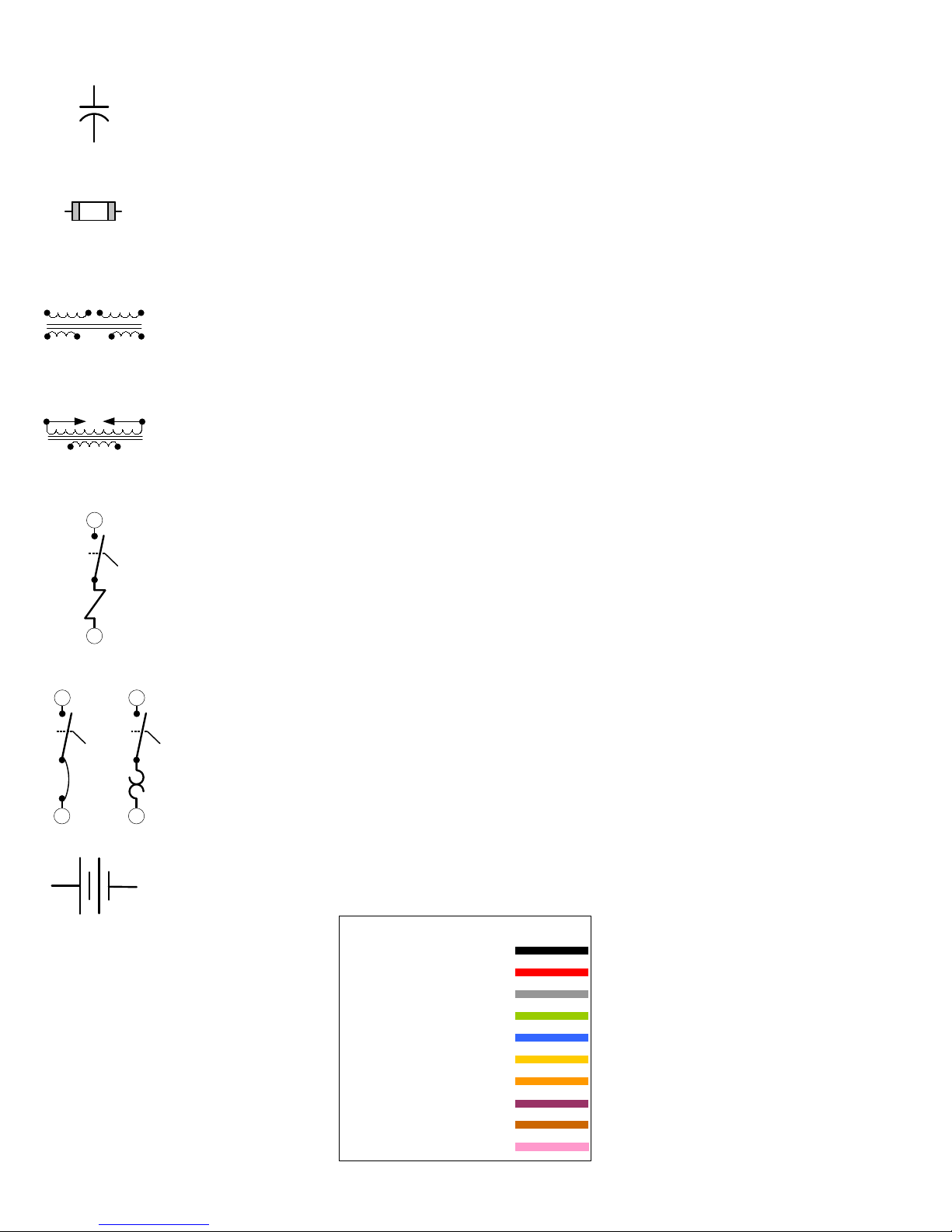
FNM-3
SCHEMATIC AND WIRING DIAGRAM SYMBOL LEGEND
CAPACITOR: Used to add starting torque and efficiency to single phase electric motors.
Capacitors are rated by Microfarad (µf or mfd) and volts i.e.: 10 µf 370V = Ten Microfarads x Three Hundred Seventy Volts.
FUSE: Single use glass or fiber case fuses commonly used in electrical circuitry.
Their capacity is listed in the type number of the fuse i.e FNM-3 is a fuse with a Three Amp rating.
STEP DOWN TRANSFORMER: Used in GHI equipment to reduce 120 Volts AC to 12.6 Volts AC.
CB-2
20A
LINE
LOAD
IGN. TRANS.
LINE
CB-2
20A
LOAD
CB-2
OR
IGNITION TRANSFORMER: Increases 120 Volts AC up to 30,000 Volts to generate the high energy spark
required to ignite fuel.
MAGNETIC CIRCUIT BREAKER: Trips when the electrical energy level through the breaker generates electromagnetic force in
amounts sufficient to activate a mechanical (electromagnetic) device to force the Switch OPEN.
LINE
20A
THERMAL CIRCUIT BREAKERS: Trips when the electrical energy level through the breaker generates heat in amounts sufficient
to activate a thermo-mechanical (Bi-Metal) device to force the Switch OPEN.
LOAD
BATTERY: Typically 12 Volts DC batteries are used to start Generators or to provide power for Electric Trailer Brakes.
V. 2, Rev. 09/01/06
COMMON WIRE COLORS
BLK = BLACK
RED = RED
WHT = WHITE
GRN = GREEN
BLU = BLUE
YEL = YELLOW
ORG = ORANGE
VIO = VIOLET
BRN = BROWN
PNK = PINK
© 2006 Ground Heaters, Inc.
A – 1c
Page 53
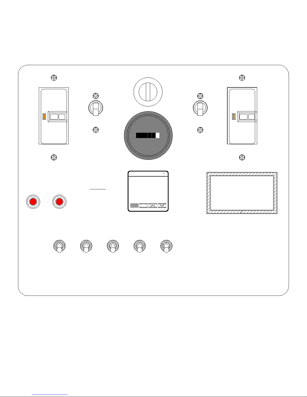
PUREHEAT CONTROL PANEL EXTERIOR LAYOUT
BURNER
FAULT
ON OFF
LINE1GFI
LOW LEVEL
FAULT
MAIN
BREAKER 1
o
WARNING
REFER TO OPERATOR
MANUAL
TO CLEAR
FAULTS
FUJI
ELECTRIC
C1 C2
PV
SV
PXR-4
TEMPERATURE
000 000
HOURS
AL1AL3AL
2
CONTROL
MAIN
BREAKER 2
o
ON OFF
LINE 2 GFI
F
ON
OFF
HTF FILL
ON
OFF
PUMP
ON
OFF
BURNER
ON
OFF
HOSE
REWIND
ON
OFF
CAB
LIGHT
A - 2
© 2006 Ground Heaters, Inc.
V. 2, Rev. 09/01/06
Page 54
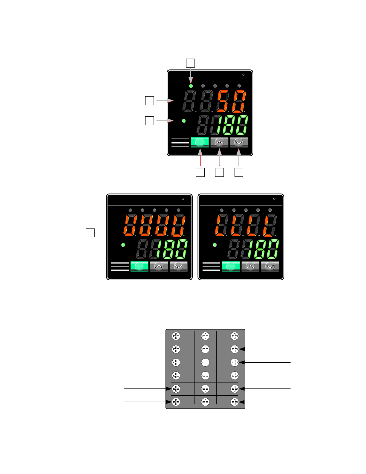
PUREHEAT TEMPERATURE CONTROL
FUJI
MODEL PXR-4
HEATING DEMAND INDICATORA
A
PROCESS VALUE (HTF TEMPERATURE)B
SET-POINT VALUE (DESIRED TEMPERATURE)C
NOT USEDD
DISPLAY DURING THERMOCOUPLE
E
(SENSOR) CONNECTION LOSS
DECREASE TEMPERATURE
-
INCREASE TEMPERATURE
+
E
FUJI
ELECTRIC
C1 C2 AL1 AL3AL2
PV
SV
FUJI
ELECTRIC
C1 C2 AL1 AL3AL2
B
C
PV
SV
PXR-4
SEL
D
F
+ -
FUJI
ELECTRIC
C1 C2 AL1 AL3AL2
PV
SV
F
F
SEL
PXR-4PXR-4
WIRE #1,1 120 VOLTS
WIRE #2,2 NEUTRAL
SEL
PXR-4PXR-4
FUJI TEMPERATURE
CONTROL WIRING
1
2
3
4
5
6
13
7
14
8
15
9
16
10
17
11
12
18
WIRE #1 120 VOLTS
WIRE #22 TO RELAY COIL CR2
THERMOCOUPLE + (BLUE)
THERMOCOUPLE – (RED)
V. 2, Rev. 09/01/06
© 2006 Ground Heaters, Inc.
A - 3
Page 55
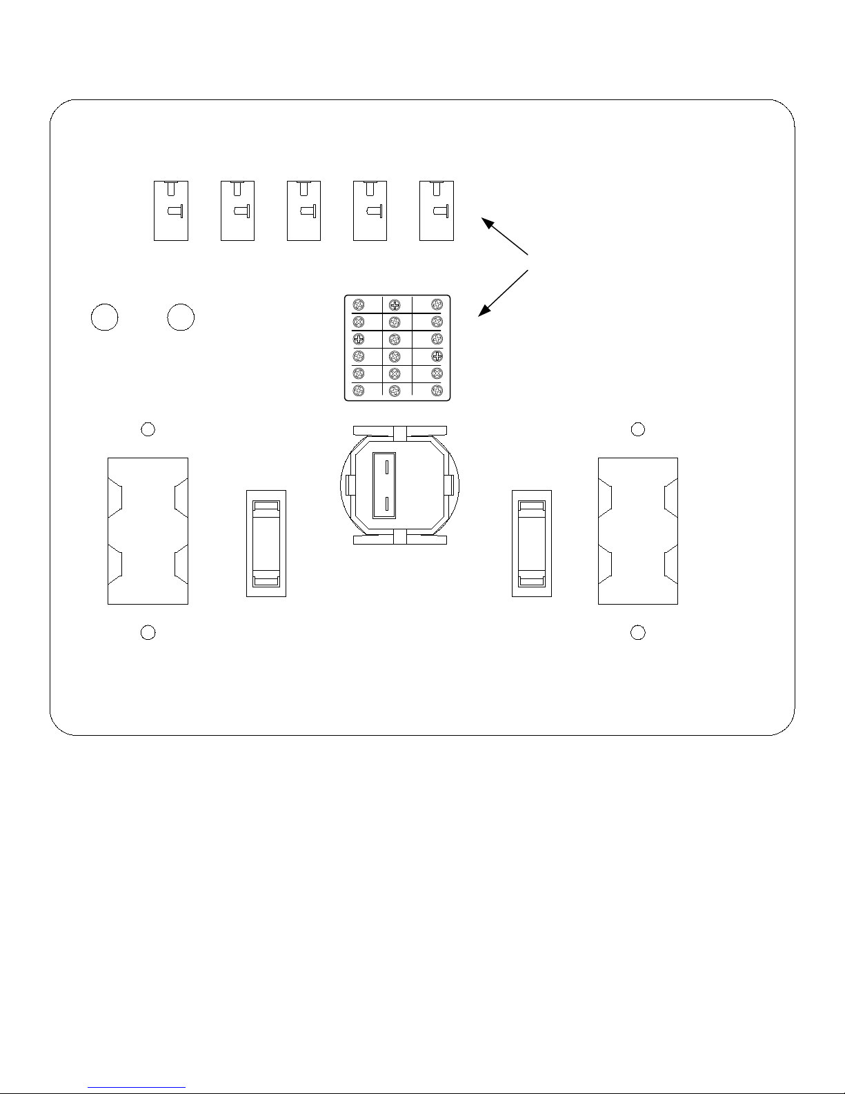
PUREHEAT CONTROL PANEL DOOR INTERIOR LAYOUT
2
27
BURNER
FAULT LIGHT
1
HTF FILL
LOW LEVEL
FAULT LIGHT
LINE 1 GFI
SW.
1,1
9,9
PUMP
SW.
19
9
BURNER
SW.
14
HOSE REWIND
SW.
18
21
15
CAB LIGHT
SW.
1,1
5
WIRE NUMBERS SHOWN IN BOLD
TEMPERATURE
CONTROL
2
20
1,1
1
2
3
4
5
6
2
MAIN
BREAKER 1
13
7
14
8
9
10
11
12
1
15
22
16
17
BLU
RED
18
MAIN
BREAKER 2
LINE 2 GFI
2, 2
2
13
L3
L4
26
17
L3
N1
G
L1
HOURS
L2
L4
N2
G
A - 4
© 2006 Ground Heaters, Inc.
V. 2, Rev. 09/01/06
Page 56

PUREHEAT MAIN CONTROL PANEL
EXTERIOR COMPONENT FUNCTION AND IDENTIFICATION
DOOR COMPONENTS
BREAKER 1 CURVE 10 15 AMP. (P/N E100-354):
Provides ON and OFF power control and circuit protection for electrical circuit one.
BREAKER 2 CURVE 10 20 AMP. (P/N E100-123):
Provides ON and OFF power control and circuit protection for electrical circuit two.
LINE 1 GFI (P/N E100-093):
A Ground Fault Circuit Interrupter (GFI) which provides operator protection for electrical circuit one.
LINE 2 GFI (P/N E100-093):
A Ground Fault Circuit Interrupter (GFI) which provides operator protection for electrical circuit two.
HOUR METER (P/N E100-096):
A meter to record total hours of use. The Hour Meter functions only when the BURNER Switch is turned ON and does
burner run time.
TEMPERATURE CONTROL (P/N E100-084):
Provides ON and OFF control of the Burner based on set-point (desired temperature) as well as primary high and low temperature limit
functions. The digital display panel indicates the Heat Transfer Fluid (HTF) temperature in red, the set-point (desired temperature) in
green and output indication (demand for heat) by illuminating the C1 light in the upper left of the display panel. Set-point is adjusted using
the UP and DOWN arrow Keys located below the display panel.
not reflect actual
BURNER FAULT LAMP (P/N E100-353):
Indicates the Burner Control has sensed flame failure and has entered BURNER FAULT mode. All Burner functions are disabled during
BURNER FAULT mode except for the Inline Fuel Heater (oil burner only) which is powered directly by the BURNER Switch.
LOW LEVEL FAULT LAMP (P/N E100-353):
Indicates that the Low Level Shut Down Device sensed an HTF loss and has entered LOW LEVEL FAULT mode. All Burner and Pump
functions are disabled except for the Inline Fuel Heater (oil burner only) which is powered directly by the BURNER Switch.
HTF FILL SWITCH (P/N E100-230):
Used to operate the Pump during a LOW LEVEL FAULT to effect re-filling of HTF.
PUMP SWITCH (P/N E100-101):
Provides operation and control of the HTF Pump.
BURNER SWITCH (P/N E100-101):
Provides ON or OFF power control to the Burner.
REWIND MOTOR SWITCH (P/N E100-101):
Provides ON or OFF power control to the Rewind Motor.
CAB LIGHT SWITCH (P/N E100-101):
Provides ON or OFF power control to the Interior Cab Light.
V. 2, Rev. 09/01/06
© 2006 Ground Heaters, Inc.
A - 5
Page 57
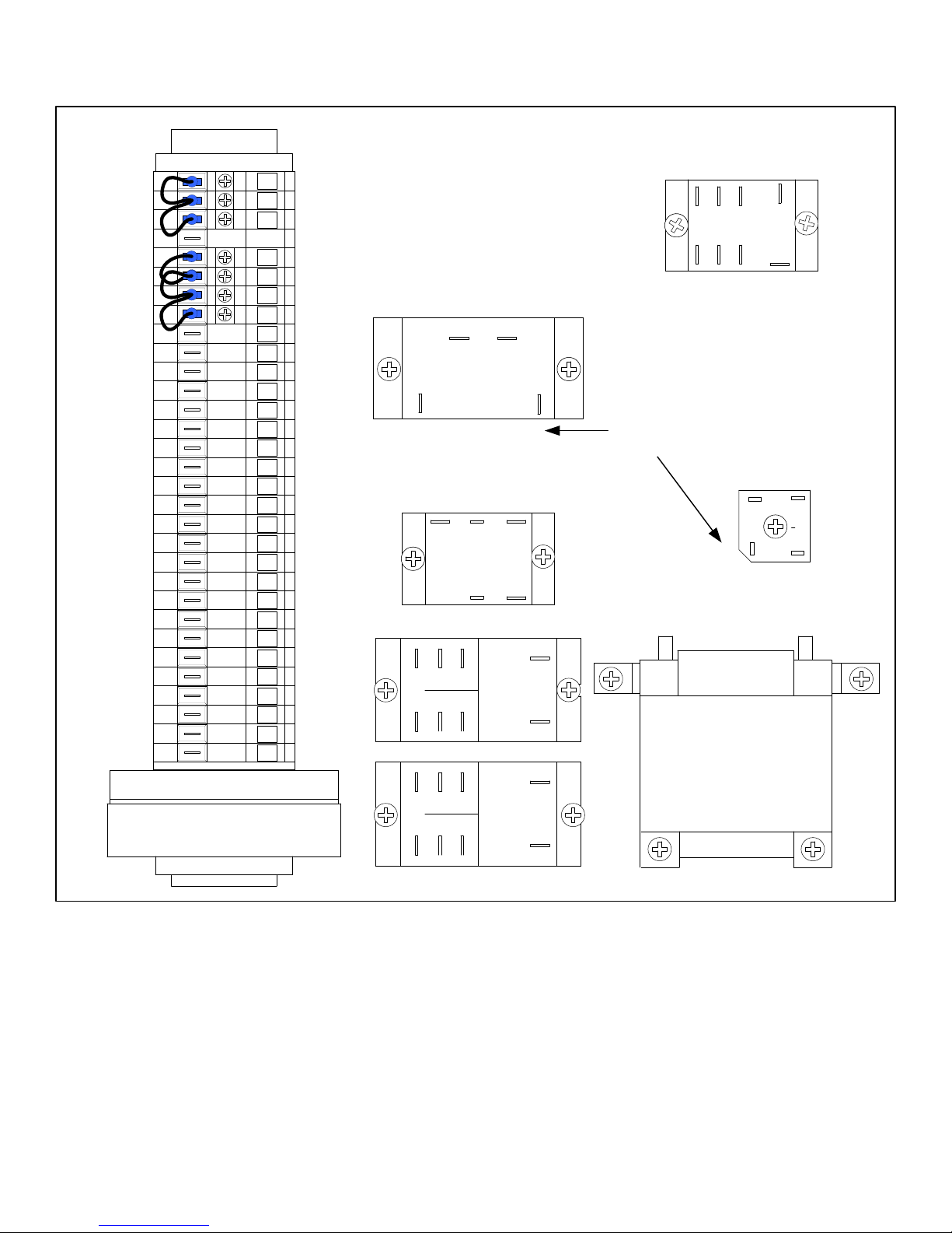
25
18
FUSE 2 3AG 5.0-SB
P/N E100-356
FUSE 1 FNM-3
1
1
1
2
2
2
2
3
4
5
6
7
8
9
10
25
11
12
13
14
15
16
17
18
24
26
L2
N2
L1
N1
P/N E100-357
PUREHEAT MAIN CONTROL PANEL
INTERIOR COMPONENT LAYOUT
26 16
2 3
CR4
6
29
13 10
COM NO
COIL
CR3
COIL
24 3
3
42
12 11
6
8
7
42
23
1
19
6 78
21
3
1
120
27
NC
22
CR2
2
4
CR1
5
WIRE NUMBERS
SHOWN IN BOLD
0
1
0
2
1
24
Jumper 26
Blank
Blank
Jumper 26
23
327
6
13
CR3
24,24
RECTIFIER
T1
10
24
8
-
~
~
+
25
18
2
Blank
Blank
18
2
CR 1&2 RELAY, 120VAC, FLANGE MOUNT, 30A P/N E100-205
CR- 4 RELAY, 120VAC, 30A, 1 ½ HP P/N E100-359
CR- 3 RELAY, 12VAC, FLANGE MOUNT, 25A P/N E100-382
TRANSFORMER, 80VA, 120/240:12.6
RECTIFIER, BRIDGE, FULL WAVE, 25A, 200V P/N E100-225
A - 6
© 2006 Ground Heaters, Inc.
P/N E100-220
V. 2, Rev. 09/01/06
Page 58

PUREHEAT MAIN CONTROL PANEL
INTERIOR COMPONENT FUNCTION AND IDENTIFICATION
PANEL INTERIOR COMPONENTS
CR-1 RELAY (P/N E100-205):
Relay CR-1 is controlled by the Low Level Shutdown Device contacts C - B (NO) (normally open). Relay CR-1 contacts 8 – 7 (N.C.)
(normally closed) control the 120V power to the LOW LEVEL FAULT light. CR-1 relay contacts 6 – 8 (N.O.) control the 120V power to
the BURNER switch.
CR-2 RELAY (P/N E100-205):
Relay CR-2 is controlled by the normally open (NO) contacts 14 – 15 of the FUJI Temperature Control. Relay CR-2 contacts 6 – 8 (N.O.)
are connected in parallel to the 3T & T connections on the Burner Control. Opening and closing relay contacts 6 – 8 will initiate or
terminate the heating cycle.
CR-3 RELAY (P/N E100-382):
Relay CR-3 is controlled by the internal alarm contacts of the burner control (diesel burner) or by Relay CR-5 contacts COM and NO (LP/
NG burner). The Relay CR-3 controls 120V power to the Accessories Power Receptacle via contacts COM and NC. The BURNER FAULT
light is controlled by Relay CR-3 contacts COM and NO. 120V power to the Relay CR-3 COM is controlled by Relay CR-1 contacts 6 –8
via the BURNER switch.
CR-4 RELAY (P/N E100-359):
Relay CR-4 Operating Coil is energized (powered) by the PUMP switch. Relay CR-4contacts 2 – 3 (N.O.) control the 120V power to the
HTF Pump.
CR-5 RELAY (P/N E100-383): (LP/NG burner only)
Relay CR-5 is controlled by the burner control’s alarm contacts..
Relay CR-5 contacts COM – N.O. close during a burner fault to power the Relay CR-3 12 volt DC coil. Relay CR-5 is located beneath
Burner Control.
T-1 TRANSFORMER (P/N E100-220):
Reduces 120 volts AC
RECTIFIER (P/N E100-225):
Converts 12.6 volts AC
FUSE 1 TYPE FNM-3 (P/N E100-356):
Provides circuit protection for the Rewind Motor and the line voltage portion of the Rewind Circuit.
FUSE 2 TYPE 3AG, 5.0 SB (P/N E100-357):
Provides circuit protection for the low voltage portion of the Rewind Circuit.
TERMINAL STRIP:
A transitional connection point between control panel interior and exterior components.
Numbered connection points share the same number as the wire connected to them.
current to approximately 12.6 volts AC current.
current to 12.6 volts DC current as an operator safety feature of the rewind circuit.
the
V. 2, Rev. 09/01/06
© 2006 Ground Heaters, Inc.
A - 7
Page 59
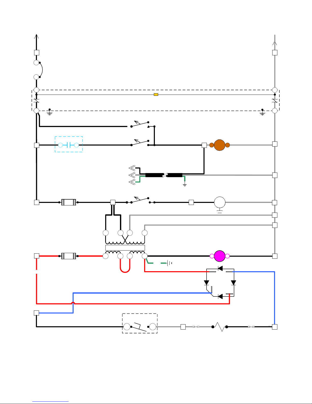
PUREHEAT WIRING SCHEMATIC
CIRCUIT 1
(SHEET 1)
11
LINE
CB-1
15A
LOAD
LINE
LOAD
1
1
11
L3
BLK
1
1
L1
+120VAC
GFCI-1
1
CR-1
FU-1
FNM-3
19
18
BLK
N1
N1
LINE
LOAD
GROUND FAULT INDICATOR LAMP
ILLUMINATES DURING GROUND FAULT
GFCI-1
HTF FILL SW.
1
2
9
9
CR-4
5 64 2
9
WHT
2
PUMP SW.
A
B
AUX PUMP CABLE
WHT
2
2
C
REWIND MOTOR
1/6 HP 2.1A
18
18
120V
1515
15
MTR-2
2
WHT
WHT
WHT
2
2
2
2
1526
25
25
FU-2
3AG 5.0 SB
23
RED
7 8 11
RED
6
BLU
25
RED
6
6
BLK
A - 8
TX-1
12V
26
COM N.O
12
GRN
24
RED
FOOT SW.
© 2006 Ground Heaters, Inc.
WHT
12VAC
24
12VDC
COIL COIL
CR3
~
RECTIFIER
P/N E100-218
+
REWIND CLUTCH
3.9A, 12V DC
7
7
7
WHT
10
-
BLU
10
~
8
BLK
8
V. 2, Rev. 09/01/06
Page 60
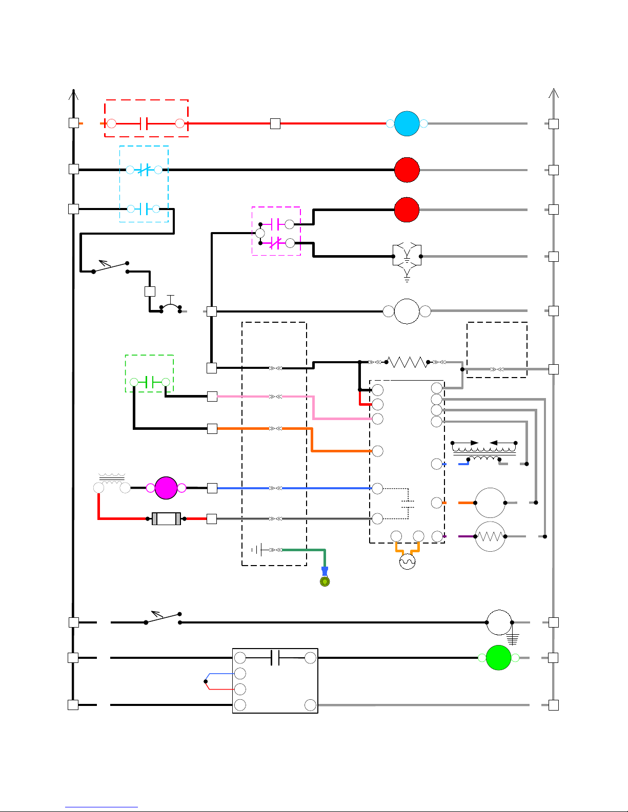
1
BLK
1
1
1
1
ORG
1
1
BLK
BURNER SW.
1
BLK
BLK
C
TX-1
120V
12V
LOW LEVEL
CR1-1
CR1-1
8
21
BLK1414
C
6 8
24
127
25
B
78
6
TS1
14
200 º F.
MANUAL RESET
BI-METAL DISC
R
2
12VAC
12VDC
COIL COIL
CR3
FU-2
3AG 5.0 SB
PUREHEAT WIRING SCHEMATIC
(SHEET 2)
CIRCUIT 1 WITH DIESEL BURNER
13
WHT
11
12
10
13
13
11
11
11
12
12
12
10
10
25
25
RED
4
13
13
13
(PNK) PIN-F (RED)
11
12
10
PIN C (WHT/BLK)
25
4
CR3
NO
COM
NC
BURNER
CABLE
PIN-A (BLK)
PIN-E (ORG)
PIN-D (BLU)
PIN-G (GRN)
RED
4
20
27
3
13
11
12
10
25
0 1
LOW LEVEL FAULT LAMP
BURNER FAULT LAMP
RECEPTACLE
HOUR METER
25 WATT (.2 A)
FUEL PRE-HEATER
L1
LIMIT
T
BURNER
CONTROL
3T
ALARM
C+ C-
CR1
R
R
N
2
WHT
2
2
WHT
2
2
WHT
2
2
WHT
2
WHT
-+
BURNER
CABLE
2
2
PIN-B (WHT)
2
L2
L2
L2
L2
IGN. TRANS.
BLU
IG
WHT
BURNER MOTOR
BM
ORG
VIO
V
4.8
FLA.
WHT
WHT
CAB LIGHT SW.
1
BLK
1
1 WHT
1
1
BLK
THERMOCOUPLE,
TYPE T
V. 2, Rev. 09/01/06
BLU
RED
BURNER
GROUND
14
15
17
DIGITAL
18
TEMPERATURE
CONTROL
5
6
© 2006 Ground Heaters, Inc.
OIL VALVE
CAD CELL
WHT
2
2
CAB LIGHT
5
W
2
22
CR2
0 1
2BLK
2
2
WHT
2
A - 9
Page 61
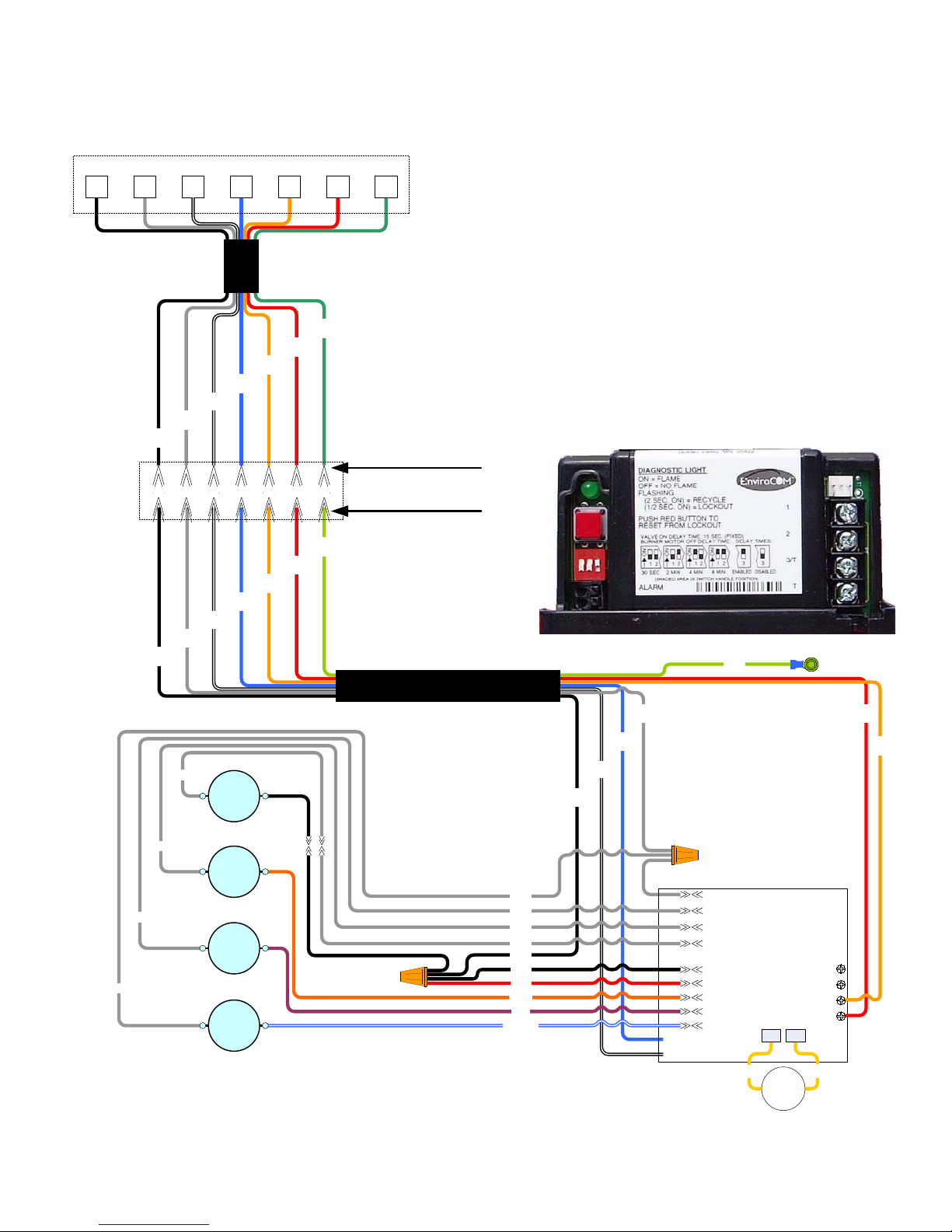
P
U
MAIN CONTROL PANEL TERMINAL STRIP
BURNER
CABLE
GRN
GND
RED
11
ORG
12
BLU
10
WHT/BLK
25
WHT
2
BLK
13
E
R
E
H
T
A
S
F
A
E
I
D
E
S
E
L
B
R
U
N
GND11121025213
SEVEN PIN CONNECTOR (FEMALE)
T
E
Y
R
O
C
W
T
N
O
R
L
S
I
I
R
G
N
BURNER CONTROL
(P/N P100-206)
A B C D E F G
WHT/BLK
25
WHT
2
BLK
13
WHT
WHT
WHT
WHT
INLINE
FUEL
HEATER
BURNER
MOTOR
FUEL
SHUT-OFF
VALVE
IGNITION
BLU
10
ORG
12
RED
SEVEN PIN CONNECTOR (MALE)
GRN
GND
11
GRN
BURNER
PIGTAIL
CABLE
WHT
WHT
WHT
WHT
BLK
BLK
RED
ORG
VIO
BLU/WHT
BLK
13
WHT/BLK
25
BLU
WHT
2
10
ALARM
ALARM
GND
BURNER CONTROL
(P/N P100-206)
L-2
L-2
L-2
L-2
L-1
LIMIT
BURNER
VALVE
IGN
YEL
CAD
CELL
RED
11
ORG
12
1
2
3T
T
C-C+
YEL
A - 10
© 2006 Ground Heaters, Inc.
V. 2, Rev. 09/01/06
Page 62
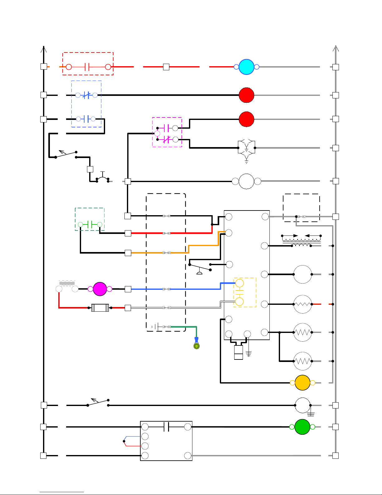
BLK
PUREHEAT WIRING SCHEMATIC
(SHEET 3)
1
CIRCUIT 1 WITH NP/LP BURNER
N
1
1
C H
ORG
4
RED
4
CR1-1
1
BLK
78
1
21
68
13
CR3
NO
COM
NC
1
BLK
BLK
BURNER SW.
TS1
14
13
BLK1414
200 º F.
MANUAL RESET
BI-METAL DISC
WHT
13
BURNER
CABLE
13
C
R
2
13
6 8
11
12
11
12
11
1
12
PIN-A (BLK)
PIN-F (RED)
PIN-E (ORG)
TX-1
120V
12V
127
24
COIL COIL
25
12VAC
12VDC
CR3
FU-2
10
10
25
25
10
25
10
PIN-D (BLU)
PIN C (WHT/BLK)
3AG 5.0 SB
PIN-G (GRN)
4
RED
20
27
3
13
13
11
12
AIR PRESS SW.
10
25
0 1
CR-1
LOW LEVEL FAULT LAMP
R
BURNER FAULT LAMP
R
RECEPTACLE
HOUR METER
-+
5
6
7
ALARM
3
COM
NO
L2
10
BURNER
CONTROL
4
CR5
8
BURNER
CABLE
PIN-B (WHT)
IGN. TRANS.
BURNER MOTOR
5.6
FLA.
PILOT GAS VALVE
MAIN GAS VALVE
WHT
WHT
WHT
WHT
WHT
WHT
WHT
RED
2
2
2
2
2
2
2
2
2
2
2
2
LOW LEVEL
CAB LIGHT SW.
1
BLK
1
1 WHT
1
THERMOCOUPLE,
TYPE T
1
BLK
V. 2, Rev. 09/01/06
BLU
RED
14
15
17
DIGITAL
18
TEMPERATURE
CONTROL
5
6
© 2006 Ground Heaters, Inc.
BURNER
GROUND
9
GF
WHT
AUX GAS VALVE
IR FLAME SENSOR
COIL COIL
CR5
5
CAB LIGHT
W
WHT
WHT
WHT
2
2
22
01 CR2
2BLK
2
WHT
2
A - 11
Page 63
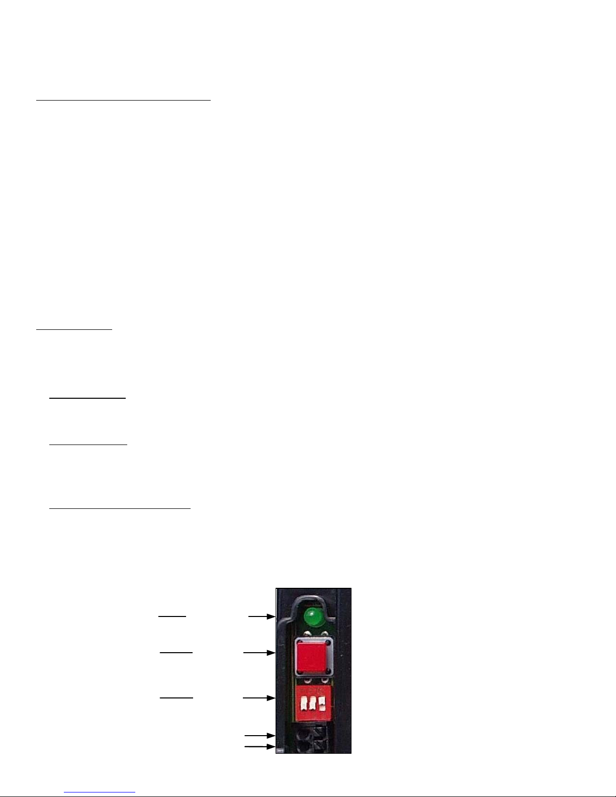
PUREHEAT DIESEL BURNER CONTROL
SEQUENCE OF OPERATION AND LOCKOUT
NORMAL SEQUENCE OF OPERATION:
Assuming a normal power up has been completed per Section 2 of this manual, the BURNER Switch is turned ON, the In-Line
Fuel Heater is energized and begins to warm the fuel in the Nozzle Assembly Tube. With a demand for heat, outpu t contacts 14
& 15 of the Temperature Control (TC) will close completing a circuit from L1 to the Burner Control Relay Coil (CR-2). Burner
Control Relay (CR-2) normally open contacts 6 - 8 will CLOSE completing a circuit between 3T & T of the burner control.
The Burner Control initiates a 5 second self diagnostic test followed by a non-adjustable 15 second valve on-delay period called
Pre-purge. During the Pre-purge cycle, both the Ignition Transformer and Burner Blower Motor are energized but fuel is not
allowed to flow past the Fuel Shut-off Valve. Once the pre-purge cycle is complete, the Fuel Shut-off Valve Solenoid Coil is
energized by the Burner Control and fuel flow is initiated to the Burner Nozzle. Once fuel flow has begun, a 10 second trial for
ignition period begins. During trial for ignition, the Ignition Transformer remains energized fo r an additional 10 seconds, this is
known as ignition carryover. Once flame is established and proven by a Cad Cell resistance value of more than 300 but less
than 1600 Ohms, the Ignition and the ten second trial for ignition time has ela psed, the Ignition Transformer is de-energized for
the duration of the heating cycle. Once the demand for heat has been satisfied, output contacts 14 & 15 of the TC OPEN
breaking the circuit to Burner Control Relay Coil CR-2. The now de-energized relay will OPEN Relay CR-2 contacts 6 - 8
breaking the circuit at 3T to T of the Burner Control. The Burner Control will shut off the fu el supply to the burner nozzle by deenergizing the Fuel Shut-off Valve Solenoid coil. The Burner Blower Motor will continue to run for 15 seconds (post-purge
cycle). The amount of time allowed for pre-purge depends on the Off-delay Dip Switch setting. Ground Heaters, Inc.
recommends the factory setting of 15 seconds off-delay. Several delay settings are available as detailed on the front of the
burner control.
BURNER FAULT:
If the Cad Cell senses an absent or unstable flame at any time during the heating cycle, the Burner Control immediately shuts
down all Burner functions and enters one of three protective modes (BURNER FAULT). BURNER FAULT is identified by the
Diagnostic Light (see photo below) and indicated by illuminating the BURNER FAULT Light (main control panel) simultaneously.
The three BURNER FAULT or Lockout modes are described in detail below.
1. RECYCLE MODE
:
The DIAGNOSTIC Light will flash in two second intervals while attempting three automatic restarts. If the flame fails after three
successive attempts, the control will enter Lockout Mode.
2. LOCKOUT MODE
:
The DIAGNOSTIC Light will flash in ½ second intervals. The RESET button must be momentarily pressed to clear the Lockout
and attempt a Burner restart. After the third attempt to manually clear the Lockout mode, the Burner Control will begin
Restricted Lockout Mode.
3. RESTRICTED LOCKOUT MODE
:
The DIAGNOSTIC Light will flash in ½ second intervals. The RESET button must be pressed and held until the DIAGNOSTIC
Light comes on momentarily and then goes out. The Burner Control will return to Restricted Lockout Mode with each flame
failure until one successful heating cycle has occurred.
DIAGNOSTIC LIGHT
RESET BUTTON
OFF DELAY DIP
SWITCHES
ALARM
(BURNER FAULT)
CONNECTIONS
A - 12
© 2006 Ground Heaters, Inc.
V. 2, Rev. 09/01/06
Page 64
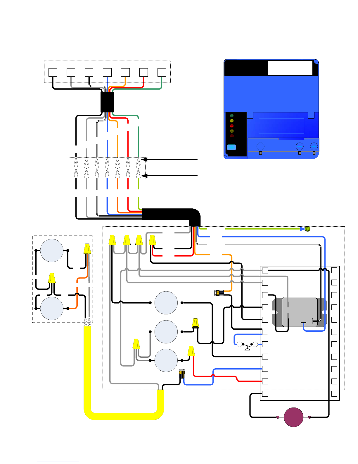
PUREHEAT SAFETY CONTROLS
NG/LP BURNER WIRING DIAGRAM
GAS TRAIN
MAIN
GAS
VALVE
MAIN CONTROL PANEL TERMINAL STRIP
BURNER
CABLE
GRN
GND
RED
11
ORG
12
BLU
10
WHT/BLK
25
WHT
2
BLK
13
A B C D E F G
RED
ORG
BLK13WHT2WHT/BLK
BLU
12
10
25
GRN
11
GND
GND11121025213
SEVEN PIN CONNECTOR (FEMALE)
SEVEN PIN CONNECTOR (MALE)
BURNER
PIGTAIL CABLE
WHT 2
BLK 13
RED 11
GRN - GND
WHT/BLK 25
BLU 10
ORG 12
Honeywell
NG/LP BURNER
CONTROL
P/N P100-338
POWER
PILOT
FLAME
MAIN
ALARM
RESET
BURNER CONTROL
Honeywell
Honeywell
Honeywell
Honeywell
S
S
BLK
BLK
AUX
GAS
VALVE
BLK
BLK
ORG WHT
2 PIN GAS TRAIN CABLE
PILOT GAS
VALVE
BLOWER
MOTOR
IGNITION
TRANS
BURNER
CONTROL
SUB-BASE
AIR PRESSURE
2 3
G
L2
3
4
5
6
7
8
9
10
COIL
COIL
COM
NO
l2
13
14
15
16
17
18
19
20
21
GAS BURNER
F
CONTROL
P/N P100-338
UV
FLAME
SENSOR
22
V. 2, Rev. 09/01/06
© 2006 Ground Heaters, Inc.
A - 13
Page 65
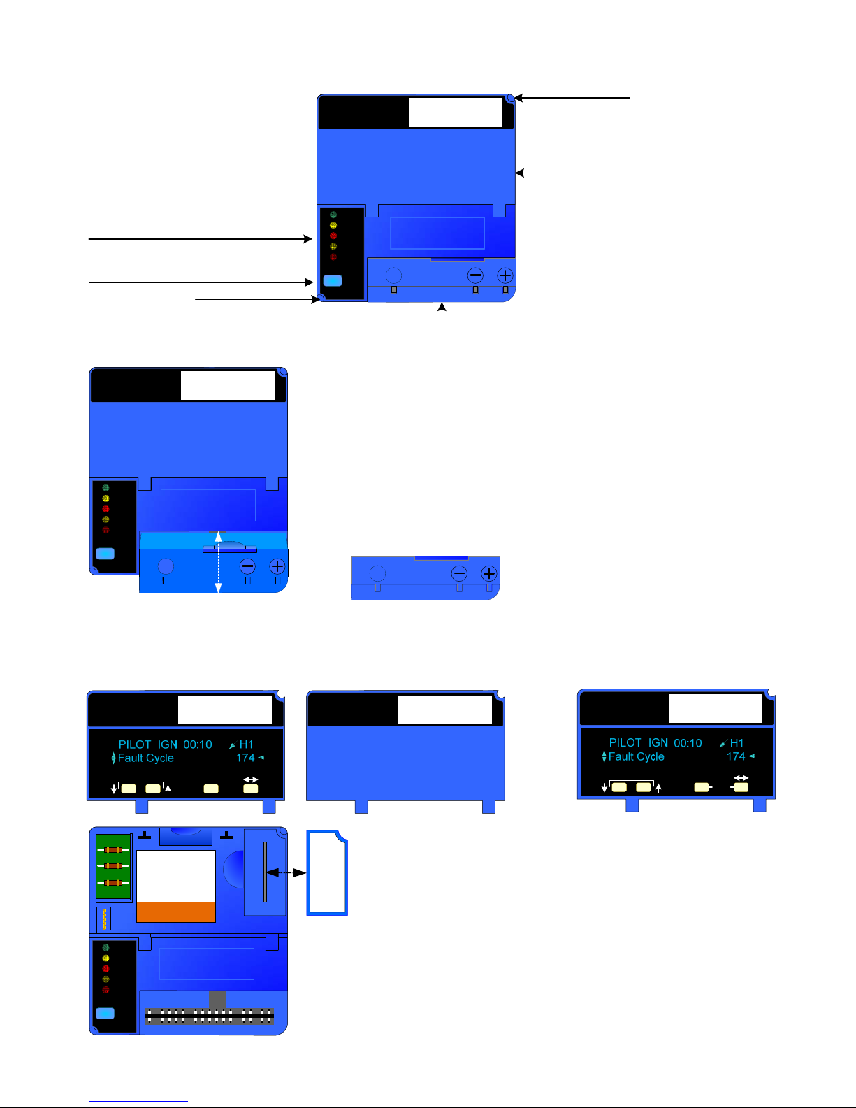
PUREHEAT SAFETY CONTROLS
BURNER CONTROL OVERVIEW
Status Panel: Indicator lights
illuminate to show the Burner
Operation Status.
Reset Button: Press and release
to clear Burner ALARM condition
Mounting Screw
Honeywel
l
POWER
PILOT
FLAME
MAIN
ALARM
RESET
BURNER CONTROL
Honeywell
Honeywell
Honeywell
Honeywell
S
S
Flame Amplifier
Mounting Screw
Dust Cover: Remove to access the Purge
Timer or to mount the S7800 Keyboard Display
Module (Available through Honeywell, Inc.)
Honeywel
l
BURNER CONTROL
Flame Amplifier (*p/n P100-368): Boosts the
signal from the Ultra Violet (UV) Flame
Detector, the Flame Detector monitors the Pilot
Flame and allows Main Gas Valve operation
provided the Pilot Flame remains stable. To
POWER
PILOT
FLAME
MAIN
ALARM
RESET
Honeywell
Honeywell
Honeywell
Honeywell
S
S
remove the Flame Amplifier, carefully pry the
Amplifier away from the Main Control using the
slot provided.
S
S
Dust Cover: Removed to access the Purge Timer or to mount the S7800
Keyboard Display Module.
Honeywel
l
SCROLL MODE
BURNER CONTROL
SAVE
Honeywel
l
BURNER CONTROL
Honeywel
l
SCROLL MODE
BURNER CONTROL
SAVE
POWER
PILOT
FLAME
MAIN
ALARM
RESET
Honeywell
Honeywell
Honeywell
Honeywell
A – 13a
Purge Timer
(p/n P100-369):
A fixed 30 second timer
for the Pre-Purge cycle
Honeywell
ST7800 A 1039
30 SECONDS
of the Burner.
© 2006 Ground Heaters, Inc.
S7800A KEYBOARD DISPLAY MODULE:
The S7800 Keyboard Display Module (shown
powered) is a tool to aid in the diagnosis of
Burner malfunctions and is available through
Honeywell, Inc.
V. 2, Rev. 09/01/06
Page 66
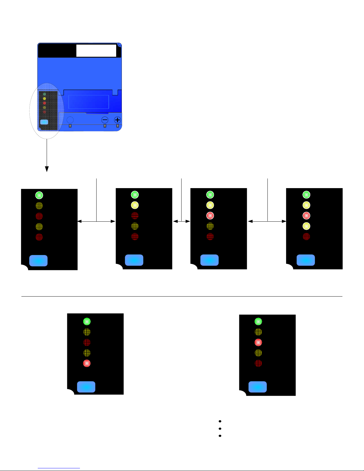
PUREHEAT SAFETY CONTROLS
SEQUENCE OF OPERATION
Honeywel
BURNER CONTROL
l
POWER
PILOT
FLAME
MAIN
ALARM
RESET
Honeywell
Honeywell
Honeywell
Honeywell
S
S
30 SECOND
PRE-PURGE
1-3 SECONDS
15 SECOND
FLAME CHECK
1234
POWER
PILOT
FLAME
MAIN
ALARM
POWER
PILOT
FLAME
MAIN
ALARM
POWER
PILOT
FLAME
MAIN
ALARM
POWER
PILOT
FLAME
MAIN
ALARM
RESET
BURNER SWITCH ON
BURNER CONTROL IS IN ALARM MODE,
PRESS AND RELEASE RESET BUTTON
POWER
PILOT
FLAME
MAIN
ALARM
RESET
RESET
PILOT GAS VALVE
POWERED
RESET
PILOT FLAME
DETECTED
POWER
PILOT
FLAME
MAIN
ALARM
RESET
FLAME INDICATOR LAMP ILLUMINATES
AFTER BURNER SWITCH IS TURNED ON
BUT THE BURNER DOES NOT START:
FLAME AMPLIFIER FAILURE
UV FLAME SENSOR FAILURE
MOISTURE IN BURNER CONTROL
RESET
MAIN GAS VALVES
POWERED, NORMAL HEAT
CYCLE IN PROGRESS
V. 2, Rev. 09/01/06
© 2006 Ground Heaters, Inc.
A – 13b
Page 67
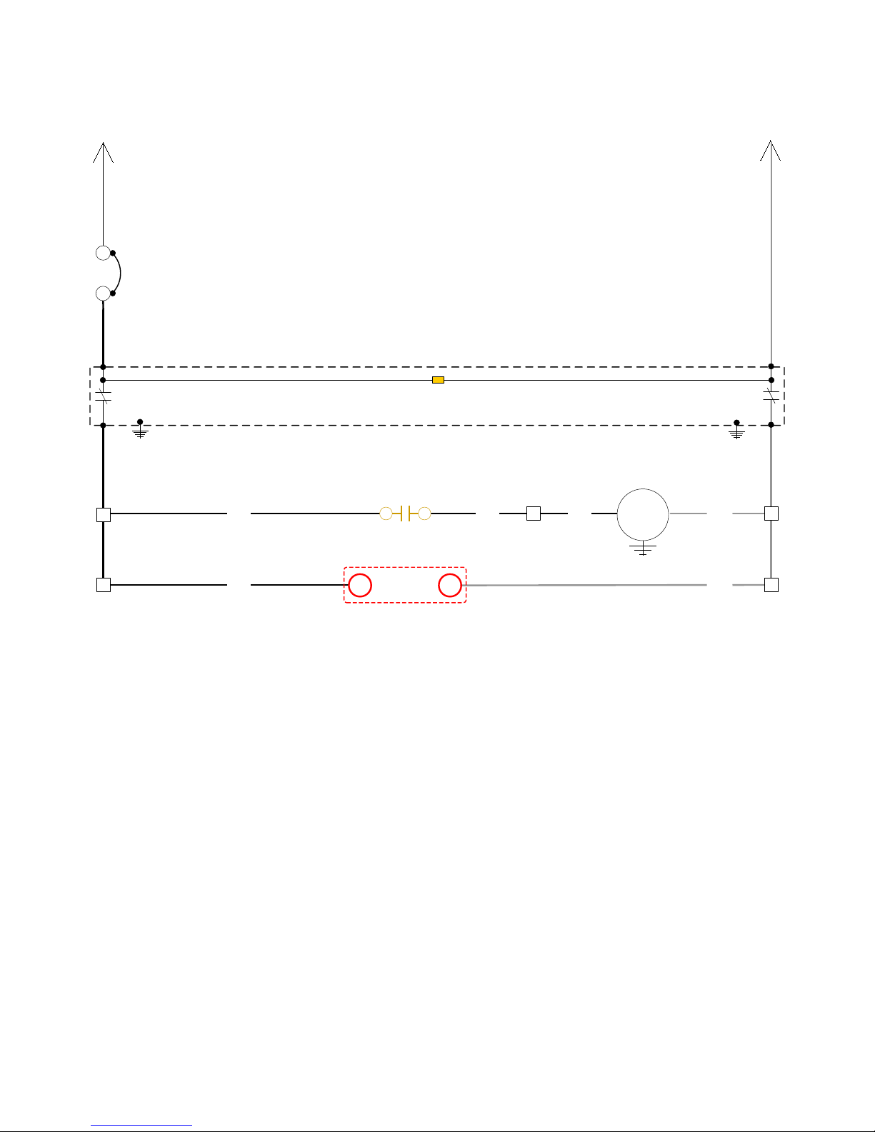
PUREHEAT WIRING SCHEMATIC
CIRCUIT 2
+120VAC
L2
LINE
CB-2
20A
LOAD
L4
LINE
LOAD
26
26
GFCI-2
26
BLK
2
CR-4
GROUND FAULT
INDICATOR LAMP
3
16
BLK
16
PUMP MOTOR
16
BLK
15.8A 1.5 HP
PUMP
GFCI-2
17
WHT
N2
LINE
LOAD
17
17
26
26
BLK
LOW LEVEL
LOGICH N
17
WHT
17
A - 14
© 2006 Ground Heaters, Inc.
V. 2, Rev. 09/01/06
Page 68
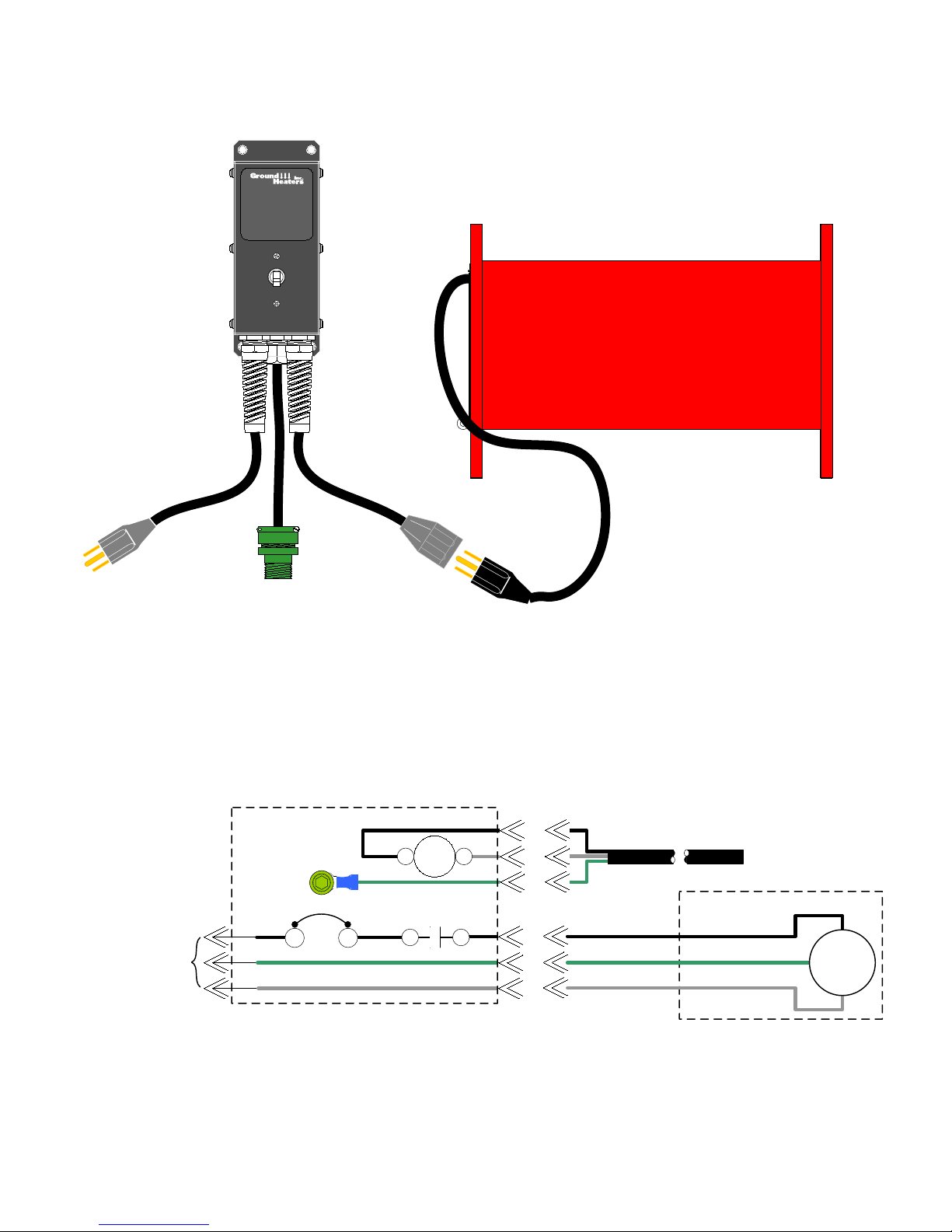
PUREHEAT SCHEMATIC – AUXILIARY PUMP PANEL
(P/N A109-199)
Auxiliary
Pump
Panel
o
BOOSTER PUMP
20A Power IN
BOOSTER PUMP AND AUXILIARY PUMP PANEL INTERNAL SCHEMATIC
CONNECT TO:
120V 20A 60Hz POWER
SUPPLY
(GFCI PROTECTED)
Aux. Pump
Cable
AUX PUMP PANEL
L3
GND
N3
CB-3
20A
LINE LOAD
OUT TO
PUMP
CRX-1
5 6
CRX-1
11 12
2 3
AUX PUMP PANEL
CABLE CONNECTION
PIN A BLK
PIN B WHT
PIN C GRN
5
2
A
B
C
BOOSTER PUMP
CONNECTION
AUX PUMP CABLE
BOOSTER PUMP
BLK
93
GRN
WHT
N3
MTR1
V. 2, Rev. 09/01/06
© 2006 Ground Heaters, Inc.
A - 15
Page 69
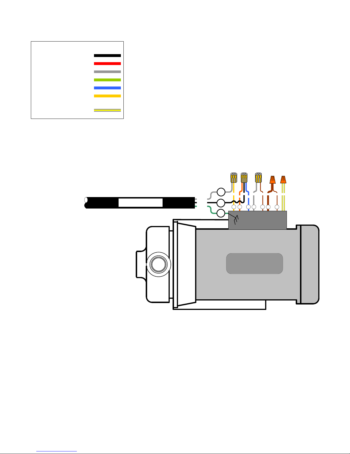
PUREHEAT CIRCULATION - BOOSTER PUMP MOTOR WIRING
WIRE COLORS
BLK = BLACK
RED = RED
WHT = WHITE
GRN = GREEN
BLU = BLUE
YEL = YELLOW
W/y = WHITE W/
YELLOW TRACE
PUMP CABLE
WHT
BLK
GRN
17
16
GND
YEL
4 13
ORG
BLK
WHT
BRN
BRN BRN
W/y
BLU
J2
YELLOW TRACE
JJ
CIRCULATION - BOOSTER PUMP ASSY.
1.5 HP 15.8 FLA 18.8 SFA
P/N M100-647
WHITE WITH
(X2)
A - 16
© 2006 Ground Heaters, Inc.
V. 2, Rev. 09/01/06
Page 70
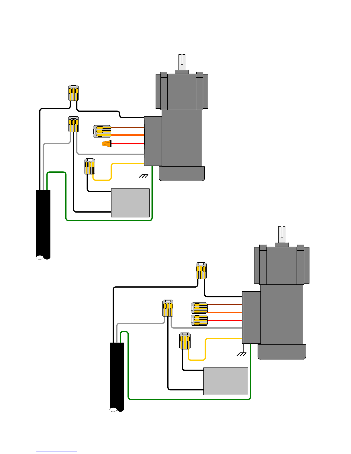
BLK
WHT
GND
PUREHEAT REWIND MOTOR WIRING
DAYTON
GEAR MOTOR
th
HP 120 v. 60 Hz
1/6
P/N E100-212
BLK
BRN
ORG
RED
WHT
YEL
BLK
BLK
CAPACITOR
10 µƒ
330V
BLK
WHT
BISON
GEAR MOTOR
th
HP 120 v. 60 Hz
1/6
P/N E100-212
BLK
BRN
ORG
RED
WHT
YEL
V. 2, Rev. 09/01/06
GND
© 2006 Ground Heaters, Inc.
BLK
BLK
CAPACITOR
10 µƒ
330V
A - 17
Page 71
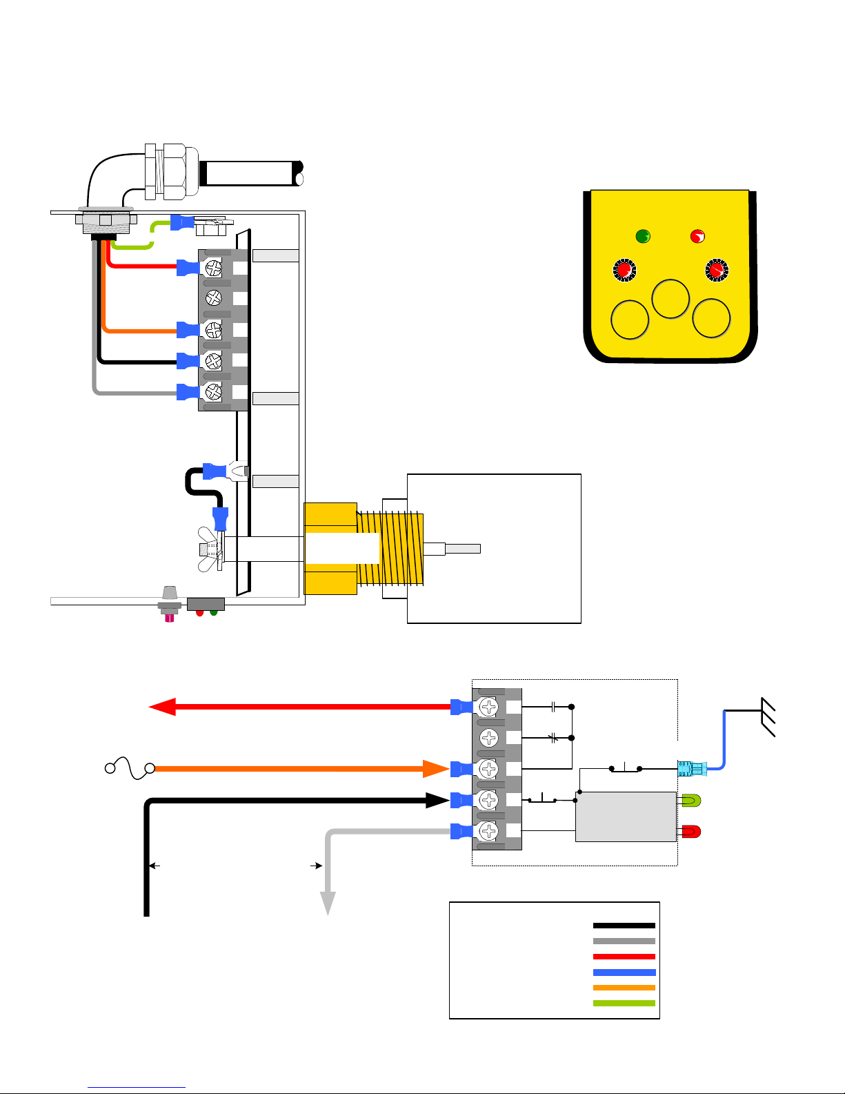
PUREHEAT SAFETY CONTROLS
LOW LEVEL SHUTDOWN DEVICE
(P/N E100-198)
NOTE: CONTROL IS SHOWN IN A NON-POWERED STATE
LOW LEVEL
LOW LEVEL SHUTDOWN DEVICE CONTROLS
AND INDICATOR LIGHTS LOCATION ON THE
BOTTOM OF THE DEVICE.
RED
4
ORG
1
BLK
26
WHT
17
GRN
BLK
POWER LOW WATER
TEST
RESET
B
W
C
H
N
REFER TO SECTION
5.2.1.2 FOR
DETAILED TESTING
INSTRUCTIONS
HYDRONIC
HEATER SHELL
LOW LEVEL
SENSOR
FUSE 3
2 AMP
TO RELAY COILS K-1 & K-2
110 VOLTS FROM CIRCUIT 1
110 VOLTS FROM CIRCUIT 2
LOW LEVEL DEVICE INTERNAL SCHEMATIC
RED
4
ORG
1
BLK
26
WHT
17
B
W
C
H
RESET
N
N.O.
N.C.
TEST
LOW LEVEL
LOGIC MODULE
PROBE
CONNECTION
WIRE COLORS
BLK = BLACK
WHT = WHITE
RED = RED
BLU = BLUE
ORG = ORANGE
GRN = GREEN
SENSOR
(PROBE)
GREEN LED
RED LED
A - 18
© 2006 Ground Heaters, Inc.
V. 2, Rev. 09/01/06
Page 72
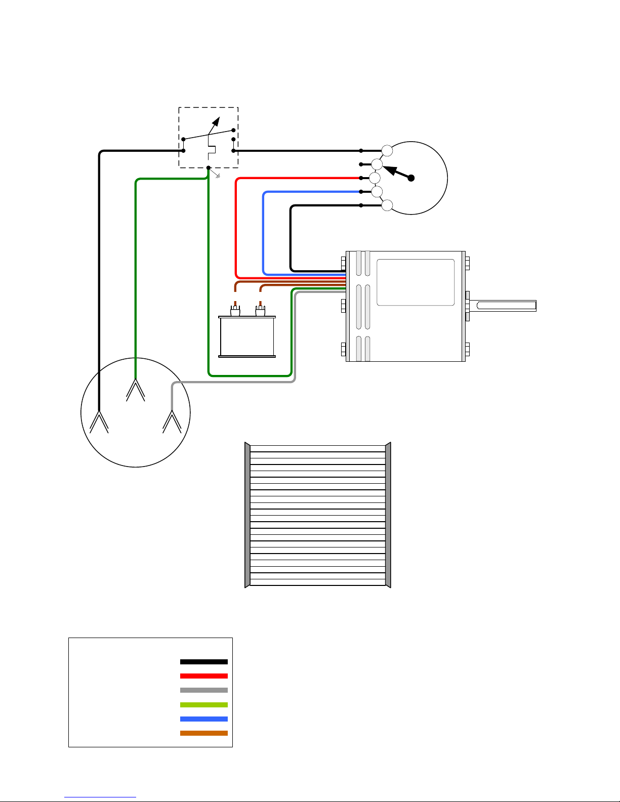
HX200 HEAT XCHANGER™ WIRING DIAGRAM
THERMOSTAT
P/N M100-740
ROTARY SWITCH
L-1 BLK T-1 BLK
OFF
RED LO
BLUE MEDIUM
BLK HI
BRN BRN
370V
15 mfd
P/N E100-646
P/N E100-334
1
2
3
4
5
BLOWER
MOTOR
E100-349
P/N E100-335
RECESSED PLUG
WIRE COLORS
BLK = BLACK
RED = RED
WHT = WHITE
GRN = GREEN
BLU = BLUE
BRN = BROWN
CAPACITOR
BLOWER WHEEL
P/N F109-008
V. 2, Rev. 09/01/06
© 2006 Ground Heaters, Inc.
A - 19
Page 73
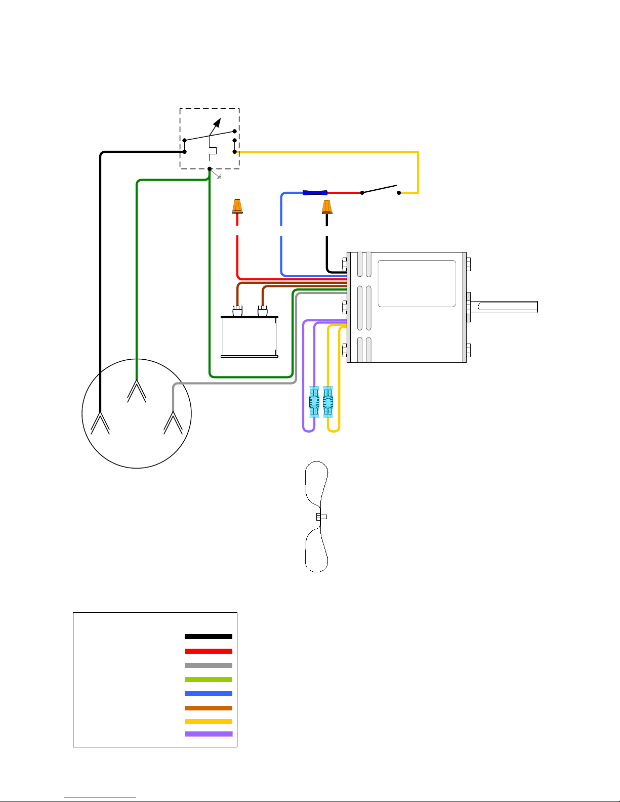
HX100 HEAT XCHANGER™ WIRING DIAGRAM
THERMOSTAT
P/N M100-773
L-1 BLK T-1 YEL
TOGGLE SWITCH
P/N E100-101
P/N E100-335
RECESSED PLUG
RED LO
370V
7.5 mfd
P/N M100-769
CAPACITOR
BLU MED
BLK HI
BLOWER
MOTOR
F109-167
WIRE COLORS
BLK = BLACK
RED = RED
WHT = WHITE
GRN = GREEN
BLU = BLUE
BRN = BROWN
YEL = YELLOW
PURP = PURPLE
A - 20
FAN BLADE M100-772
© 2006 Ground Heaters, Inc.
V. 2, Rev. 09/01/06
Page 74
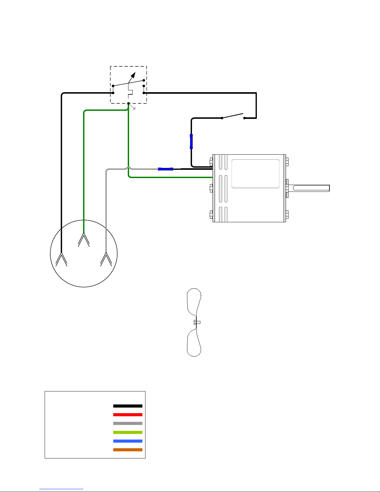
HX50 HEAT XCHANGER™ WIRING DIAGRAM
THERMOSTAT
P/N M100-773
L-1 BLK T-1 BLK
TOGGLE SWITCH
P/N E100-101
BLK
BLOWER
MOTOR
E100-378
P/N E100-335
RECESSED PLUG
WIRE COLORS
BLK = BLACK
RED = RED
WHT = WHITE
GRN = GREEN
BLU = BLUE
BRN = BROWN
FAN BLADE M100-771
V. 2, Rev. 09/01/06
© 2006 Ground Heaters, Inc.
A - 21
Page 75
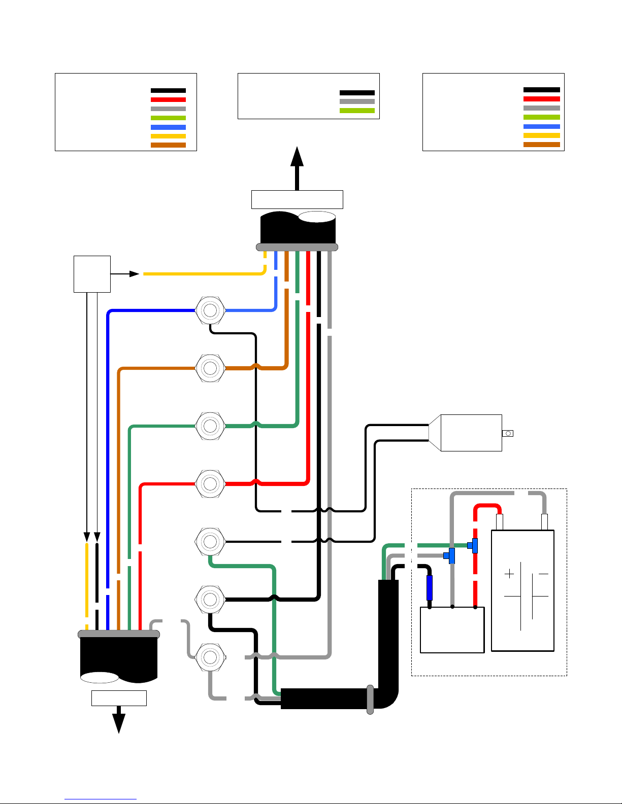
PUREHEAT TRAILER JUNCTION BOX AND BATTERY WIRING
BLK = BLACK -NOT USED
TRAILER WIRE COLORS
RED = RED - LEFT TURN
WHT = WHITE -NEGATIVE/GROUND
GRN = GREEN - RUNNING LIGHTS
BLU = BLUE - BRAKES
YEL = YELLOW -NOT USED
BRN = BROWN- RIGHT TURN
NOT
USED
BLU.
BRN.
BATTERY WIRE COLORS
BLK = BLACK -VEHICLE 12 VOLTS DC
WHT = WHITE -NEGATIVE/GROUND
GRN = GREEN - TRAILER BATTERY
TOW VEHICLE
YEL
BLU
BRN
GRN
RED
BLK
WHT
7-WAY PLUG WIRING COLORS
BLK = BLACK -VEHICLE 12 VOLTS DC
RED = RED -LEFT TURN
WHT = WHITE -NEGATIVE/GROUND
GRN = GREEN - RUNNING LIGHTS
BLU = BLUE -BRAKES
YEL = YELLOW -NOT USED
BRN = BROWN - RIGHT TURN
BLU
BLK
YEL
TRAILER
BRN
GRN
RED
WHT
GRN.
RED
YEL.
BLK.
WHT.
WHT
WHT
BLK
BLK
BATT CABLE
GRN
WHT
BLK
BATTERY
CHARGER
BREAK-AWAY
SWITCH
RED
RED
BATTERY BOX
WHT
+ -
BATTERY
12 Volt DC
A - 22
© 2006 Ground Heaters, Inc.
V. 2, Rev. 09/01/06
Page 76
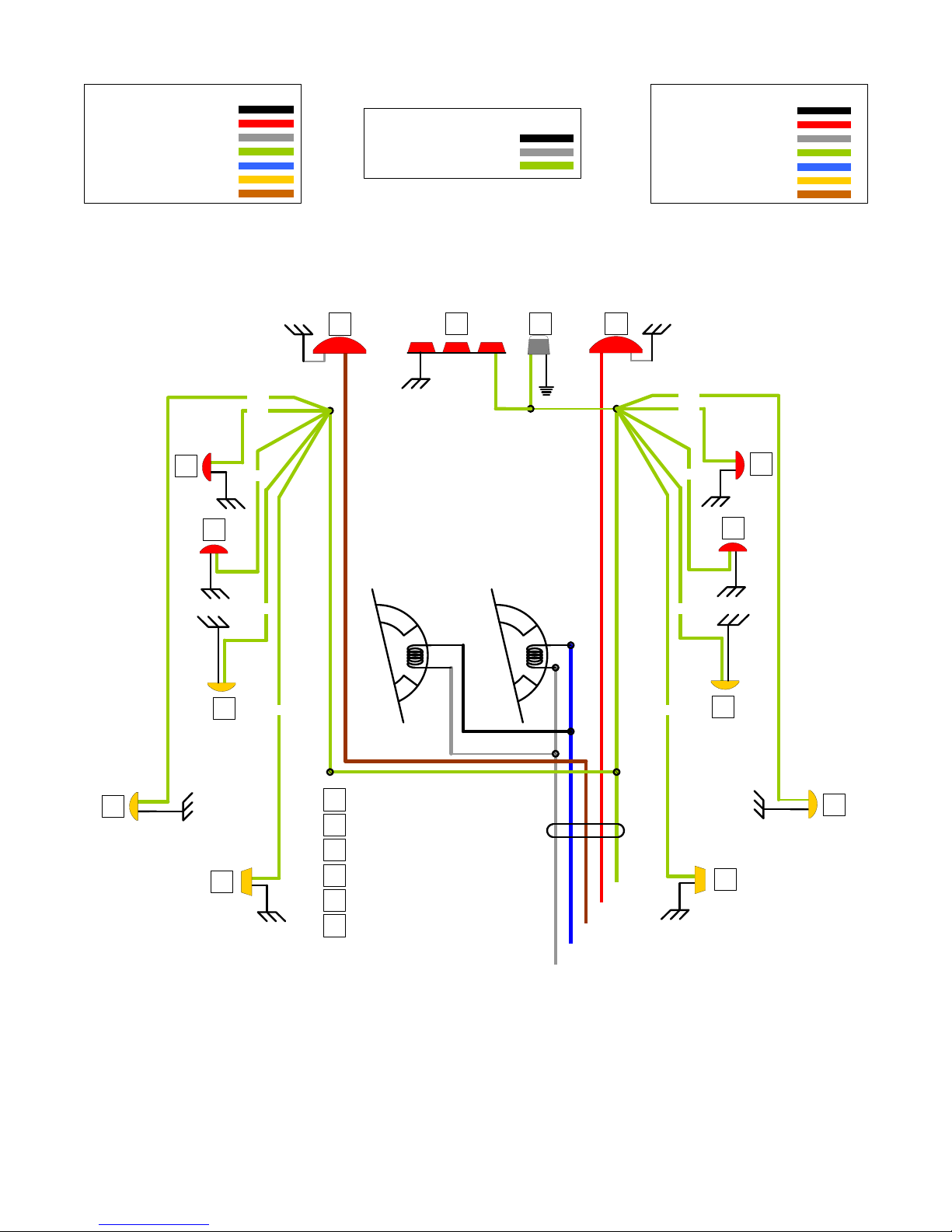
PUREHEAT TRAILER WIRING
7-WAY PLUG WIRING COLORS
BLK = BLACK -VEHICLE 12 VOLTS DC
RED = RED - LEFT TURN
WHT = WHITE -NEGATIVE/GROUND
GRN = GREEN - RUNNING LIGHTS
BLU = BLUE - BRAKES
YEL = YELLOW -NOT USED
BRN = BROWN - RIGHT TURN
A
A
GRN
GRN
GRN
BLK = BLACK -VEHICLE 12 VOLTS DC
WHT = WHITE -NEGATIVE/GROUND
GRN = GREEN - TRAILER BATTERY
C
BATTERY WIRE COLORS
ED C
BLK = BLACK -NOT USED
RED = RED - LEFT TURN
WHT = WHITE -NEGATIVE/GROUND
GRN = GREEN - RUNNING LIGHTS
BLU = BLUE - BRAKES
YEL = YELLOW -NOT USED
BRN = BROWN- RIGHT TURN
TRAILER WIRE COLORS
GRN
GRN
GRN
A
A
ELECTRIC BRAKES
GRN
B
B
F
GRN
LIGHT, 2 BULB RED (P/N E100-131)
A
LIGHT, 2 BULB AMBER (P/N E100-132)
B
LIGHT, STOP-TURN (P/N E100-342)
C
3 LIGHT COMBO (P/N E100-022)
D
LICENSE PLATE LIGHT (P/N E100-491)
E
MINI LIGHT, AMBER (P/N E100-133)
F
GRN
RED
BRN
BLU
WHT
GRN
GRN
B
B
F
V. 2, Rev. 09/01/06
© 2006 Ground Heaters, Inc.
A - 23
Page 77
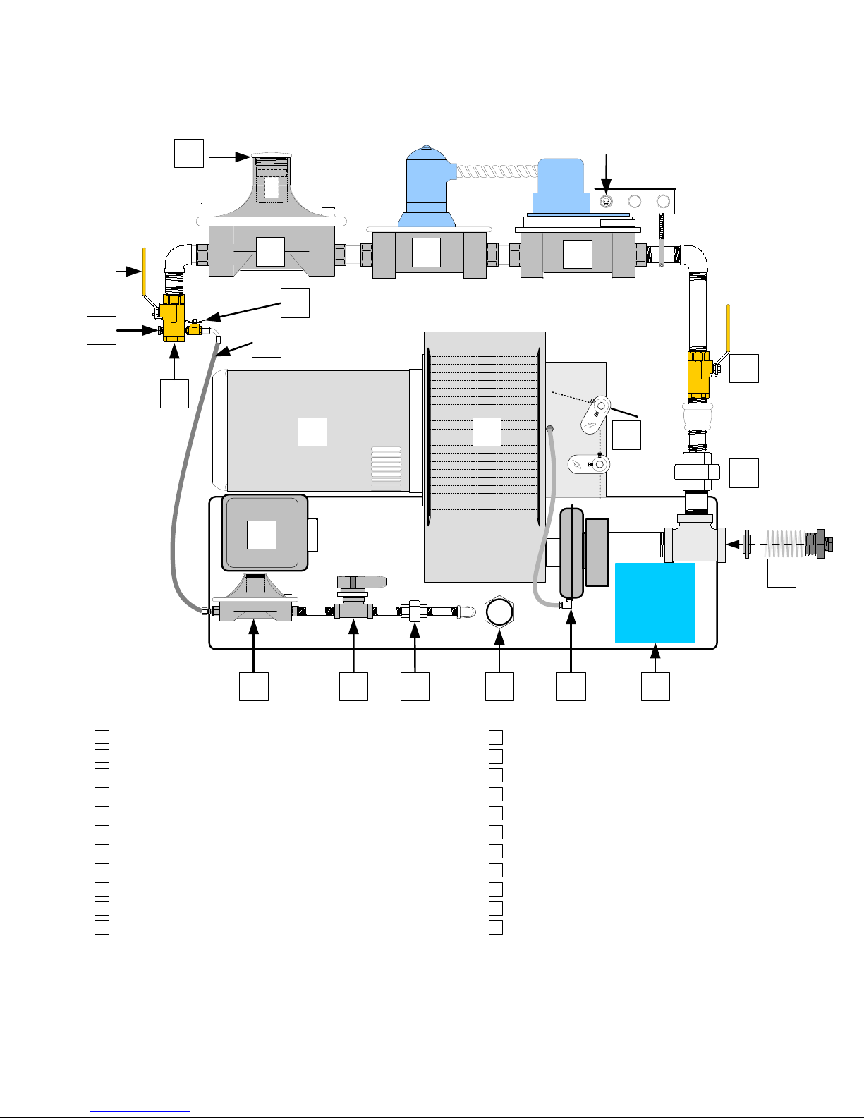
PUREHEAT NG/LP BURNER COMPONENT IDENTIFICATION
(P/N P100-673)
F
G
H
A
W
B
I
E
C
D
J
M
K
L
N
O
UV
A
REGULATOR DUST CAP
B
MANIFOLD GAS PRESSURE REGULATOR (P/N P100-342)
C
MAIN GAS VALVE (P/N P100-340)
D
AUX GAS VALVE (P/N P100-341)
E
1/16" MALE PIN PLUG (P/N100-341)
F
GAS SUPPLY INLET VALVE
G
GAS SUPPLY PRESSURE TEST PORT
H
MAIN GAS SUPPLY CONNECTION POINT
I
PILOT GAS LINE (P/N F100-130)
J
PILOT GAS SUPPLY VALVE
K
BURNER BLOWER MOTOR (P/N P100-333)
HONEYWELL
POWER
PILOT
FLAME
MAIN
ALARM
RESET
T
BURNER BLOWER WHEEL (P/N P100-334)
L
MANIFOLD GAS SHUT-OFF VALVE
M
AIR DAMPERS
N
GAS TRAIN UNION
O
PRESSURE TEST PORT w/ 9/16" ORIFICE & SPRING
P
BURNER CONTROL (P/N P100-338)
Q
AIR PROVING PRESSURE SWITCH (P/N P100-335)
R
I.R. PILOT FLAME SENSOR (P/N P100-354)
S
T
PILOT GAS TRAIN UNION
U
PILOT GAS VALVE (P/N P100-353)
V
PILOT GAS REGULATOR (P/N P100-336)
RS
Q
P
A - 24
© 2006 Ground Heaters, Inc.
V. 2, Rev. 09/01/06
Page 78
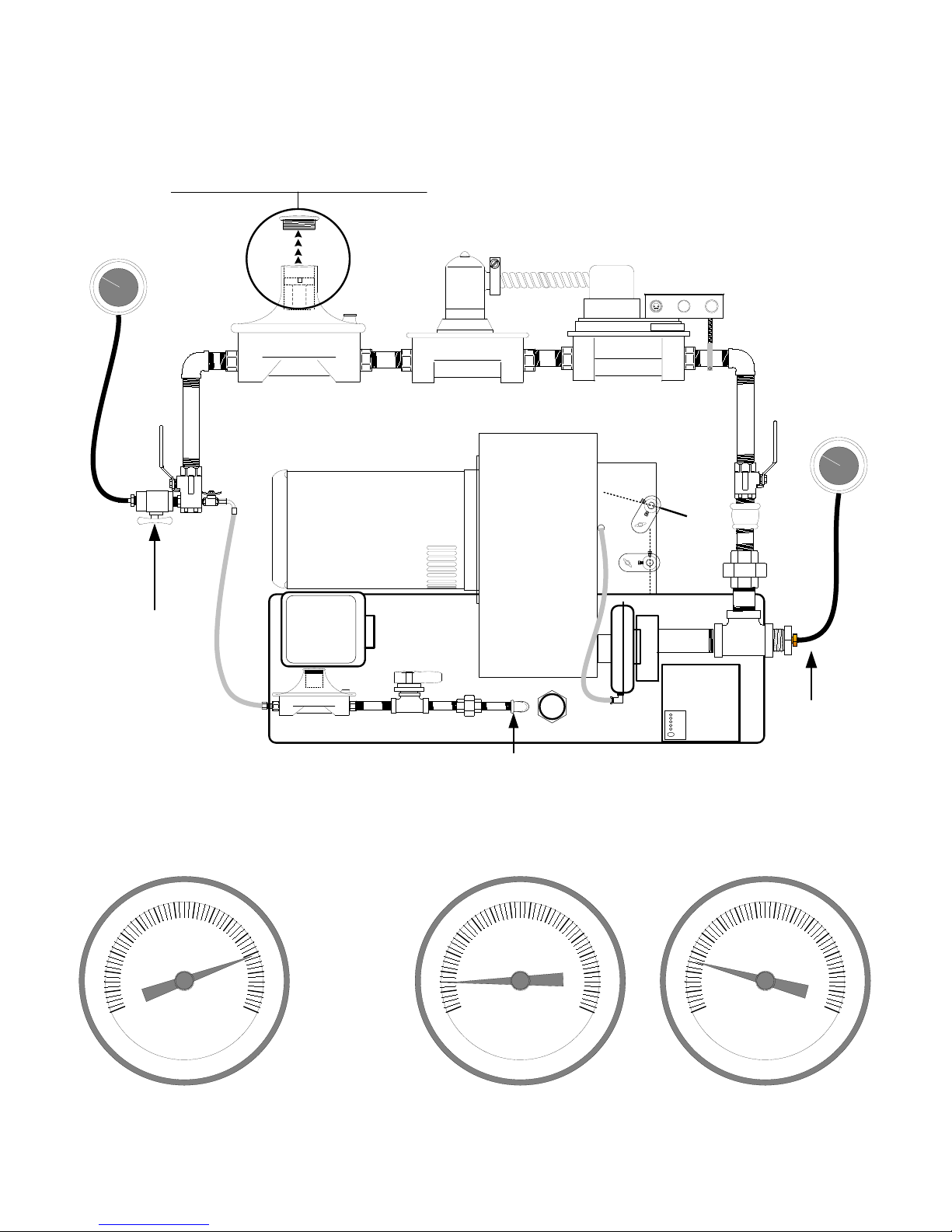
PUREHEAT NG/LP BURNER (P/N P100-673)
GAS PRESSURE CHECKING AND ADJUSTING
REMOVE THE GAS REGULATOR ADJUSTMENT COVER.
INSERT A SCREWDRIVER INTO THE ADJUSTMENT STEM.
TURN CLOCKWISE TO INCREASE PRESSURE.
TURN COUNTER CLOCKWISE TO DECREASE PRESSURE.
INSTALL A PETCOCK AND 0-30"
MANOMETER ADAPTER
FITTING IN THE PLACE OF THE
SUPPLY PRESSURE TAP PLUG.
SUPPLY GAS PRESSURE FOR
LP/NG IS 5 - 14"
8
7
6
5
4
3
2
1
0
Inches Water Column
HONEYWELL
POWER
PILOT GAS PRESSURE TAP
PILOT GAS PRESSUREIS PRE-SET TO 4.0 in WC
PILOT
FLAME
MAIN
ALARM
RESET
REMOVE THE PIPE PLUG AND
CONNECT A 0-15" (LOW
PRESSURE) MANOMETER
HERE TO READ MANIFOLD
PRESSURE
USE A MANOMETER TO MEASURE GAS PRESSURE
8
9
1
0
1
1
1
2
13
1
4
1
5
4
3
2
1
0
7
6
5
Inches Water Column
9
1
0
1
1
1
2
13
1
4
15
5
4
3
2
1
0
Inches Water Column
8
7
6
9
1
0
1
1
1
2
13
1
4
15
GAS SUPPLY PRESSURE
5 in WC MINIMUM
14 in WC MAXIMUM
V. 2, Rev. 09/01/06
LP 1.4-1.6 in. WC MAX
© 2006 Ground Heaters, Inc.
NG 2.5-3.0 in. WC MAX
GAS MANIFOLD PRESSURE
A - 25
Page 79
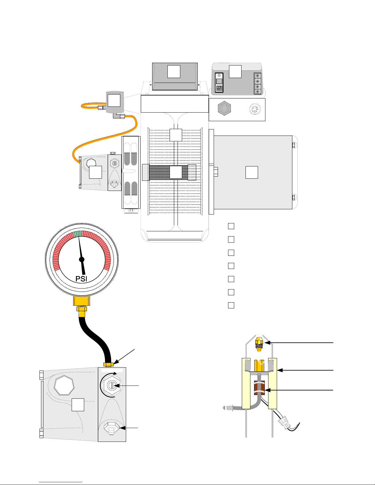
PUREHEAT DIESEL BURNER COMPONENT IDENTIFICATION
(P/N P100-690)
C
ALARM
ALARM
T
T
A
B
BECKETT
CF 800
E
D
150
1
7
5
2
1
0
0
1
5
7
0
5
25
0
5
2
0
0
2
2
5
2
5
0
275
3
0
0
0 – 300 PSI TEST GAUGE
(P/N P100-072)
F
A
B
C
D
E
F
G
FUEL SHUT OFF VALVE (P/N P100-306)
IGNITION TRANSFORMER (P/N P100-355)
BURNER CONTROL (P/N P100-206)
FUEL PUMP (P/N P100-359)
BLOWER WHEEL (P/N P100-356)
FUEL PUMP DRIVE COUPLER (P/N P100-273
INCREASE
S
A - 26
FUEL PRESSURE
TEST PORT
FUEL PRESSURE
ADJUSTING SCREW
FUEL SYSTEM
BLEEDER PORT
© 2006 Ground Heaters, Inc.
G
BURNER MOTOR (P/N P100-356)
BURNER NOZZLE
REPLACEMENT KIT
INLINE FUEL HEATER
NOZZLE ASSEMBLY
5.0 60 º A
(P/N P100-408)
ELECTRODE
(P/N P100-307)
(P/N P100-251)
V. 2, Rev. 09/01/06
Page 80
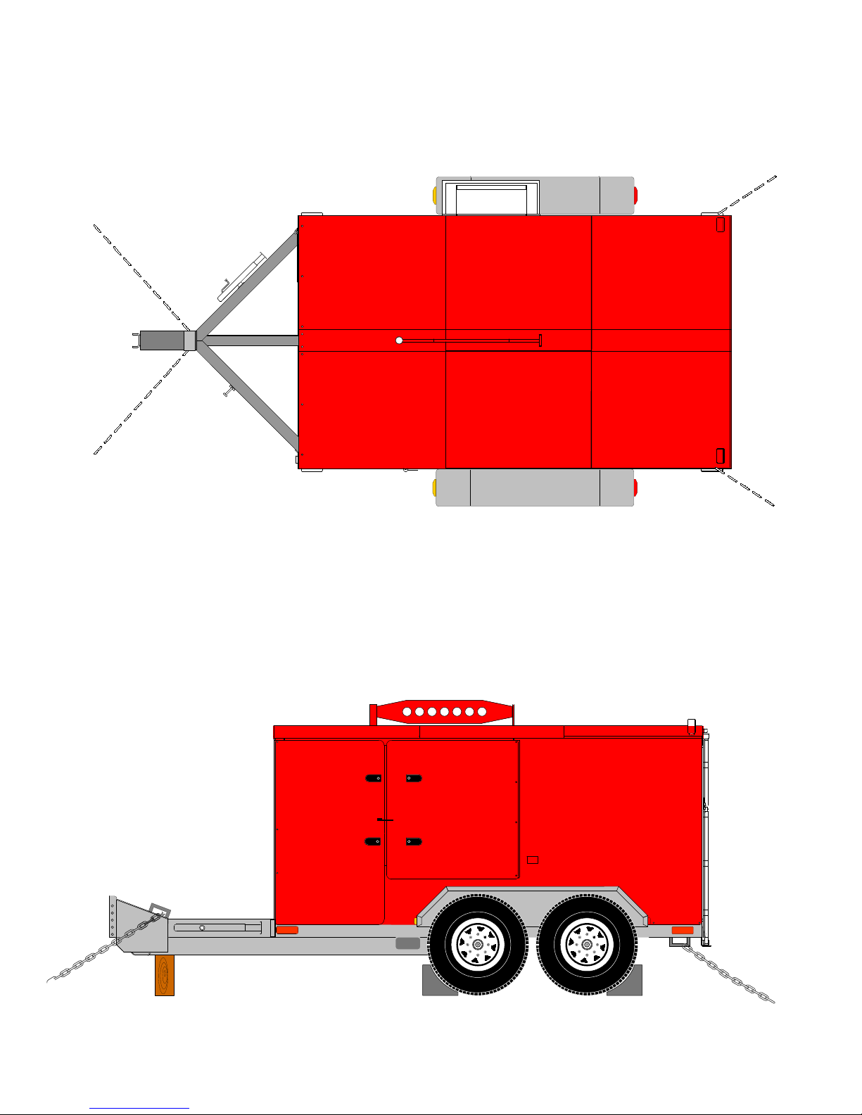
SUGGESTED METHOD FOR SECURING THE PUREHEAT ONTO A TRUCK BED
0
0
0
0
0
0
0
0
0
0
0
0
0
0
0
0
0
0
0
0
0
0
0
0
0
0
0
0
0
0
0
0
0
0
0
0
0
0
0
0
0
0
0
0
0
0
0
0
0
0
0
0
0
0
0
0
V. 2, Rev. 09/01/06
© 2006 Ground Heaters, Inc.
A - 27
Page 81
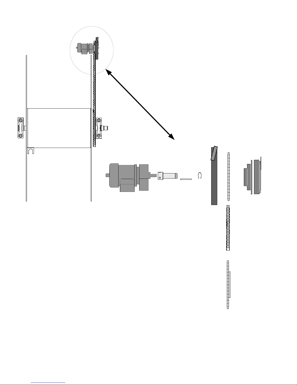
PUREHEAT HOSE REWIND PARTS IDENTIFICATION
E
F
A
B
D
C
G
GEAR MOTOR (P/N E100-212)
A
MOTOR SHAFT ADAPTER (P/N F102-026)
B
KEY, ¼ X ¼ X 1¾ (P/N M100-730)
C
RETAINING RING (P/N M100-707)
D
BRAKE ASSEMBLY (P/N A103-205)
E
CLUTCH DRIVE SPROCKET (P/N F109-041)
F
12 VOLT CLUTCH (P/N M100-108)
G
ROLLER CHAIN, #35, 231 PITCHES (P/N M100-372)
H
DRIVE SPROCKET (P/N M100-659)
I
H
I
A - 28
© 2006 Ground Heaters, Inc.
V. 2, Rev. 09/01/06
Page 82
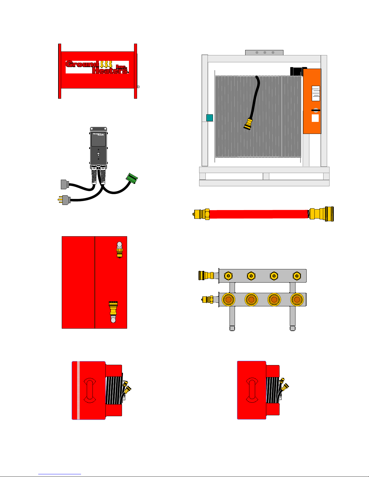
PUREHEAT AIR AND SURFACE HEATING ACCESSORIES
BOOSTER PUMP
(P/N G109-014)
AUXILIARY PUMP PANEL
Auxiliary
Pump
Panel
o
(P/N A109-199)
HHS 3004
(P/N G302-009)
Y
S
S
A
E
S
O
H
T
E
C
S
Q
.
W
/
HX200 Heat Xchanger™
(P/N G109-005)
HX100 Heat Xchanger™
1 IN. I.D. RED
50 FT LENGTH (P/N A109-136)
100 FT LENGTH (P/N A109-137)
200 FT LENGTH (P/N A109-138)
4 PORT REMOTE MANIFOLD
(P/N G109-009)
HX50 Heat Xchanger™
(P/N G109-007)
V. 2, Rev. 09/01/06
© 2006 Ground Heaters, Inc.
(P/N G109-006)
B - 1
Page 83
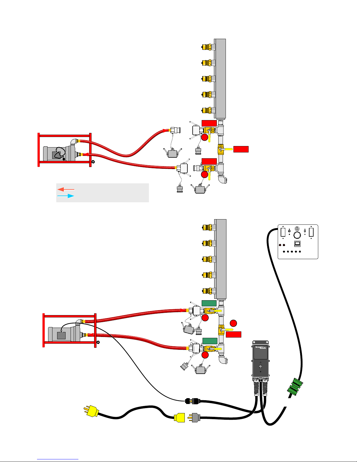
BOOSTER PUMP TO PUREHEAT CONNECTING
1.
ENSURE VALVES 5,6 AND 7 ARE SHUT.
REMOVE THE CAPS AND PLUGS FROM THE PUREHEAT
BOOSTER PUMP CONNECTION POINTS AND THE
BOOSTER PUMP HOSE ENDS.
SUPPLY MANIFOLD
SHUT
7
SHUT
SHUT
6
HTF SUPPLY - FLOW DIRECTION
HTF RETURN - FLOW DIRECTION
2.
JOIN BOOSTER PUMP AND PUREHEAT CAM-LOCKS
(REFER TO PAGE B-8)
OPEN VALVES 6 & 7 (VALVE 5 REMAINS SHUT)
CHECK FOR HTF LEAKS.
3.
CONNECT POWER SUPPLY TO AUX PUMP PANEL.
CONNECT BOOSTER PUMP TO AUX PUMP PANEL.
JOIN AUX PUMP CABLES.
SUPPLY MANIFOLD
OPEN
7
SHUT
OPEN
6
MAIN CONTROL PANEL
5
Auxiliary
Pump
Panel
B - 2
O
U
T
2
0
A
© 2006 Ground Heaters, Inc.
o
t
o
P
um
p
P
o
w
e
r
I
N
Aux. Pump Cable
V. 2, Rev. 09/01/06
Page 84
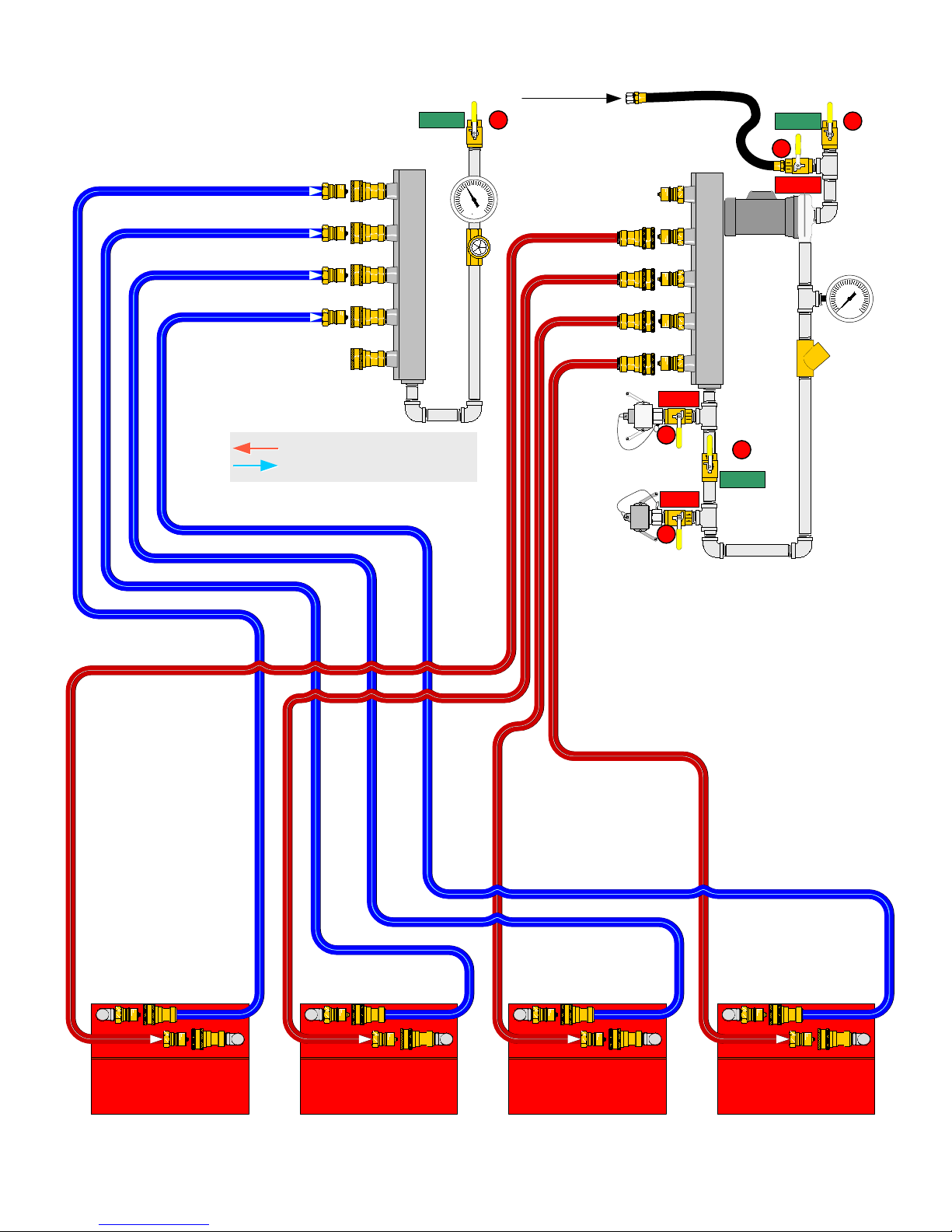
HX200 HEAT XCHANGER™ TO PUREHEAT CONNECTION LAYOUT
FILL HOSE DUST CAP
OPEN
2
FILL HOSE
OPEN
3
RETURN MANIFOLD
HTF SUPPLY - FLOW DIRECTION
HTF RETURN - FLOW DIRECTION
4
SUPPLY MANIFOLD
F
SHUT
SHUT
MAIN
PUMP
PRESSURE
GAUGE
PSI
CHECK
VALVE
7
5
OPEN
SHUT
6
HX200
(P/N G109-005)
V. 2, Rev. 09/01/06
HX200
(P/N G109-005)
© 2006 Ground Heaters, Inc.
HX200
(P/N G109-005)
HX200
(P/N G109-005)
B - 3
Page 85
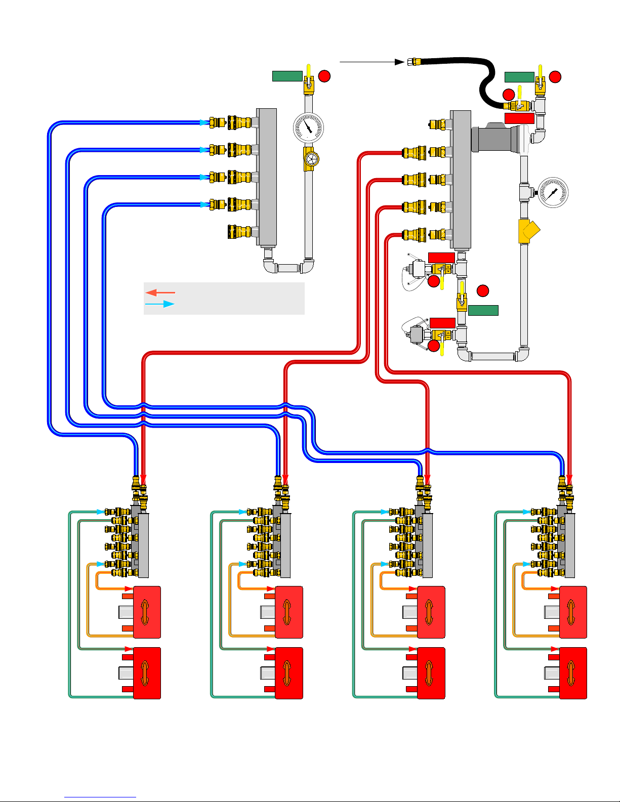
HX100 HEAT XCHANGER™ TO PUREHEAT CONNECTION LAYOUT
FILL HOSE DUST CAP
OPEN
2
FILL HOSE
OPEN
3
RETURN MANIFOLD
HTF SUPPLY - FLOW DIRECTION
HTF RETURN - FLOW DIRECTION
4
SUPPLY MANIFOLD
F
SHUT
SHUT
MAIN
PUMP
PRESSURE
GAUGE
PSI
CHECK
VALVE
7
5
OPEN
SHUT
6
FOUR PORT
MANIFOLD 1
B - 4
FOUR PORT
MANIFOLD 2
FOUR PORT
MANIFOLD 3
© 2006 Ground Heaters, Inc.
FOUR PORT
MANIFOLD 4
V. 2, Rev. 09/01/06
Page 86
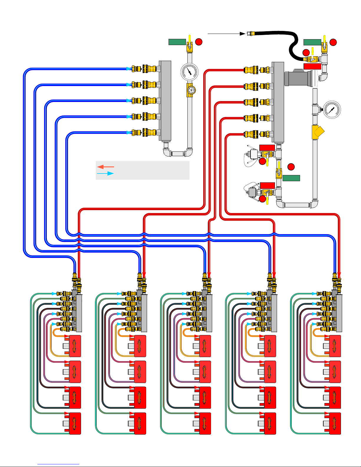
HX50 HEAT XCHANGER TO PUREHEAT CONNECTION LAYOUT
FILL HOSE DUST CAP
OPEN
2
FILL HOSE
OPEN
3
RETURN MANIFOLD
HTF SUPPLY - FLOW DIRECTION
HTF RETURN - FLOW DIRECTION
4
SUPPLY MANIFOLD
F
SHUT
SHUT
MAIN
PUMP
PRESSURE
GAUGE
PSI
CHECK
VALVE
7
5
OPEN
SHUT
6
FOUR PORT
MANIFOLD 1
V. 2, Rev. 09/01/06
FOUR PORT
MANIFOLD 2
FOUR PORT
MANIFOLD 3
© 2006 Ground Heaters, Inc.
FOUR PORT
MANIFOLD 4
FOUR PORT
MANIFOLD 5
B - 5
Page 87
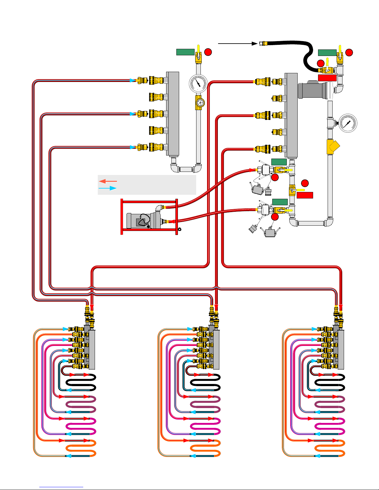
PUREHEAT 18,000 SQ. FT THAW LAYOUT
(THREE HHS 3004'S AND THREE 4-PORT MANIFOLDS)
FILL HOSE DUST CAP
OPEN
2
FILL HOSE
OPEN
3
RETURN MANIFOLD
HTF SUPPLY - FLOW DIRECTION
HTF RETURN - FLOW DIRECTION
4
SUPPLY MANIFOLD
F
OPEN
SHUT
MAIN
PUMP
PRESSURE
GAUGE
PSI
CHECK
VALVE
7
5
SHUT
OPEN
6
B - 6
© 2006 Ground Heaters, Inc.
V. 2, Rev. 09/01/06
Page 88
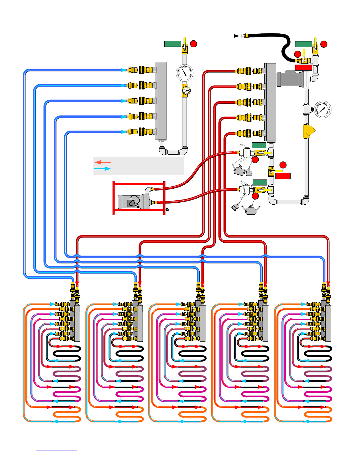
PUREHEAT 30,000 SQ. FT CURE LAYOUT
(FIVE HHS 3004'S AND FIVE 4-PORT MANIFOLDS)
OPEN
FILL HOSE DUST CAP
2
FILL HOSE
OPEN
3
RETURN MANIFOLD
HTF SUPPLY - FLOW DIRECTION
HTF RETURN - FLOW DIRECTION
4
SUPPLY MANIFOLD
F
OPEN
SHUT
MAIN
PUMP
PRESSURE
GAUGE
PSI
CHECK
VALVE
7
5
SHUT
OPEN
6
V. 2, Rev. 09/01/06
© 2006 Ground Heaters, Inc.
B - 7
Page 89
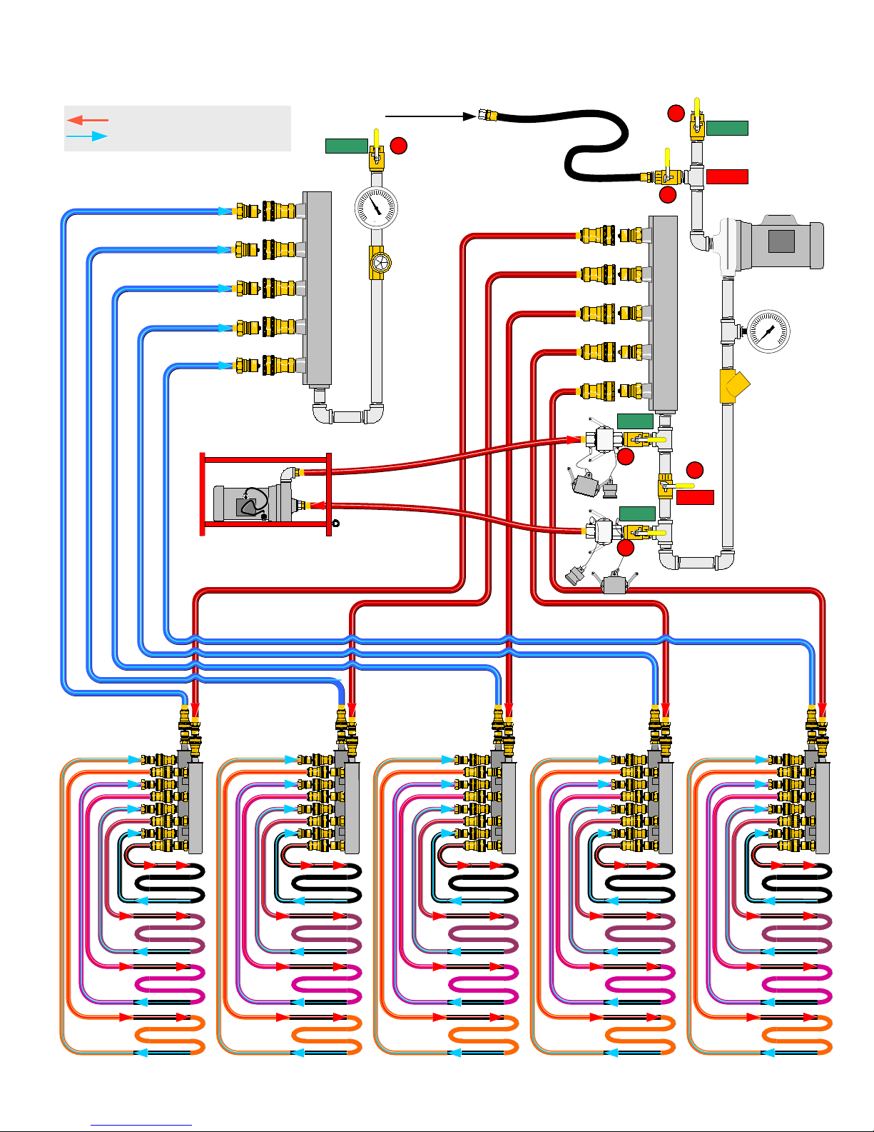
PUREHEAT 45,000 SQ. FT FROST PREVENTION LAYOUT
(FIVE HHS 3004'S AND FIVE 4-PORT MANIFOLDS)
HTF SUPPLY - FLOW DIRECTION
HTF RETURN - FLOW DIRECTION
RETURN MANIFOLD
FILL HOSE DUST CAP
OPEN
F
2
RETURN HTF
THERMOMETER
FILL HOSE
SUPPLY MANIFOLD
OPEN
7
OPEN
4
3
5
SHUT
OPEN
SHUT
SUCTION VALVE
HTF FILL
VALVE
MAIN
PUMP
PRESSURE
GAUGE
PSI
CHECK
VALVE
6
B - 8
© 2006 Ground Heaters, Inc.
V. 2, Rev. 09/01/06
Page 90
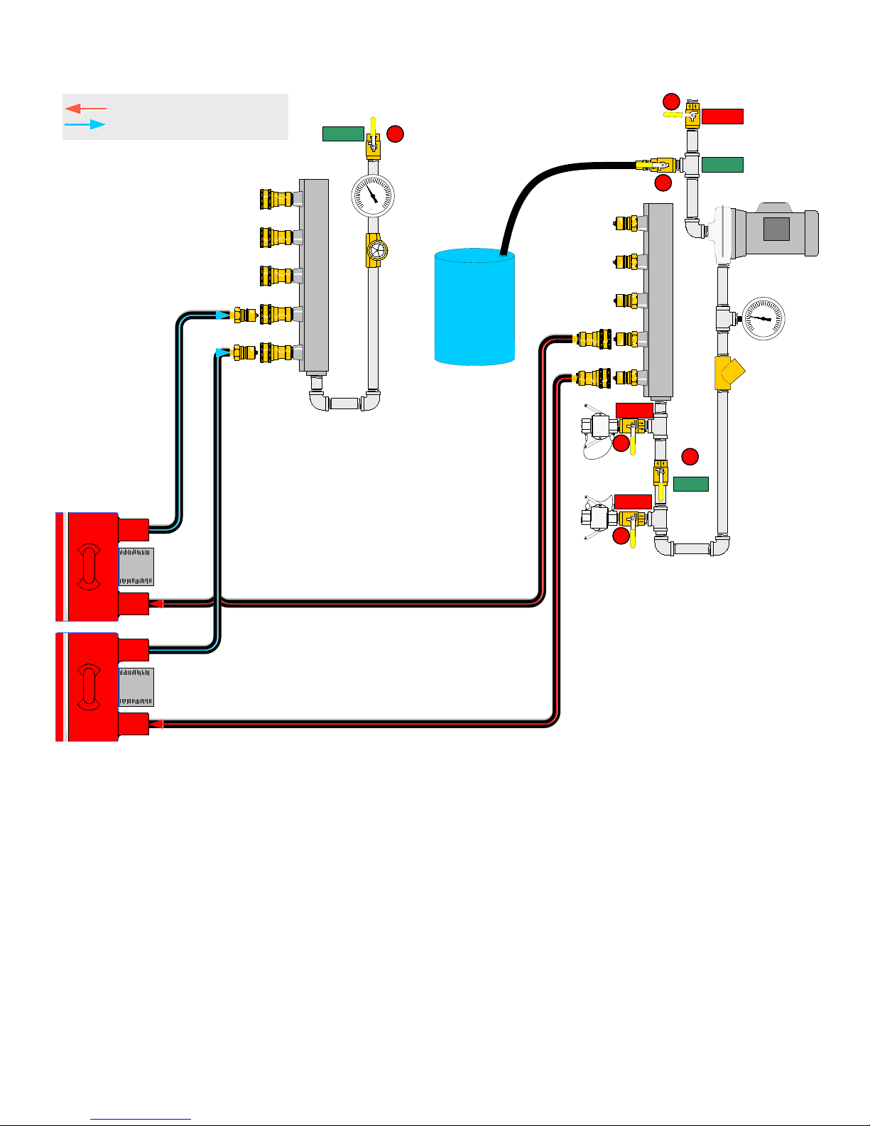
PUREHEAT VALVE POSITIONS FOR ADDING HTF
(Machine in use)
HTF SUPPLY - FLOW DIRECTION
HTF RETURN - FLOW DIRECTION
RETURN MANIFOLD
OPEN
2
RETURN HTF
THERMOMETER
F
HTF
FILL HOSE
SUPPLY MANIFOLD
SHUT
7
SHUT
4
3
OPEN
SHUT
SUCTION VALVE
OPEN
HTF FILL
VALVE
MAIN
PUMP
PRESSURE
GAUGE
PSI
CHECK
VALVE
5
6
1. Power up the PureHeat as described in section 2 of this manual.
2. Place the container of HTF near the access doors for the Hose Reel and the Main Control Panel.
3. Remove the Fill Hose from its storage location below the hose reel.
4. Clean the exterior of the Fill Hose and place the open end in the container of HTF.
5. It may be necessary to fill (prime) the Fill Hose prior to insertion into the HTF container.
This is accomplished by first lowering the hose near ground elevation and momentarily opening Valve #4 until HTF has filled the hose.
6. SHUT Pump Suction Valve #3
7. Pull the locking pin from Valve #4, pull the locking collar toward the handle and OPEN valve #4
8. If the LOW HTF LEVEL light is lit, push and hold the HTF FILL switch to operate the Pump.
If the LOW HTF LEVEL light is NOT lit, you may turn the pump switch ON to begin filling.
9. Continue filling until the HTF is observed in-between the LOW and HIGH marks adjacent to the HTF Sight Gauge. (photo 2-4, page 2.4)
10. Once filling is complete, pull the Fill Hose out of the HTF container with the Main Pump running to effect emptying the Fill Hose.
11. Shut Valve #4, ensure the locking collar slides toward the valve stem to the locked position, place the locking pin into the hole provided.
12. Turn the Pump Switch OFF.
13. Wipe down the fill hose and store it neatly below the Hose Reel.
14. Open Pump Suction Valve #3, check for leaks.
V. 2, Rev. 09/01/06
© 2006 Ground Heaters, Inc.
B - 9
Page 91
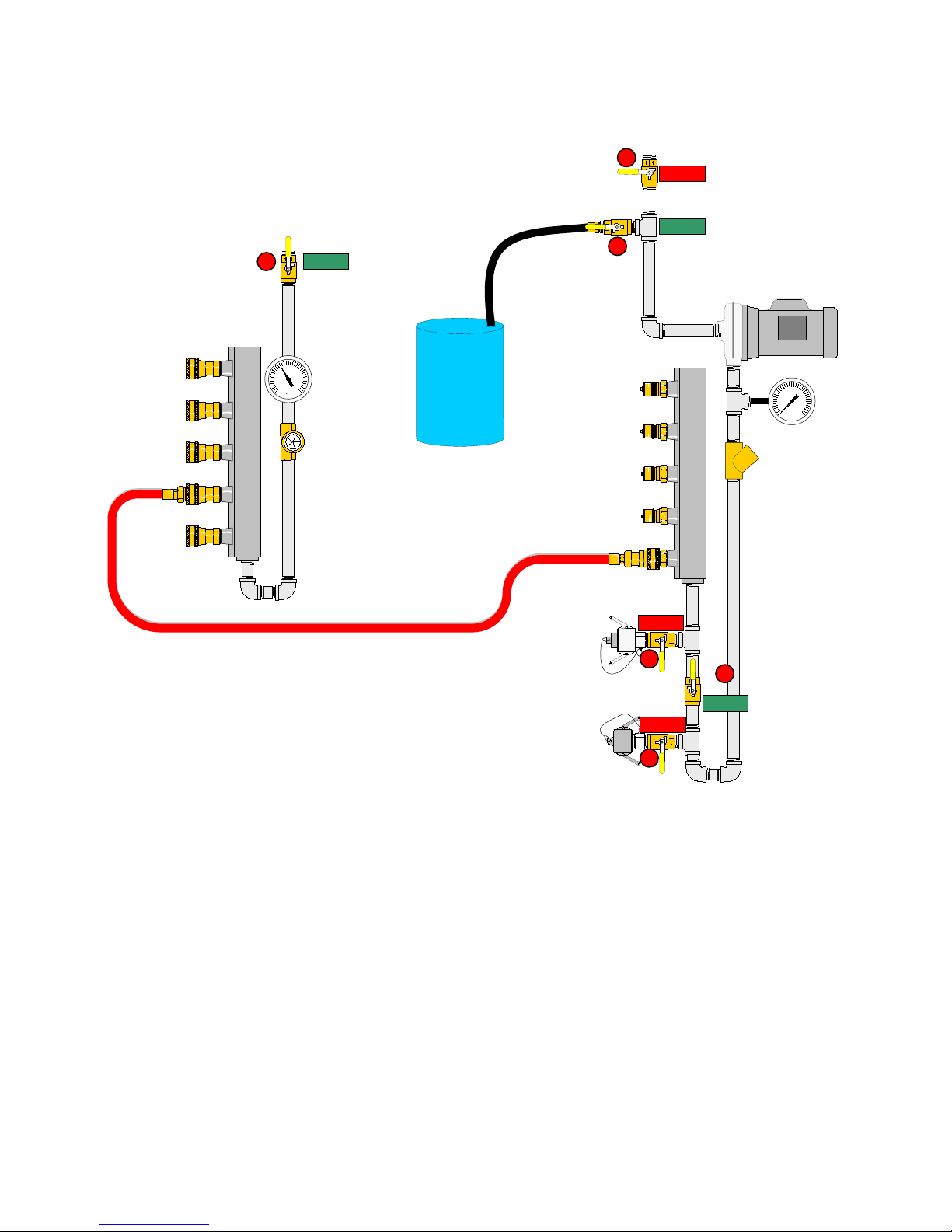
PUREHEAT VALVE POSITIONS FOR ADDING HTF
(Machine not in use)
3
SHUT
SUCTION VALVE
RETURN MANIFOLD
OPEN
HTF FILL
VALVE
4
OPEN
2
F
FILL HOSE
HTF
SUPPLY MANIFOLD
SHUT
CHECK
VALVE
PSI
MAIN
PUMP
PRESSURE
GAUGE
7
5
OPEN
SHUT
6
1. Power up the PureHeat as described in section 2 of this manual.
2. Attach a hose equipped with Quick-Connect fittings to the Supply and Return Manifold in order to provide a complete fluid path prior to adding HTF.
3. Place the container of HTF near the access doors for the Hose Reel and the Main Control Panel.
4. Remove the Fill Hose from its storage location below the hose reel and clean the exterior.
5. Prime the Fill Hose prior to insertion into the HTF container by lowering the hose near ground elevation, pull the locking pin out of Valve #4,
slide the locking collar toward the handle, open the valve partially until HTF is observed filling the hose.
6. SHUT Pump Suction Valve #3
7. Attach a hose equipped with Quick-Connect fittings to the Supply and Return Manifold in order to provide a complete fluid path prior to adding HTF.
8. Pull the locking pin from Valve #4, pull the locking collar toward the handle, (unless it was done at step 5) OPEN valve #4.
9. If the LOW HTF LEVEL light IS ON, push and hold the HTF FILL switch to operate the Pump.
10. If the LOW HTF LEVEL light is NOT ON, you may turn the pump switch ON to begin filling.
11. Continue filling until the HTF is observed in-between the LOW and HIGH marks adjacent to the HTF Sight Gauge. (photo 2-4, page 2.4)
12. Once filling is complete, pull the Fill Hose out of the HTF container with the Main Pump running to effect emptying the Fill Hose.
13. Shut Valve #4, ensure the locking collar slides toward the valve stem to the locked position, place the locking pin into the hole provided.
14. Turn the Pump Switch OFF.
15. Wipe down the fill hose and store it neatly below the Hose Reel.
16. Open Pump Suction Valve #3, check for leaks.
B - 10
© 2006 Ground Heaters, Inc.
V. 2, Rev. 09/01/06
Page 92
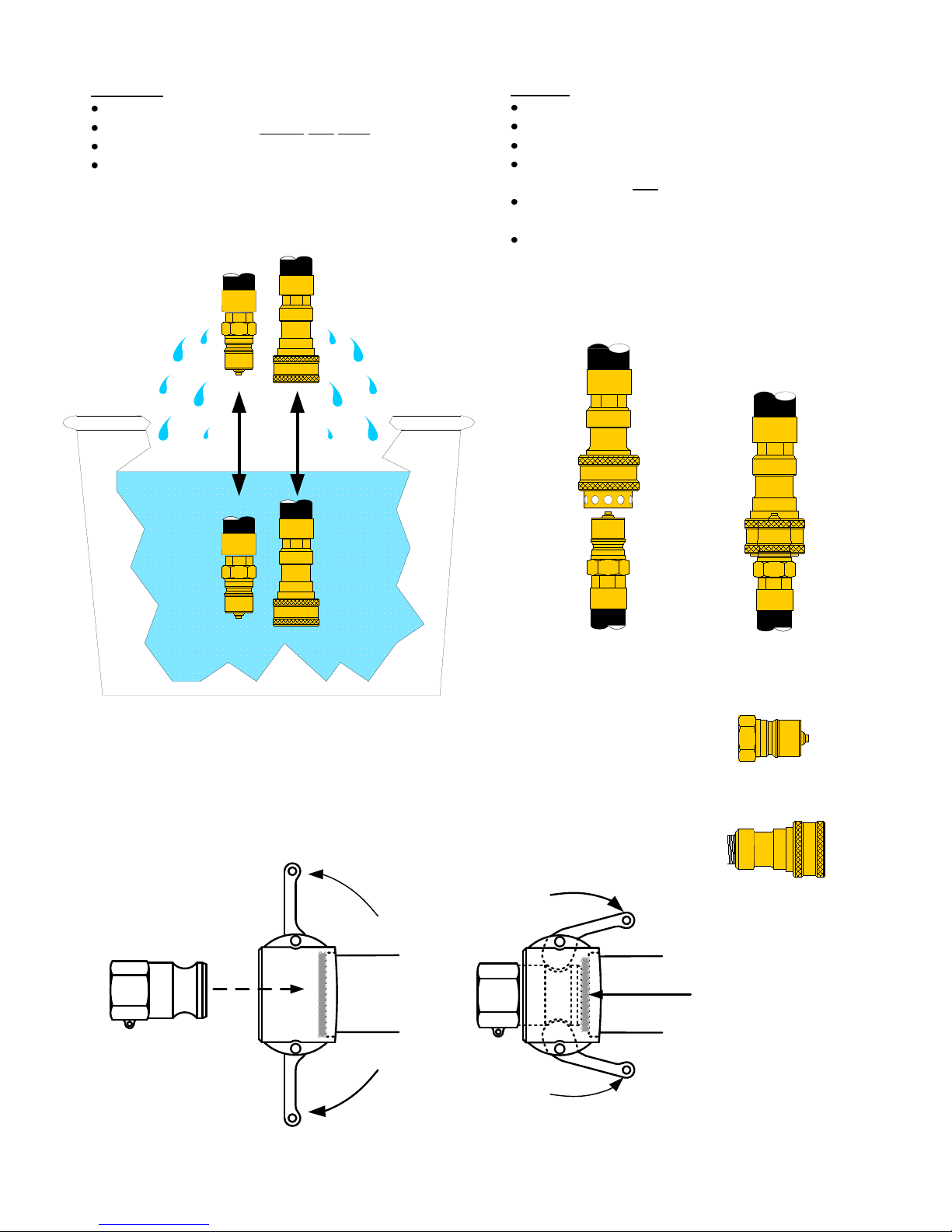
PUREHEAT QUICK-CONNECT AND CAM-LOCK CARE AND MAINTENANCE
ALWAYS:
Keep connection devices free of sand and dirt.
Rinse in clear water before and after each use.
Inspect seals and gaskets before and after each use.
Reinstall caps or protective covers after each use.
1
RINSE
NEVER:
Drop onto a hard surface such as concrete.
Drive over with any size vehicle.
Attempt to use damaged connection devices.
Attempt to use when contaminated with soil,
vegetation or any
petroleum product.
Attempt to use with damaged or worn seals or
gaskets.
Lubricate with petroleum products.
2
PUSH LOCKING
RING BACK
QUICK-CONNECT,
3
INSERT MALE
RELEASE LOCKING RING
MALE CAM-LOCK
P/N M100-700
MALE QUICK CONNECT
(P/N M100-258)
Unlock the Cam-Lock by swinging the locking arms
outward. Insert the male fitting and lock by simultaneously
swinging the arms inward as shown.
FEMALE CAM-LOCK
P/N M100-728
MALE QUICK CONNECT
(P/N M100-258)
FEMALE QUICK CONNECT
(P/N M100-259)
VITON GASKET
P/N P100-352
V. 2, Rev. 09/01/06
© 2006 Ground Heaters, Inc.
B - 11
Page 93
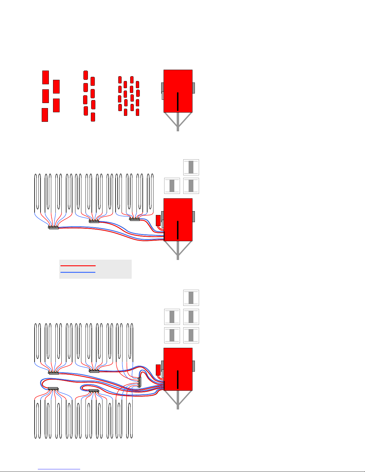
PUREHEAT APPLICATIONS AND CAPACITIES
(See Appendix pages B-1 – B-10 for accessories connecting)
HX200 HX100
HX50
PUREHEAT, FIVE HX200 or, EIGHT HX100 or,
TWENTY HX50 HEAT XCHANGERS™
THAWING
N/A
CURING
N/A
FROST PREVENTION
N/A
AIR HEATING
3
Up to: 1,200.00 ft
(with Propane Fuel @ .6 BTU per ft3)
PUREHEAT, ONE Booster Pump, 3 HHS3004,
THREE Four Port Manifolds
( TWELVE 750 FT HOSE LOOPS)
THAWING
2
Up to: 18,000 ft
@ 24 in hose spacing
HTF SUPPLY
HTF RETURN
CURING
2
Up to: 18,000 ft
@ 24 in hose spacing
FROST PREVENTION
2
Up to: 18,000 ft
@ 36 in hose spacing
PUREHEAT, ONE Booster Pump, FIVE HHS3004,
FIVE Four Port Manifolds
(TWENTY 750 FT HOSE LOOPS)
THAWING
2
Up to: 30,000 ft
@24 in hose spacing
CURING
2
Up to:30,000 ft
@ 24 in hose spacing
FROST PREVENTION
2
Up to: 45,000 ft
@ 36 in hose spacing
C - 1
© 2006 Ground Heaters, Inc.
V. 2, Rev. 09/01/06
Page 94

Page 95

Page 96

Wacker Construction Equipment AG · Preußenstraße 41 · D-80809 München · Tel.: +49-(0)89-3 54 02 - 0 · Fax: +49 - (0)89-3 54 02-3 90
Neuson Corporation · P.O. Box 9007 · Menomonee Falls, WI 53052-9007 · Tel. : (262) 255-0500 · Fax: (262) 255-0550 · Tel. : (800) 770-0957
Wacker
Wacker Asia Pacific Operations · Skyline Tower, Suite 2303, 23/F · 39 Wang Kwong Road, Kowloon Bay, Hong Kong · Tel. +852 2406 60 32 · Fax: +852 2406 60 21
 Loading...