

Page 1
Installation, Operation and Maintenance Manual for
Back Pressure Regulator
Model 8860
IOM-8860
Rev. B 12541
©2009 Groth Corporation
Ref. ID: 95565
Page 2

IOM -8860
Page 2 of 13
Table of Contents
I. INTRODUCTION 3
II. DESIGN AND FUNCTION 4
III. SAFETY WARNINGS 5
IV. INSPECTION AND STORAGE 5
V. INSTALLATION 6
a. 6
b. 6
VI. MAINTENANCE 7
a. FIGURE 4 – 7
b. TABLE 3 – 8
VII. VALVE TESTING PROCEDURE 8
VIII. MODEL IDENTIFICATION 9
APPENDIX A – MODEL 1200A PRESSURE/VACUUM RELIEF VALVE 10
APPENDIX B – MODEL 1220A PRESSURE/VACUUM RELIEF VALVE 11
APPENDIX C – MODEL 1260A PRESSURE RELIEF VALVE 12
APPENDIX D – MODEL 1300A VACUUM RELIEF VALVE 13
APPENDIX E – MODEL 1360A VACUUM RELIEF VALVE 14
APPENDIX F – MODEL 2300A PRESSURE RELIEF VALVE 15
13650 N. Promenade Blvd. * Stafford, TX 77477
Office: (281) – 295-6800 * (800) – 354-7684 * Fax: (281) – 295-6999 * www.grothcorp.com
Page 3

IOM -8860
Page 3 of 13
I. INTRODUCTION
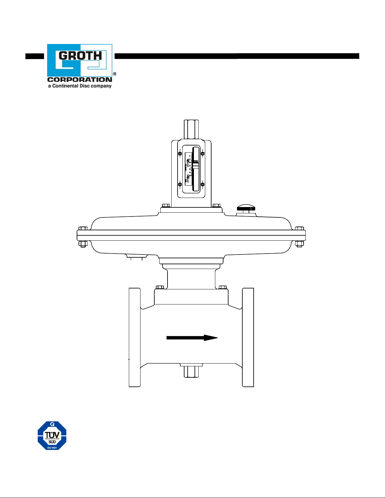
The Groth Model 8860 Back Pressure Regulator controls upstrea m pressure in a process line such as
an anaerobic digester gas control system. The pressure setting is obtained by adjustable spring
compression and opening is caused by upstream pressure acting on a large diaphragm. A visible scale
indicates approximate set pressure. Springs are available for various standard and special set
pressure ranges.
The regulator must be maintained by a knowledgeable valve technician. It should only be assembled
under clean conditions, preferably in a shop environment. Carefully read and understand this manual
before attempting to adjust set pressure or flow capacity, or repair the regulator.
For information not contained in this manual, please contact:
Groth Corporation
13650 N. Promenade Blvd.
Stafford, TX, 77477 USA
Phone: 281-295-6800
Fax: 281-295-6999
www.grothcorp.com
13650 N. Promenade Blvd. * Stafford, TX 77477
Office: (281) – 295-6800 * (800) – 354-7684 * Fax: (281) – 295-6999 * www.grothcorp.com
Page 4

IOM -8860
Page 4 of 13
II. DESIGN AND FUNCTION
The Groth Model 8860 Back Pressure regulator is a high capacity, low pressure in-line pressure relief
valve. It controls upstream pressure by discharging excess vapor downstream.
When the diaphragm force, due to upstream pressure, equals the spring compression, the regulator
begins to open. Opening is controlled to accommodate the required vapor flow. Full capacity is
achieved at 15-25% over-pressure [above set pressure]. When system pressure returns to set
pressure or below, the regulator closes.
Upstream vapor pressure, acting on a large diaphragm, forces the regul ator open at the specified set
pressure. For best performance, set pressure should be sensed at a remote location at least ten pipe
diameters upstream from the regulator. The upstream pressure acts on the lower surface of the
diaphragm. The upper side of the diaphragm must be vented to atmosphere.
Set pressure is determined by the compression of the spring; the greater the compression of the
spring, the higher line pressure required to overcome the spring force. The scale located on the
regulator is a close approximation of the set pressure. A manometer is recommended for a high
accuracy reading of the set pressure. The manometer should be plumbed upstream of the Back
Pressure Regulator, at lease ten pipe diameters.
The seat and disc are lapped flat surfaces with metal to metal contact.
III. SAFETY WARNINGS
This section is intended as an overview of safety guidelines that should be followed during the
installation, operation and maintenance of the Groth Model 8860 Back Pressure Regulator. To
understand the context of these warnings and instructions, read and understand this complete manual.
In the event of an actuator diaphragm failure, the regulator will fail in the CLOSED position.
Vapor flow will be shut off. WITHOUT PROPER PIPELINE PRESSURE SENSING, EXCESSIVE
PRESSURE CAN BE REACHED.
Regulator flow capacity is based on a fully open regulator flowing air or a vapor with SG=0.7.
Consult factory for capacity under other conditions.
DO NOT attempt to re-adjust the set pressure beyond the limits specified in Table 3.
The regulator is to be connected to the upstream line with a minimum .31" ID tubing sense line.
This line must be kept open and unobstructed to ensure that the regulator senses the actual
line pressure. Long sense lines may require a larger diameter and care must be taken DURING
INSTALLATION to assure that the line is self-draining.
DO NOT attempt to remove the regulator from the line or perform field repairs in line without
first isolating the regulator from both upstream and downstream systems.
The regulator body and actuator housing are exposed to process vapors. Observe all safety
precautions as specified on the Material Safety Data Sheet(s) for the prod uct(s) that are in the
system.
The vent on the upper actuator housing must be clean and open to the atmosphere and SHALL
be inspected periodically.
The recommended set pressure range of the regulator spring is stamped on the namep l ate.
Never adjust a spring for a set pressure beyond its design range as specified in Table 3.
13650 N. Promenade Blvd. * Stafford, TX 77477
Office: (281) – 295-6800 * (800) – 354-7684 * Fax: (281) – 295-6999 * www.grothcorp.com
Page 5
IOM -8860
Page 5 of 13
Exceeding the spring upper limit may compress the spring to its solid height, and prevent the
regulator from opening. Setting it below the lower limit may prevent the regulator from closing
fully at the required pressure.
PROCESS PIPING IS TO BE CLEAN AND FREE OF WELD SLAG. WELD SLAG OR OTHER
DEBRIS COULD BLOCK THE SENSE LINE OR DAMAGE THE REGULATOR SEATING SURFACE.
DO NOT LIFT THE BACK PRESSURE REGULATOR FROM THE ADJUSTMENT SCREW. IF
LIFTED FROM THIS LOCATION, THE ADJUSTMENT SCREW MAY BE PERMANENTLY
DAMAGED.
USING AN IMPROPER PRESSURE SENSING LINE CAN RESULT IN LIMITED OR NO
FUNCTIONALITY OF THE REGULATOR. RECOMMENDED SIZE FOR THE PRESSURE SENSING
LINE IS AT LEAST .31”. THIS LINE MUST REMAIN FREE OF DEBRIS AND ANY TYPE OF
OBSTRUCTION.
IV. INSPECTION AND INSTALLATION
The regulator is packaged and supported to prevent damage or contamination during shipment. The
regulator shall also be protected during subsequent handling and storage. Always keep all ports
plugged to prevent intrusion of foreign materials. Before installation, inspect the unit visually. If there
are indications of physical damage or internal contamination, the regulator must be disassembled,
cleaned and inspected before installation. If factory set, the spring adjustment cap must be secure.
Report any shipping damage to carrier.
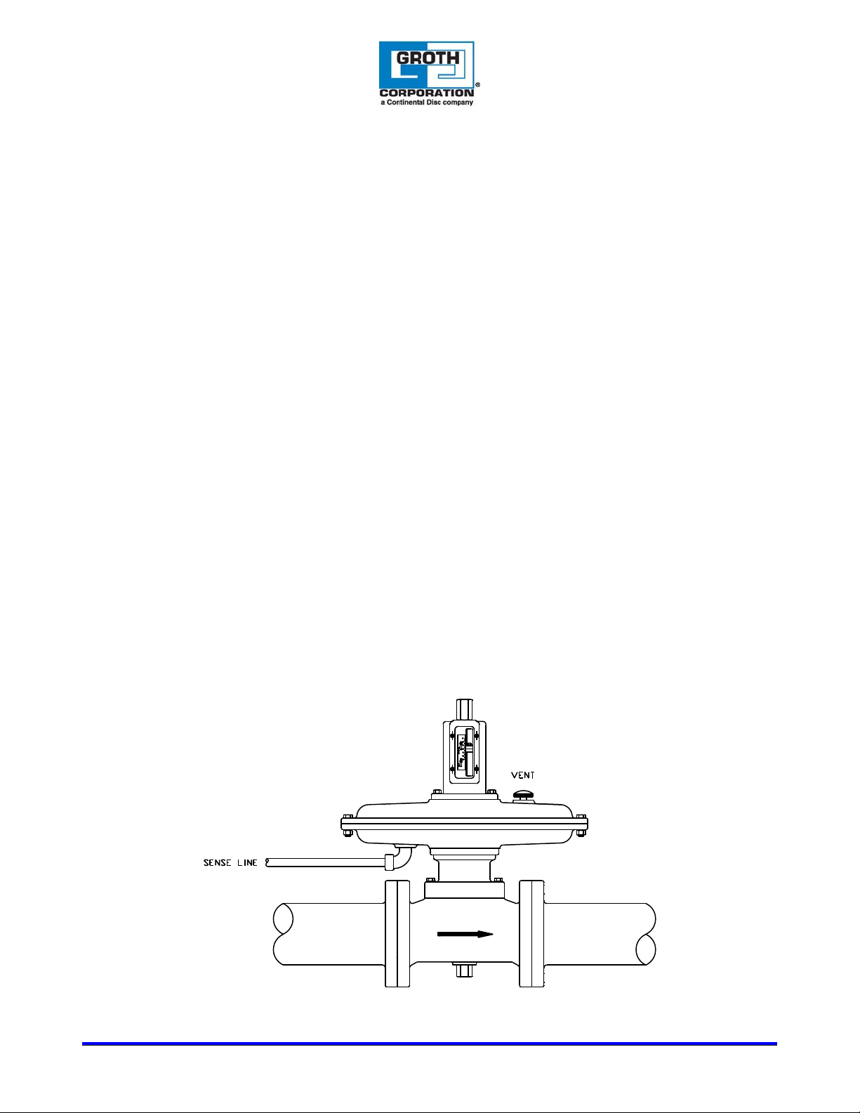
The regulator must be installed in a horizontal line as shown in Figure 1. Use the actuator housing or
valve body to lift and support the regulator at installation.
1. Aluminum bodies should be connected with flat-faced 150# ANSI flanges using a full-faced gasket.
Mating flanges should be flat within .020", clean, free of scratches, corrosion and tool marks.
2. Steel bodies should be connected with raised-faced 150# ANSI flanges using a full-faced or ring
gasket. Mating flanges should be flat within .020", clean, free of scratches, corrosion and tool
marks.
3. Each valve is leak tested at the factory as part of our standard inspection procedures.
4. Inspect the gasket; make sure that the material is suitable for the service. Gasket dimensions are
listed in Table 1. Full gaskets must be used with flat face flanges. Either full or ring gaskets may be
used with raised face flanges.
Figure 1: Regulator
13650 N. Promenade Blvd. * Stafford, TX 77477
Office: (281) – 295-6800 * (800) – 354-7684 * Fax: (281) – 295-6999 * www.grothcorp.com
Page 6
IOM -8860
Page 6 of 13
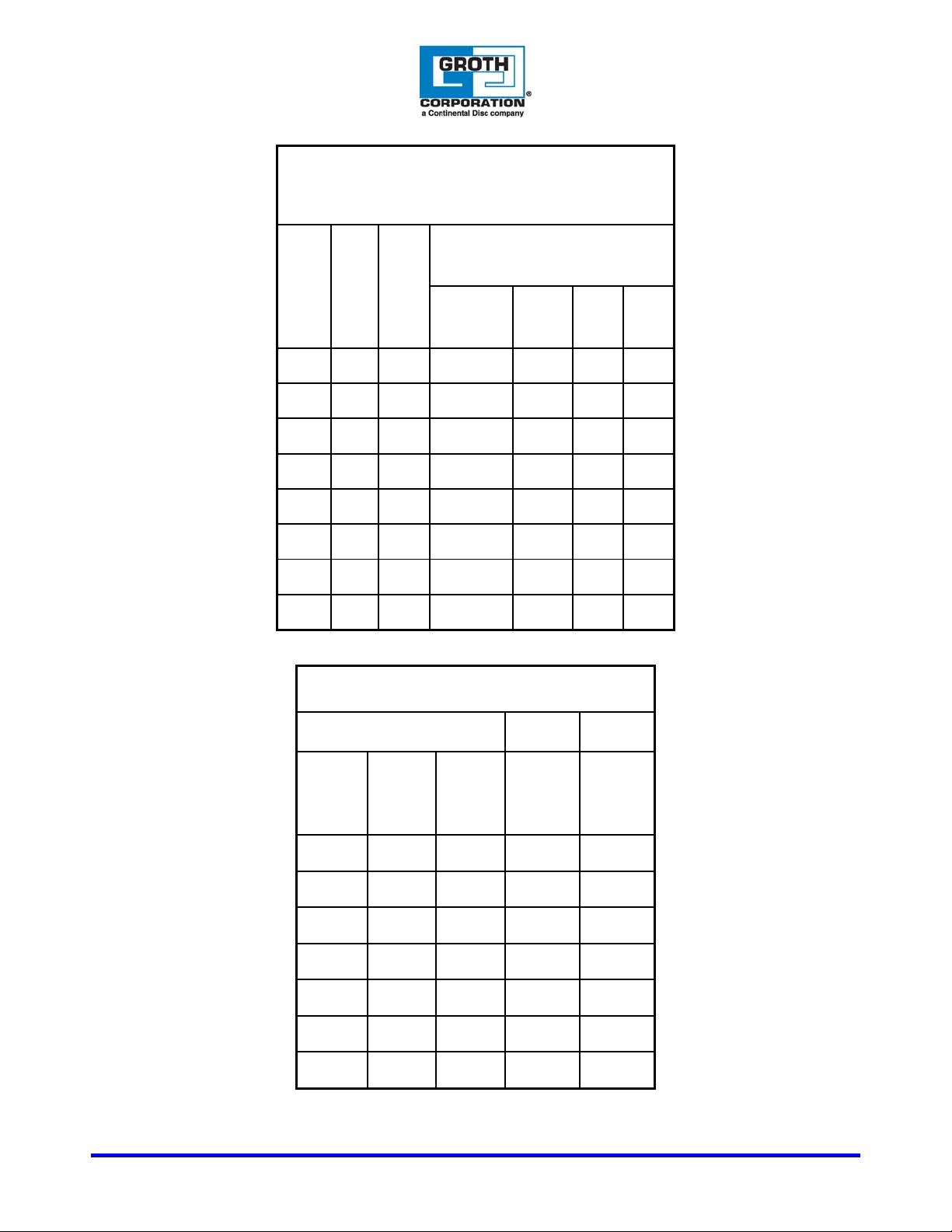
Table 1
Inlet/Outlet Flange Gasket Dimensions
Full Face Gasket
ANSI
150#
I.D.
Ring
O.D.
Outer
Diameter
Bolt
Circle
Hole
Size
Hole
Qty
2 2.38 4.12 6 4.75 0.75 4
3 3.5 5.38 7.5 6 0.75 4
4 4.5 6.88 9 7.5 0.75 8
6 6.62 8.75 11 9.5 0.88 8
8 8.62 11 13.5 11.75 0.88 8
10 10.8 13.4 16 14.25 1 12
12 12.8 16.1 19 17 1 12
16” 16 20.3 23.5 21.25 1.12 16
Flange
Size
(ANSI
150#)
Table 2: Bolt Torque
Flat Face & Raised Face Flange
Qty.
of
Bolts
Stud
Size
(UNC)
Flat
Face
Torque:
Foot-
Pound
(Kg*m)
Raised
Face
Torque:
Foot-
Pound
(Kg*m)
2” 4 5/8”-11 81 (11) 31 (4.3)
3” 4 5/8”-11 106 (15) 43 (6.0)
4” 8 5/8”-11 68 (9.4) 29 (4.0)
6” 8 3/4"-10 101 (14) 51 (7.1)
8” 8 3/4"-10 142 (20) 78 (11)
10” 12 7/8”-9 138 (19) 75 (10)
12” 12 7/8”-9 179 (25) 93 (13)
13650 N. Promenade Blvd. * Stafford, TX 77477
Office: (281) – 295-6800 * (800) – 354-7684 * Fax: (281) – 295-6999 * www.grothcorp.com
Page 7

5. Lubricate all studs and nuts with an appropriate thread lubricant. If stainless steel fasteners are
used, use an anti-seize lubricant such as moly-disulfide.
6. Align flanges and gaskets. Make sure the flow path is not restricted by valve or gasket
misalignment.
7. Install nuts and lock washers and torque all fasteners to half the value listed in Table 2 below in a
staggered, alternating pattern.
8. Make sure that the flanges are not distorted and that the gasket is evenly compressed.
9. Make up the final torque and check that no further nut rotation occurs at the specified torque value.
Regulator flow capacity is based on a fully open regulator flowing air or a vapor with SG=0.7. Consult
factory for capacity under other conditions.
The regulator sense line is to be connected to the process line at a location at least ten feet upstream
with a minimum of .31" ID tubing. The sense port on the regulator is on the lower surface of the
actuator housing (see Figure 1). This line must be kept open and unobstructed to ensure that the
regulator "senses" the actual line pressure. Long sense lines may require a larger diam eter and care
must be taken to assure that the line is self-draining. For some applications, a nitrogen purge may be
required to ensure that this line remains open. Consult the factory for recommendations for remote
installations or vapors that may cause line obstructions.
All system piping must be free of weld slag and other debris before installing the regulator.
V. OPERATION
The regulator is set at the factory. The pressure setting can be changed while installed in the pro ce ss
piping system. The purpose of the regulator is to maintain set pressure at some point upstream in the
process, such as in the anaerobic digester tank. System pressure shall be monitored at this point.
Set pressure is set at the factory according to purchasing specifications. The range of set pressure for
standard springs are shown in Table 3. Other ranges are available with special spring s. The factory
setting and spring range are shown on the nameplate. The regulator will not function properly if the
setting is outside this range. If higher or lower settings are required, the necessary component s can be
obtained from Groth Corporation.
For in-line adjustment, a visible scale shows the approximate set pressure. From this setting, small
adjustments can be made while observing upstream system pressure. Remove the cap [1] and turn the
adjusting screw counter-clockwise to increase pressure or clockwise to decrease pressure. Replace
the cap when adjustment is complete.
IOM -8860
Page 7 of 13
13650 N. Promenade Blvd. * Stafford, TX 77477
Office: (281) – 295-6800 * (800) – 354-7684 * Fax: (281) – 295-6999 * www.grothcorp.com
Page 8
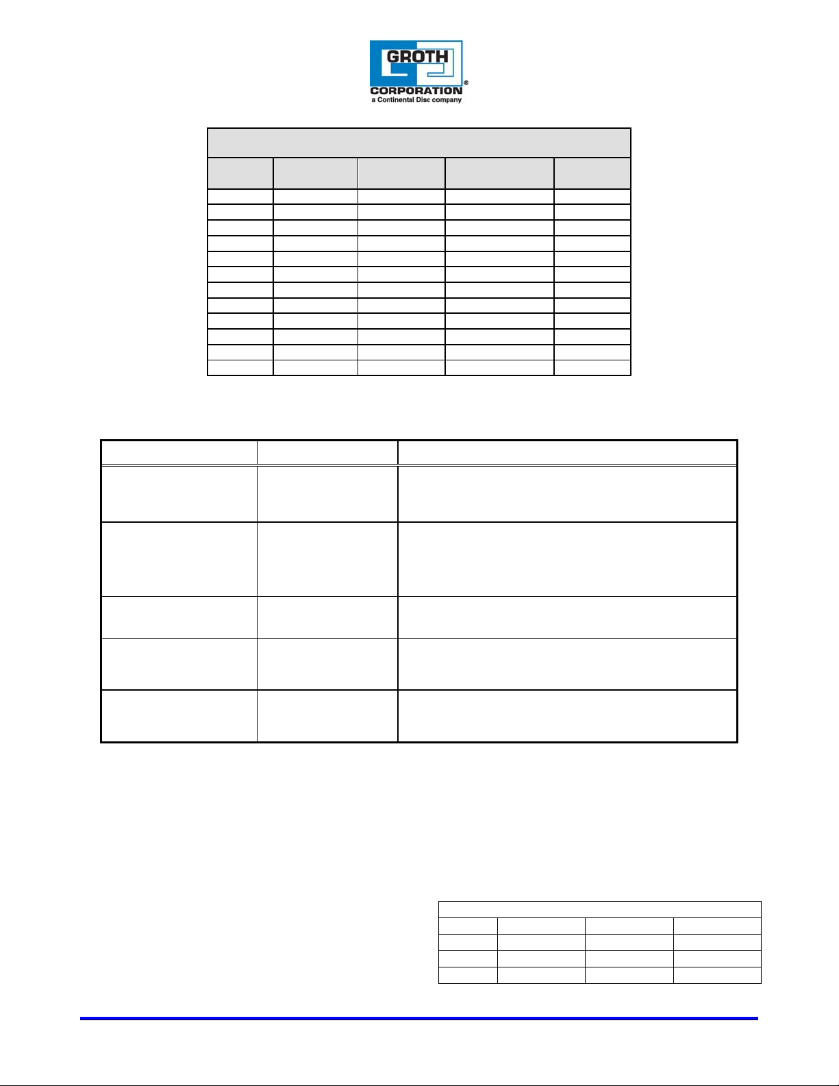
Flange
Size
2” 2” WC 12” WC SPR8860020120 313000101
2” 8” WC 24” WC SPR8860020220 313000201
3” & 4” 2” WC 12” WC SPR8860030120 313000101
3” & 4” 8” WC 24” WC SPR8860030220 313000201
6” & 8” 2” WC 12” WC SPR8860060120 313000101
6” & 8” 8” WC 24” WC SPR8860060220 313000201
10” & 12” 2" WC 6” WC SPR8860100320 313000301
10” 5” WC 12” WC SPR8860100520 313000401
10” & 12” 10” WC 22” WC SPR8860100420 313000501
10” & 12” 20" WC 44” WC SPR8860100620 313000601
12" 3” WC 8” WC SPR8860100520 313000701
12" 5” WC 12” WC SPR8860120520 313000401
VI. TROUBLESHOOTING GUIDE
PROBLEM INSPECTION SUGGESTED CORRECTIVE ACTION
IOM -8860
Page 8 of 13
TABLE 3
SPRING TABLE: MODEL 8860
Min. Setting Max. Setting Spring P/N Scale P/N
Vapor flowing at line
pressure below specified
set point.
Vapor not flowing at line
pressure above specified
set point.
Gas leaking from upper
vent.
System pressure above
specified operating
range.
System pressure below
specified operating
range.
Flow indicator or vapor
discharge.
Flow indicator or vapor
discharge.
Emission indication
near the regulator.
Observe pressure
indicator during
operation.
Observe pressure
indicator during
operation.
VII. PREVENTATIVE MAINTANANCE
Periodically, while in service, examine the regulator for leakage at bolted connections, adjusting
screws, and vent. Test for process vapor emissions from vent caps.
Periodically, out of service, examine seat and pallet for a smooth surface to ensure proper seating and
sealing. Examine actuator diaphragm for cuts, or unusual wear.
VIII. RECOMMENDED SPARE PARTS
Spring; see Table 3 for correct part number
Vent part number 285320147 (1/4” NPT)
Soft Goods Kit; see Table 4 for correct part
numbers
Damaged seat/disc or setting too low.
If original pressure setting has not been disturbed, remove
regulator and repair.
Damaged diaphragm or pressure setting too high.
If original pressure setting has not been disturbed, remove
regulator and repair.
Inspect the bushings for debris or damage.
Damaged diaphragm.
Remove regulator and replace diaphragm.
Damaged diaphragm or pressure setting too high.
Vapor flow exceeds capacity of regulator.
Damaged seat/disc or setting too low.
Insufficient vapor production.
Table 4: Soft Goods Kits
Size Buna-N EPDM FKM
2”-4” KS886002B KS886002E KS886002V
6”-8” KS886002B KS886002E KS886002V
10”-12” KS886002B KS886002E KS886002V
13650 N. Promenade Blvd. * Stafford, TX 77477
Office: (281) – 295-6800 * (800) – 354-7684 * Fax: (281) – 295-6999 * www.grothcorp.com
Page 9
IOM -8860
Page 9 of 13
IV. MODEL INFORMATION
The nameplate on the Groth Model 8860 Back Pressure Regulator contains the model nu mber, serial
number, set pressure & set pressure range. The model number contains additional information about
material of construction, capacity and options. The following chart will assist in relating the model
number to the specifications of your regulator:
----- ------ -------------
Model Number Inlet/Outlet Soft
Body Goods
Material
13650 N. Promenade Blvd. * Stafford, TX 77477
Office: (281) – 295-6800 * (800) – 354-7684 * Fax: (281) – 295-6999 * www.grothcorp.com
Page 10
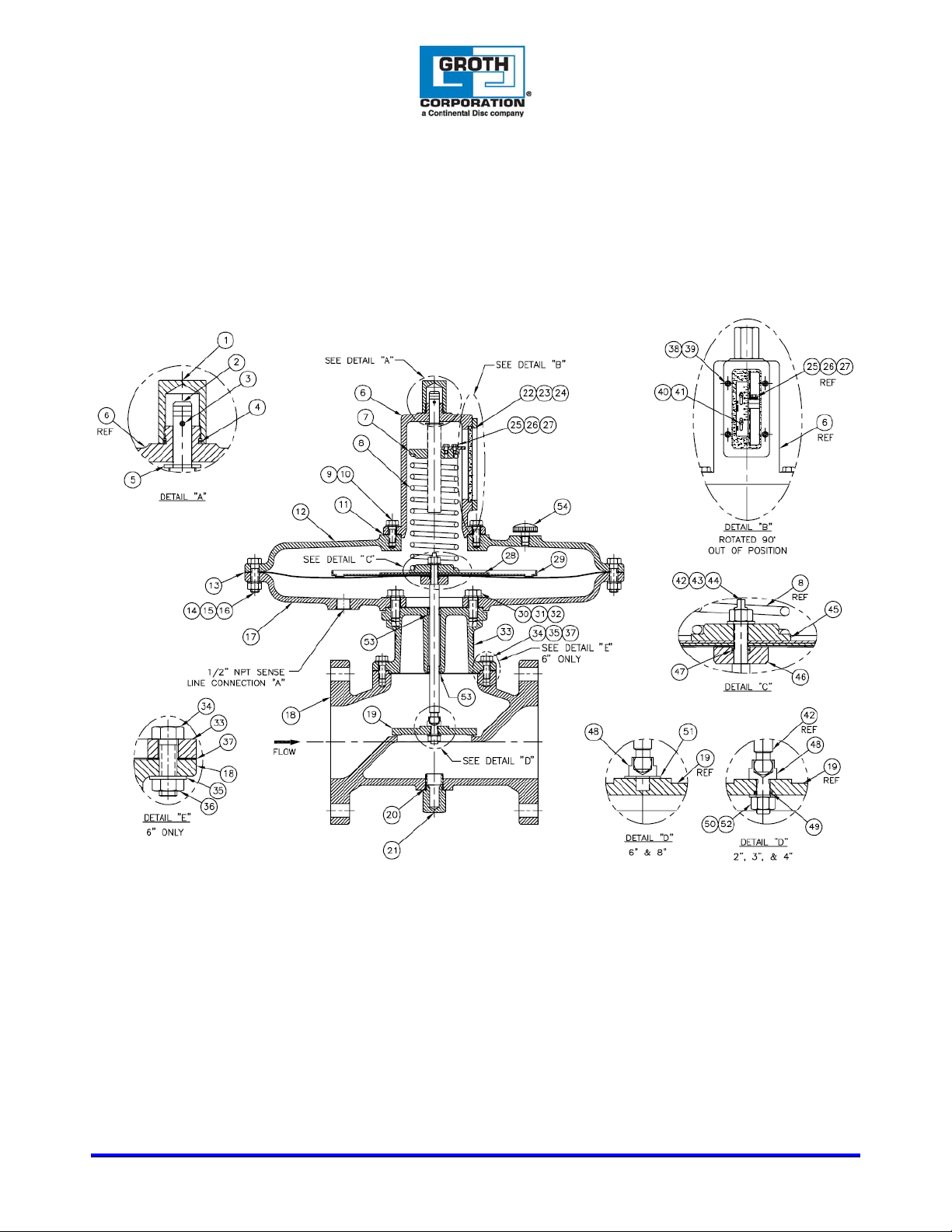
APPENDIX A – GROTH MODEL 8860 BACK PRESSURE REGULATOR (2”-8”)
IOM -8860
Page 10 of 13
Office: (281) – 295-6800 * (800) – 354-7684 * Fax: (281) – 295-6999 * www.grothcorp.com
13650 N. Promenade Blvd. * Stafford, TX 77477
Page 11

TABLE 5 – GROTH MODEL 8860 BACK PRESSURE REGULATOR (2”-8”)
BILL OF MATERIALS
ITEM DESCRIPTION ITEM DESCRIPTION
1 CAP-HOUSING 28 SUPPORT PLATE
2 ADJUSTMENT SCREW 29 RETAINER PLATE
3 ROLL PIN 30 HEX BOLT
4 * O-RING-UPPER HOUSING CAP 31 LOCK WASHER
5 WASHER 32 * GASKET-SPOOL LOWER CASE
6 SPRING HOUSING 33 SPOOL
7 SPRING BUTTON-UPPER 34 HEX BOLT
8 SPRING 35 LOCK WASHER
9 HEX BOLT 36 HEX NUT (6" ONLY)
10 LOCK WASHER 37 * GASKET-BODY
11 * GASKET-SPRING HOUSING 38 HEX BOLT
12 UPPER-DIAPHRAGM CASE 39 LOCK WASHER
13 * DIAPHRAGM 40 MACHINE SCREW
14 HEX BOLT 41 SCALE
15 LOCK WASHER 42 STEM
16 HEX NUT 43 HEX JAM NUT
17 LOWER-DIAPHRAGM CASE 44 BELLEVILLE WASHER
18 BODY 45 SPRING BUTTON-LOWER
19 PALLET 46 SPACER
20 * O-RING-LOWER CAP 47 * O-RING-SPACER
21 PLUG 48 SWIVEL FITTING
22 * GASKET-SIGHT GLASS 49 * O-RING-SWIVEL FITTING (2"-4" ONLY)
23 SIGHT GLASS 50 FLAT WASHER (2"-4" ONLY)
24 COVER-SIGHT GLASS 51 BELLEVILLE WASHER (6"-8" ONLY)
25 HEX BOLT 52 LOCK NUT (2"-4" ONLY)
26 LOCK WASHER 53 BUSHING
27 INDICATOR-PRESSURE 54 VENT
*spare parts
IOM -8860
Page 11 of 13
Office: (281) – 295-6800 * (800) – 354-7684 * Fax: (281) – 295-6999 * www.grothcorp.com
13650 N. Promenade Blvd. * Stafford, TX 77477
Page 12
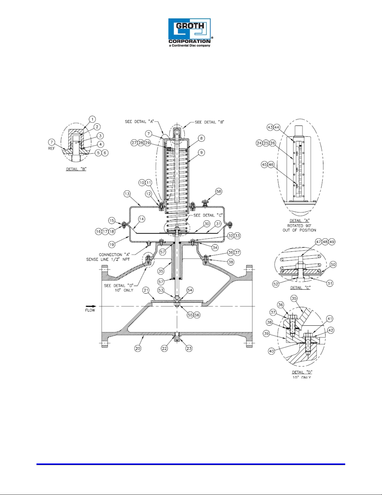
APPENDIX B – GROTH MODEL 8860 BACK PRESSURE REGULATOR (10”-12”)
IOM -8860
Page 12 of 13
Office: (281) – 295-6800 * (800) – 354-7684 * Fax: (281) – 295-6999 * www.grothcorp.com
13650 N. Promenade Blvd. * Stafford, TX 77477
Page 13

TABLE 5 – GROTH MODEL 8860 BACK PRESSURE REGULATOR (10”-12”)
ITEM DESCRIPTION ITEM DESCRIPTION
1 CAP-HOUSING 30 SUPPORT PLATE
2 ADJUSTMENT SCREW 31 RETAINER PLATE
3 ROLL PIN 32 HEX BOLT
4 * O-RING-UPPER HOUSING CAP 33 LOCK WASHER
5 WASHER 34 * GASKET-SPOOL LOWER CASE
6 WASHER 35 SPOOL
7 SPRING HOUSING 36 HEX BOLT
8 SPRING BUTTON-UPPER 37 LOCK WASHER
9 SPRING 38 * GASKET-BODY
10 HEX BOLT 39 ADAPTER PLATE (10" ONLY)
11 LOCK WASHER 40 * GASKET (10" ONLY)
12 * GASKET-SPRING HOUSING 41 HEX BOLT (10" ONLY)
13 UPPER-DIAPHRAGM CASE 42 LOCK WASHER (10" ONLY)
14 * DIAPHRAGM 43 HEX BOLT
15 * GASKET-DIAPHRAGM CASE 44 LOCK WASHER
16 HEX BOLT 45 MACHINE SCREW
17 LOCK WASHER 46 SCALE
18 HEX NUT 47 STEM
19 LOWER-DIAPHRAGM CASE 48 HEX JAM NUT
20 BODY 49 BELLEVILLE WASHER
21 PALLET 50 SPRING BUTTON-LOWER
22 * O-RING-LOWER CAP 51 SPACER
23 PLUG 52 * O-RING-SPACER
24 * GASKET-SIGHT GLASS 53 SWIVEL FITTING
25 SIGHT GLASS 54 * GASKET-SWIVEL FITTING
26 COVER-SIGHT GLASS 55 BELLEVILLE WASHER
27 HEX BOLT 56 HEX JAM NUT
28 LOCK WASHER 57 BUSHING
29 INDICATOR-PRESSURE 58 VENT
*spare parts
IOM -8860
Page 13 of 13
BILL OF MATERIALS
Office: (281) – 295-6800 * (800) – 354-7684 * Fax: (281) – 295-6999 * www.grothcorp.com
13650 N. Promenade Blvd. * Stafford, TX 77477
 Loading...