

Page 1
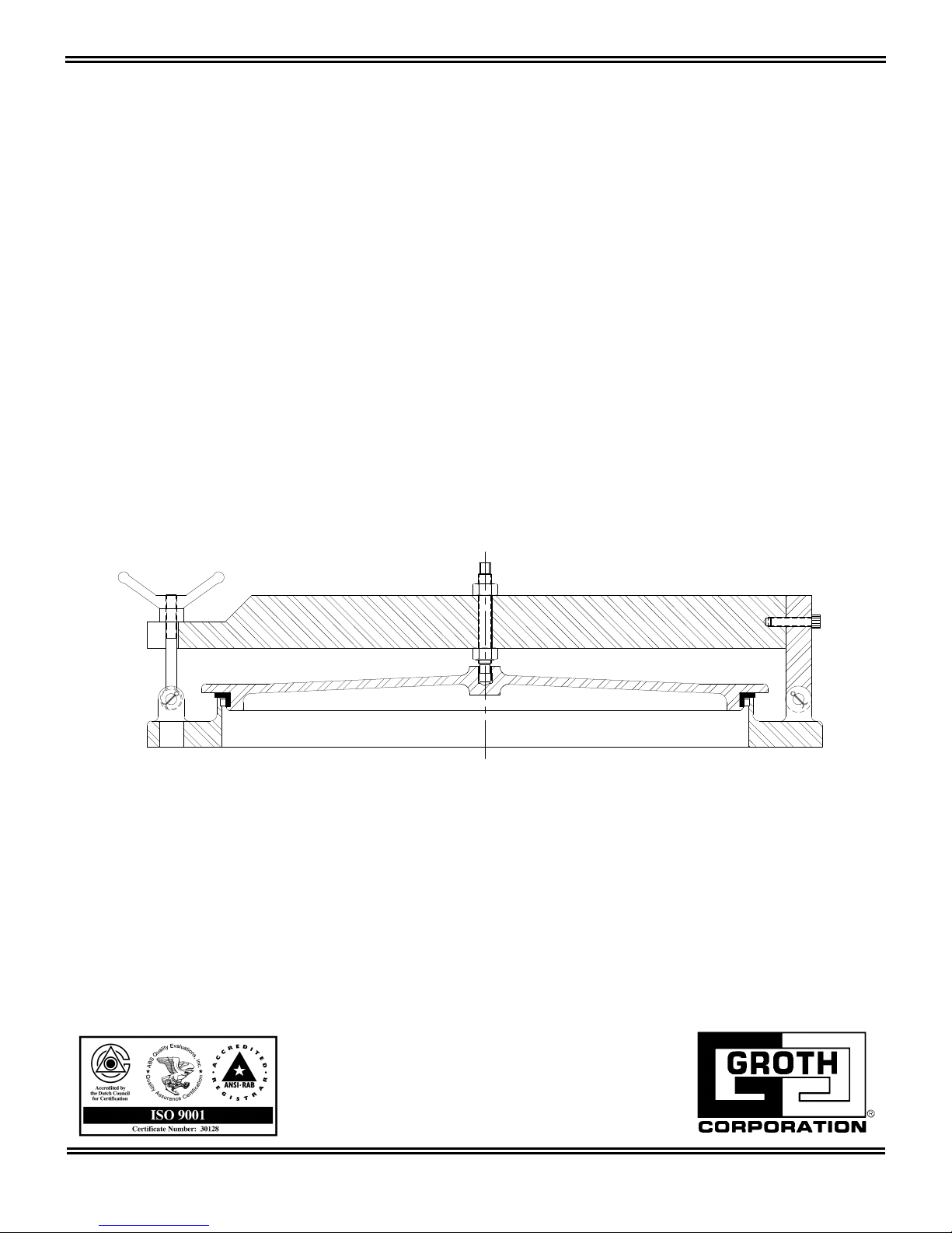
Installation, Operation and Maintenance
Model 8200
IOM 8200.2
April 2006
Page 2
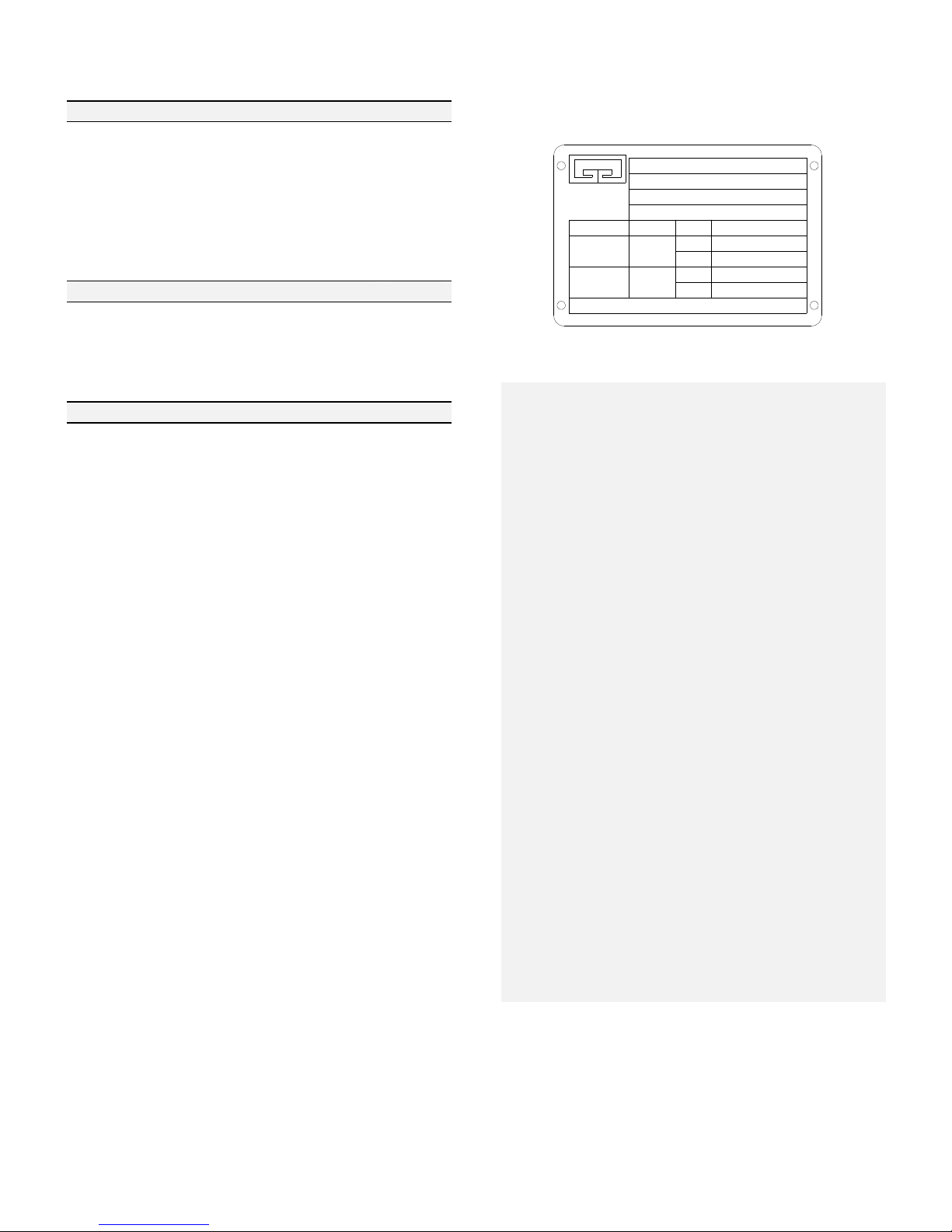
TABLE OF CONTENTS:
DESCRIPTION PAGE
Introduction 2
Safety Warnings 2
Inspection and Storage 3
Installation 3
Operation 4
Maintenance 4
Factory Test and Acceptance Criteria 4
Bill of Materials & Submittal Drawings
Model 8200 5
Abbreviations 5
Model Identification 6
Product Limited Warranty 6
LIST OF TABLES
Table 1 - Bolt Torque (Installation) 3
Table 2 - Spare Parts P/N 4
INTRODUCTION:
This product is used when quick and easy
access to a tank is desired. This product is
generally placed on digester covers or roofs
and is designed to be non-sparking and leak
tight.
The nameplate below shows the basic
information that is listed for each relief valve:
GROTH
CORPORATION
STAFFORD
TEXAS
USA
SETTING
8200-30-1-BO
MD:
S/N: 117405-10-1
TAG:
FLANGE:
PRESS.
A CONTINENTAL DISC COMPANY
TYPE
VAC.
30" IN FF 150
FLOW [SCMH]
% OP
100
100
SAFETY WARNINGS:
This section is an overview of safety
guidelines that should be followed during the
installation, operation and maintenance of
Groth Manhole Covers. To understand the
context of these instructions and warnings, it
is necessary to completely read and
understand the contents of this manual.
The purpose of a manhole cover is to allow
quick and easy access into a tank.
A manhole cover must be carefully
maintained by a qualified technician.
Carefully read and understand this manual
before installing or attempting to repair a
manhole cover. Groth Corporation offers
repair services.
For a list of abbreviations used in this
manual, refer to page 5. For information not
contained in this manual, please contact:
Groth Corporation
13650 N. Promenade Blvd.
Stafford, Texas 77477, USA
(281) 295-6800 (Office)
(281) 295-6999 (Fax)
DO NOT attempt to open the manhole cover
without first bleeding all pressure from the
system.
DO NOT tamper with or modify equipment
from shipped condition. All equipment is
tested, as assembled, prior to shipment and
any modifications will create a potential safety
risk.
The manhole cover has been exposed to
process vapors while in service. Observe all
plant procedures and Material Safety Data
Sheets (MSDS) for the products in the system
when inspecting, adjusting or servicing the
manhole cover. Take appropriate safety
precautions regarding eye protection,
respiration and skin contact.
2
Page 3
INSPECTION AND STORAGE:
The manhole cover is carefully packaged to prevent damage or contamination during shipping.
Inspect all equipment when it is received; report any damage to the carrier immediately. The
manhole cover should be protected during handling and storage. Before installation, inspect the
unit for indications of physical damage. If these are observed, the manhole cover must be
disassembled, cleaned and repaired before installation.
INSTALLATION:
The Model 8200 is a device that must be handled carefully to ensure seat tightness.
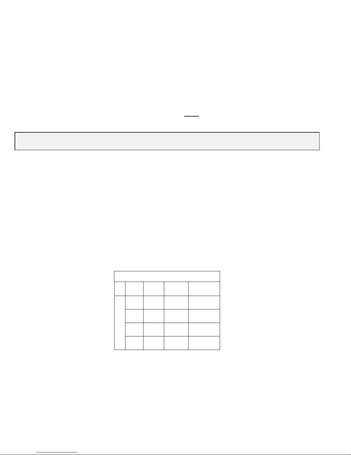
The 8200manhole cover has a flat faced 150# ANSI flange drilling compatibility. Torque
guidelines are listed in Table 1. The manhole cover is NOT
not require high bolting torque. Consult factory for special applications.
WARNING: The manhole cover can be damaged by the over-tightening the studs, uneven
torquing or by mounting on a tank nozzle that is not flat.
The standard Model 8200 manhole cover is furnished with a flat flange; the manhole cover should
be mounted on a flat faced 150# ANSI flange. It is recommended to use a full faced gasket to
avoid deflecting the flange. The connecting flanges must be flat within 0.015" and clean, free of
scratches, corrosion and tool marks.
rated for full flange pressure and does
1. Begin by inspecting the gasket; make sure that the material is suitable for service.
2. Lubricate all studs and nuts with an appropriate thread lubricant. If stainless steel fasteners are
used, select an anti-seize lubricant such as moly-disulfide.
3. Align the gasket with the bolt circle.
4. Set the manhole cover carefully on the nozzle; keep the gasket between the flanges. Install
the studs and tighten nuts hand tight.
5. Torque all fasteners to half the recommended value (see Table 1) in a staggered, alternating
pattern or follow appropriate Plant Maintenance guidelines and standards.
Table 1 : Recommended Torque Values*
Size
20” 20 1.125 75
24” 20 1.250 75
30” 28 1.250 75
150 #ANSI
36” 32 1.500 75
*Note: Torque values are based on a gasket factor m=3.5,
gasket factor y=2000 psi, maximum pressure = 2 psi.
Qty
Holes
Bolt (in)
(UNC)
Torque
(ft-lbs)
6. Make sure that the flanges are not distorted and that the gasket is evenly compressed.
7. Make up the final torque and check that no further nut rotation occurs.
3
Page 4
OPERATION:
1. For inspection or entry into the tank, release and disengage the handle and lift the manhole
cover to full open position. The weight of the cover will keep it open.
WARNING: DO NOT attempt to open the manhole cover without first venting toxic or flammable
fumes or liquids from tank to a safe location to prevent personal injury or property damage.
2. To close the cover, lower slowly into seat, engage handle and tighten until a leak tight seal is
achieved (this occurs when the handle threads bottom out on the eye bolt threads).
WARNING: If the handle is over tightened damage to the manhole cover can occur. DO NOT
tamper with or modify equipment from shipped condition. All equipment is tested, as assembled,
prior to shipment and any modifications will create a potential safety risk.
MAINTENANCE:
Groth Corporation recommends that all service performed on a manhole cover be done at the
factory.
Refer to Fig. 1 on the next page, which illustrates a typical manhole cover when disassembling the
unit.
WARNING: Before disassembling the manhole cover carefully read and understand the Safety
Warnings listed on page 2.
1. Check the metal seating surfaces for pitting, corrosion or product build up. It is recommended
to replace the seal ring (#1). For a list of recommended spare parts see Table 2.
NOTE
: Wipe the seating surface clean before proceeding.
2. Make sure that the manhole cover sits flat on the seat when the handle is tightened. The
handle should be tightened until a leak tight seal is achieved.
WARNING: When assembling a manhole cover do not adjust the center stud (#7). When
assembling the manhole arm do not add hardware between the handle (#5) and the arm (#9).
Adjustment may cause physical damage to components or prevent sealing.
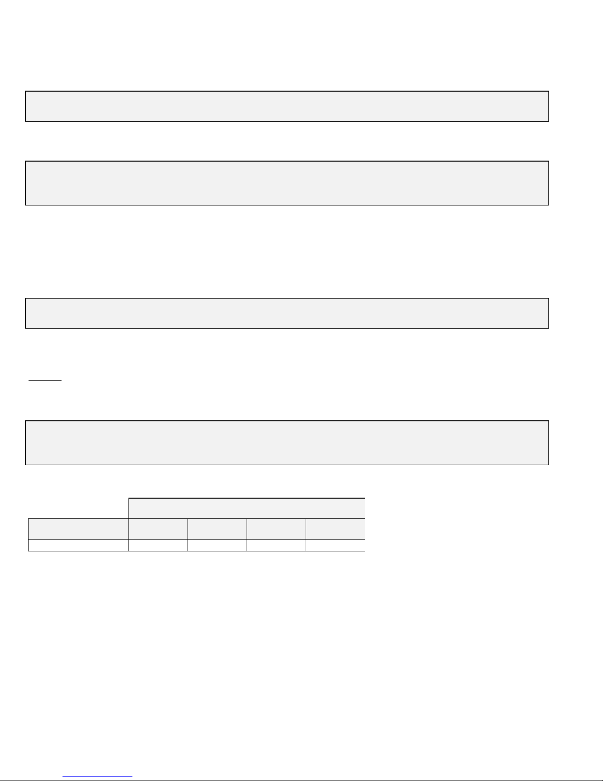
TABLE 2: Part Numbers - Spare Parts *
Valve Size
Component 20” 24” 30" 36"
Seal Ring (Buna N) 1013820B 1013824B 1013830B 1013836B
*Please provide the manhole cover serial number when ordering replacement parts.
FACTORY TEST AND ACCEPTANCE CRITERIA:
1. Pressurize the manhole cover to 1 psig.
2. Test the seat for leaks.
ACCEPTANCE CRITERIA:
3. No visible leaks are acceptable.
4. Complete a Test Report indicating the peak pressure achieved while maintaining a leak tight
seal.
5. A copy of the Test Report shall be maintained with the Valve Maintenance Records.
4
Page 5
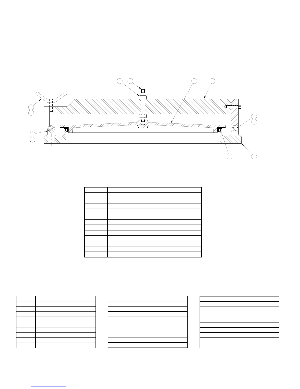
5
4
3
2
LIST OF ABBREVIATIONS
ANSI American National Standard
API American Petroleum Institute
cm Centimeter
ERV Emergency Relief Valve
In. Inches
In. WC Inches Of Water Column
kg Kilogram
kg.m Kilogram-meter
Lb. Pound
Lb.In. Pound Inch
Groth Model 8200 Manhole Cover
6
7 8
Fig. 1
ITEM DESCRIPTION ALUMINUM
1 Seal Ring* Buna-N
2 Cotter Pin SS
3 Front Hinge Pin 304 SS
4 Eye Bolt CS
5 Handle CS
6 Hex Nut CS
7 Stud 316 SS
8 Cover Aluminum
9 Arm Aluminum
10 Body Aluminum
11 Hinge Pin 304 SS
12 Cotter Pin SS
* = Recommended Spare Parts
MAWP M
Max. Maximum
MD Model
mil Thousands Of An Inch
Min. Minimum
mm Millimeter
MSDS Material Safety Data Sheet
OP Over Pressure
OSI Ounces Per Square Inch
OZ Ounces
ax Allowable Working Press.
9
11
12
1 10
P Pressure
P/N Part Number
POV Pilot Operated Valve
PSIG Pounds Per Square Inch
S/N Serial Number
SCFH Standard Cubic Ft Per Hour
SLV Spring Loaded Valve
TVTS Tank Vent Test Stand
V Vacuum
WLV Weight Loaded Valve
5
Page 6
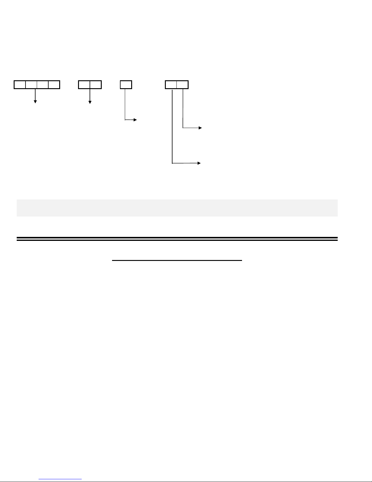
The nameplate on the manhole cover contains the Model Number and Serial Number. The Model
Number contains additional information about materials of construction, soft goods and options.
The following chart will assist in relating the Model Number to the characteristics of your valve:
MODEL SIZE MATERIAL OPTIONS
----- ------
8200 20"
24"
30” Body
36” 1 = Aluminum (standard) Z = Special Options
3 = Carbon Steel O = No Specials
5 = 316 SS
Z = Special
SEAT MATERIAL
B = Buna-N
Z = Special
Teflon® is a registered trademark of E.I. du Pont de Nemours and Co. used under license.
-------------
EXAMPLE: 8200-30-1-BO indicates a 30” Model 8200 with Aluminum construction, Buna-N seal
ring and no special options
.
PRODUCT LIMITED WARRANTY
A. Seller warrants that products which are manufactured by Seller, are manufactured in accordance with published
specifications and free from defects in materials and/or workmanship for a period of (12) twelve months. Seller,
at its option, will repair or replace any products returned intact to the factory, transportation charges prepaid,
which Seller, upon inspection, shall determine to be defective in material and/or workmanship. The foregoing
shall constitute the sole remedy for any breach of Seller's warranty.
B. THERE ARE NO UNDERSTANDINGS, AGREEMENTS, REPRESENTATIONS, OR WARRANTIES, EXPRESS
OR IMPLIED, (INCLUDING MERCHANTABILITY OR FITNESS FOR A PARTICULAR PURPOSE REGARDING
PRODUCTS ) UNLESS SPECIFIED IN THE SALES CONTRACT . THIS CONTRACT STATES THE ENTIRE
OBLIGATION OF SELLER.
Seller makes no warranties, either express or implied, except as provided herein, including without limitation
thereof, warranties as to marketability, merchantability, for a particular purpose or use, or against infringement of
any patent of products. In no event shall Seller be liable for any direct, incidental or consequential damages of
any nature, or losses or expenses resulting from any defective new product or the use of any such product,
including any damages for loss of time, inconvenience, or loss of use of any such product.
C. The original Manufacturer shall be solely responsible for the design, development, supply, production, and
performance of its products hereunder, and the protection of its trade name or names, if any. It assumes no
responsibility, for products modified or changed in any way by its agent or customer. Any such modifications or
changes to products sold by Seller hereunder shall make the product limited warranty null and void.
D. The Manufacturer shall be under no obligation to manufacture, sell, or supply, or to continue to manufacture, sell
or supply any of the Products.
6
 Loading...