

Page 1
INSTALLATION, OPERATION, AND MAINTENANCE
GROTH MODEL 8170 MANOMETER
INSTALLATION:
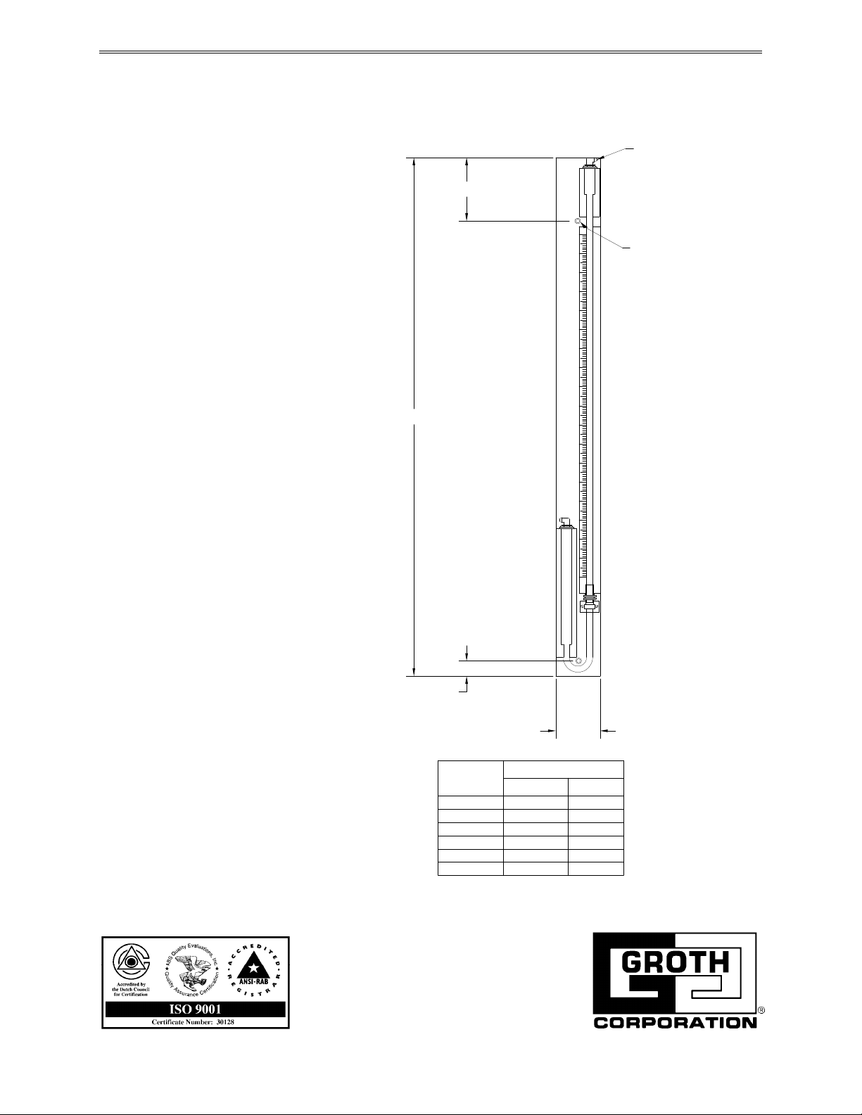
3.56
1. Mount manometer panel on wall
or other suitable support.
2. Connect pressure sensing lines
to manometer wells with
enclosed plastic tubing or 1/4"
copper tubing.
3. Fill with indicating fluid with
specific gravity of 1.0 by
removing pressure connection.
Set scale adjustment to zero.
"A"
OPERATION:
GAGE CONNECTOR
SHUTOFF TYPE
3/16" RUBBER TUBING
(.281) DIA HOLE THRU
2 PLC'S (MOUNTING)
Periodically vent manometer well to
atmosphere and adjust zero point if
required by adjusting scale or
adding fluid.
MAINTENANCE:
Clean tubes and indicator scale as
required. Check pressure
connection for leaks.
NOTICE:
Please specify model number,
serial number and size as shown on
the equipment tag when ordering
replacement parts.
.75
RANGE
0 - 8
0 - 12
0 - 16
0 - 20
0 - 24
0 - 36
NOTE: MAX DEPTH IS 1.50".
RED OIL
16.75
21.88
27.00
32.13
37.19
51.25
2.75
A
WATER
15.19
19.38
23.50
27.56
32.88
43.13
IOM 8170.0
November 1994
 Loading...