

Page 1
Installation, Operation and Maintenance
Manual for Flame Arrester
Models 7618, 7628
©2011 Groth Corporation
IOM-7618
Rev. D 12233
Ref. ID: 96056
Page 2

Page 2 of 16
Table of Contents
I. INTRODUCTION 3
II. INSPECTION AND INSTALLATION 4
1. TABLE 1 – FLAME ARRESTER MAWP 4
2. TABLE 2 – HOUSING AND FLANGE BOLT TORQUE 4
III. MAINTENANCE 6
1. FIGURE 1 – TYPICAL MODEL 7618 FLAME ARRESTER 6
2. TABLE 3 – ELEMENT HOUSING WEIGHT 7
3. TABLE 4 – FLAME ARRESTER ASSEMBLY WEIGHT 7
IV. SPARE PARTS 9
1. TABLE 5 – FLAME BANK ASSEMBLY KIT 10
2. TABLE 6 – GASKET KIT 10
V. MODEL IDENTIFICATION 11
APPENDIX A – MODEL 7618 FLAME ARRESTER (2"-12") 12
APPENDIX B – MODEL 7618 END OF LINE FLAME ARRESTER (2"-12") 13
APPENDIX C – MODEL 7618 FLAME ARRESTER (14" and Larger) 14
APPENDIX D – MODEL 7628 FLAME ARRESTER (2"-12") 15
APPENDIX E – MODEL 7628 FLAME ARRESTER (14"and Larger) 16 15
Page 3

Page 3 of 16
For information not contained in this manual, please contact:
Groth Corporation
13650 N. Promenade Blvd.
Stafford, TX, 77477 USA
Phone: 281-295-6800
Fax: 281-295-6999
www.grothcorp.com
I. INTRODUCTION
Groth Corporation’s flame arresters are designed to inhibit flame propagation in gas piping systems
and to protect low pressure tanks containing flammable liquids. They protect low flash point liquids
from externally caused sources of heat and ignition, providing increased fire protection and safety.
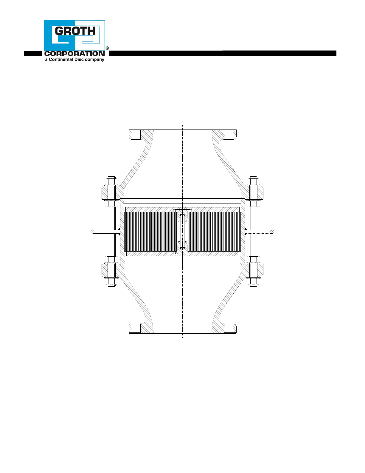
The flame arresters consist of two main components, the arrester bases and the flame element
housing. The bases serve as the connecting interface to the piping system. The housing
accommodates the flame element and is instrumental in stopping the flame passage. The depth of the
flame element absorbs the heat from the vapor flow, cooling the vapor to prevent auto-ignition on the
protected side.
The flame element is comprised of small parallel triangular passageways aligned so that an
approaching flame front is slowed down and then quenched before it can propagate to the protected
side of the device.
Model 7618 and 7628 flame elements utilize spiral wound, crimped ribbon constructed of corrosion
resistant materials, to insure the best flame quenching performance with minimum pressure drop.
Depending on the design of the system in which it is used, the arrester bases can include optional
ports for temperature or pressure monitoring devices. These devices can activate warning or
shutdown systems if abnormal conditions are detected.
A flame arrester should be treated as a safety device and maintained by a knowledgeable repair
technician. Carefully read and understand this Manual before installing or servicing this product.
Page 4
The MAWP is different
from the approved preignition pressure.
Consult the factory for
pre-ignition pressure
limits for your
installation.
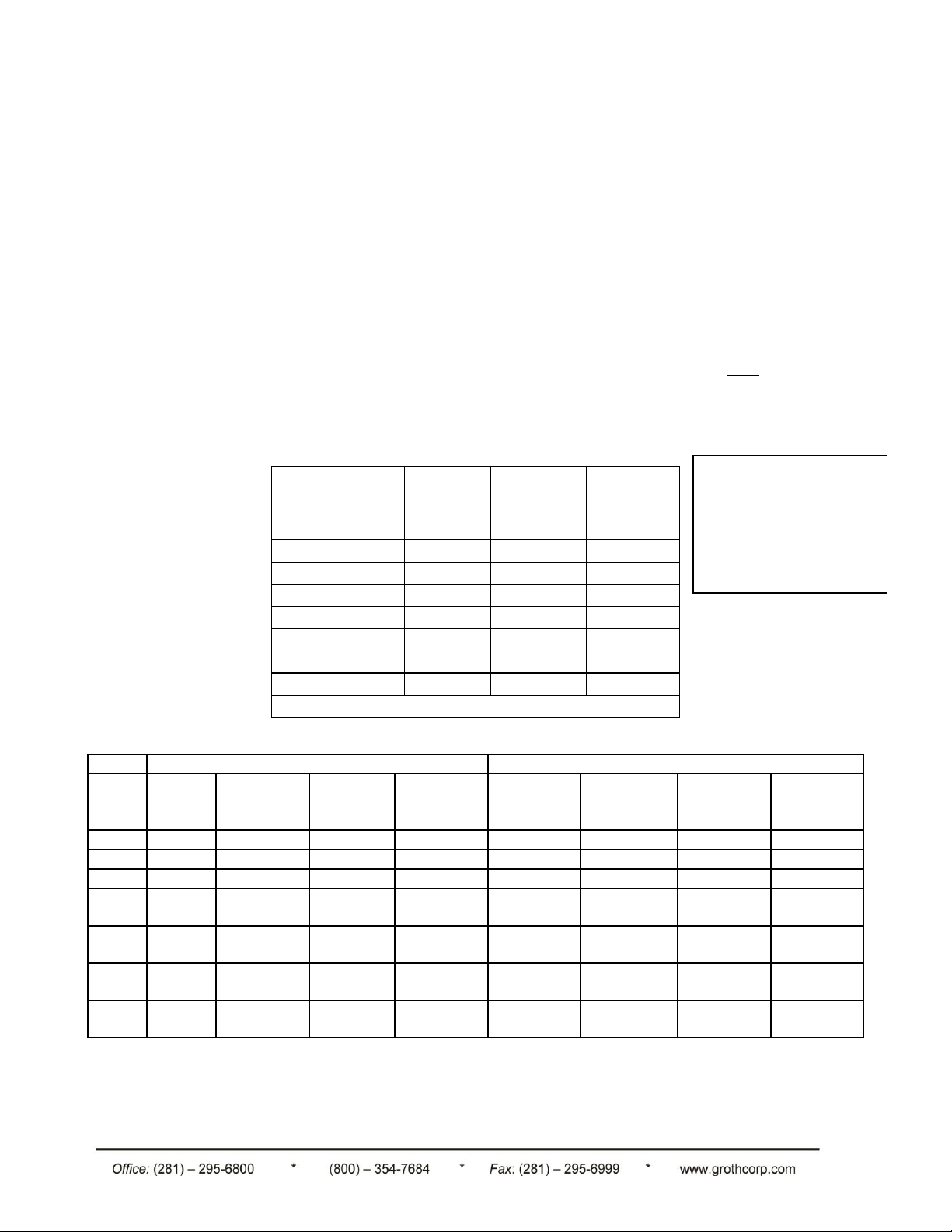
II. INSPECTION AND INSTALLATION
Size
Model
7618
Alum
Model
7618
CS/SS
Model
7628 Alum
Model
7628
CS/SS
2"
50 (345)
100 (690)
150 (1034)
275 (1965)
3"
50 (345)
100 (690)
140 (965)
275 (1965)
4"
50 (345)
100 (690)
140 (965)
275 (1965)
6"
50 (345)
100 (690)
140 (965)
275 (1965)
8"
50 (345)
100 (690)
90 (620)
200 (1379)
10"
50 (345)
100 (690)
75 (482)
150 (1034)
12"
50 (345)
100 (690)
75 (482)
150 (1034)
Sizes > 12" (7618 & 7628): MAWP = 15 PSIG
Flange*
Housing
Size
Raised
Face
Steel
Raised
Face
Aluminum
Flat
Face
Steel
Flat Face
Aluminum
Model
Steel 7618
Model
Steel 7628
Aluminum
Housing
7618
Aluminum
Housing
7628
2"
60 (82)
35 (47)
60 (82)
50 (68)
60 (82)
40 (54)
50 (68)
35 (47)
3"
60 (82)
35 (47)
60 (82)
50 (68)
60 (82)
40 (54)
50 (68)
35 (47)
4"
60 (82)
35 (47)
60 (82)
50 (68)
60 (82)
40 (54)
50 (68)
35 (47)
6"
105
(143)
60 (81)
105 (143)
90 (122)
105 (143)
105 (143)
90 (122)
90 (122)
8"
105
(143)
60 (81)
105 (143)
90 (122)
105 (143)
105 (143)
90 (122)
90 (122)
10"
140
(190)
100 (136)
170 (231)
140 (190)
170 (231)
220 (300)
140 (190)
170 (231)
12"
140
(190)
100 (136)
170 (231)
140 (190)
170 (231)
220 (300)
140 (190)
170 (231)
All Groth Corporation's flame arresters are bi-directional and the installation on a tank or piping system
depends to a great extent on the design of the system. The Model 7618 is recommended for vertical
installation in closed piping systems or venting to atmosphere. If a Model 7618 is installed in a
horizontal line, it should be equipped with drain ports for removal of condensation from the housing.
WARNING: Do not pipe both drainage connections to a common line as
this can provide a passage for flame to by-pass the flame arrester element.
The Model 7628 is designed for either vertical or horizontal installation.
These series of flame arresters have 150# ANSI PN 10 OR PN 16 flange drilling compatibility, [30" &
36" model 7618 & 7628 have API 650 drilling], and are pneumatically tested to 15 PSIG at the factory.
Follow the guidelines listed in Table 2 for flange make-up torque. The arresters are NOT rated for full
flange pressure and do not require high bolting torque. Recommended torque values are based on
pressures [MAWP] in Table 1. Consult factory for higher pressure applications.
Note:
TABLE 1: FLAME ARRESTER MAWP [PSIG (kPa)]
Page 4 of 16
*Torque values are for reference only and based on a nitrile binder synthetic gasket,
1/16" thick and unlubricated threads.
TABLE 2: BOLT TORQUE [ft-lbs (Nm)]
Page 5

Page 5 of 16
The following guidelines should be observed at installation:
WARNING: Groth Corporation's flame arresters have been tested by
Factory Mutual Research. To maintain the approval classification, all
arresters must be installed within 10 pipe diameters of the open end of the
vent pipe.
1. Remove any flange protectors and discard all packing material. Inspect flange faces and flame
element for damage or contamination.
2. Inspect the gasket seating surface of the tank nozzle or piping. It must be clean, flat, free of
scratches, corrosion and tool marks.
3. Aluminum flame arresters are furnished with flat face flanges; they should only be installed on
a mating flat face flange with a full face gasket.
WARNING: Installation of an aluminum arrester in piping with raised face
flanges can cause permanent distortion of the base flanges. This may
result in vapor leakage at the flange connection.
Adjacent piping must have appropriate structural support to prevent
excessive loads on the flame arrester flanges.
4. Inspect the gasket; make sure that the material is suitable for the application. Center the
gasket within the bolt circle.
5. Set the arrester between its mating flanges or on the nozzle. Position the lifting handles and
jacking nuts to facilitate future removal of the flame arrester housing (See Maintenance
Instructions section). Install the studs and tighten nuts hand tight.
WARNING: The handles on the arrester housing are to be used for
handling the element only during inspection and maintenance. DO NOT
use the handles to lift the entire flame arrester assembly.
Notes:
When installing Model 7628 in the horizontal position, the
eccentric portion of the housing must be positioned
upward (See Page 14). In this position condensation will
tend to move in the direction of flow and not collect in the
element.
Leave space behind mating pipe flange for insertion of
studs, as there may not be sufficient space to insert studs
from the flame arrester side.
6. Torque all fasteners to half the value listed in Table 2 in a staggered, alternating pattern to
provide an evenly compressed gasket joint.
7. Make up the final torque and check that no further nut rotation occurs at the specified torque
value.
Page 6

WARNING: After installation, all connections must be inspected for vapor
leakage. This may be accomplished by static pressure test, gas detector,
or "bubble" test using a liquid leak detector.
III. MAINTENANCE
For maximum operating efficiency the element of a flame arrester must be inspected for clogging at
regular intervals. Frequency of inspection and maintenance should be based on the experience
gained in each application. For ease of service, the flame element housing can be easily removed for
inspection and maintenance without removing the arrester from the line. It is recommended that the
arrester be removed for inspection of the element at least once per year or any time that one of the
following conditions occurs:
Excessive pressure drop is encountered at a known flow rate.
A flame front is detected.
Note:
Flame arresters equipped with a steam jacket can not be serviced in-line. The
arrester must be removed from the pipeline or tank nozzle for inspection and
maintenance.
1. Purge the line or tank with an inert gas before attempting to remove the arrester for maintenance.
CAUTION: The connecting pipeline must be free of all hazardous or flammable vapors before
inspection procedures begin. Before disassembling consult Material Safety Data Sheets
(MSDS) for all products that were exposed to in service. The components should be cleaned
according to MSDS procedures. Take appropriate safety precautions regarding eye protection,
skin contact & respiration.
2. Refer to Fig. 1 which illustrates a typical flame arrester with the element removed.
Page 6 of 16
FIGURE 1 - TYPICAL MODEL 7618 FLAME ARRESTER
Page 7

3. Loosen the housing nuts and remove only those studs necessary to withdraw the housing. Do not
Models 7618 / 7628
Size
Aluminum
Alum/SS
Steel
2"
5 (2)
10 (5)
15 (7)
3"
10 (5)
10 (5)
20 (9)
4"
15 (7)
20 (9)
35 (16)
6"
30 (14)
45 (20)
75 (34)
8"
45 (20)
70 (32)
115 (52)
10"
70 (32)
110 (50)
175 (80)
12"
95 (43)
160 (73)
250 (114)
Models 7618
Models 7628
Size
Aluminum
Alum/SS
Steel
Size
Aluminum
Alum/SS
Steel
2"
15 (7)
20 (9)
45 (70)
2"
25 (11)
30 (14)
70 (32)
3"
25 (11)
30 (14)
75 (34)
3"
35 (16)
40 (18)
95 (43)
4"
40 (18)
45 (20)
105 (48)
4"
50 (23)
60 (27)
105 (48)
6"
80 (36)
100 (45)
225 (102)
6"
85 (39)
100 (45)
225 (102)
8"
130 (59)
155 (70)
360 (164)
8"
150 (68)
175 (80)
360 (164)
10"
200 (91)
245 (111)
555 (252)
10"
235 (107)
280 (127)
555 (252)
12"
285 (130)
345 (157)
795 (361)
12"
320 (125)
385 (175)
795 (361)
remove studs with spreader nuts.
WARNING: The handles on the arrester housing are to be used for
handling the element only during inspection and maintenance. DO NOT
use the handles to lift the entire flame arrester assembly.
4. If the flame arrester is in a horizontal line, attach whatever lifting equipment is required to remove the
element [see weight table 3].
TABLE 3 - ELEMENT HOUSING WEIGHT [Lb. (kg)]
Page 7 of 16
TABLE 4 - FLAME ARRESTER ASSEMBLY WEIGHT [Lb. (kg)]
WARNING: If not supported, the element housing will drop onto the
remaining studs when the bases are separated. Be careful to avoid contact
with the housing while separating the bases.
Page 8

Page 8 of 16
5. On the remaining studs, loosen the housing nuts incrementally while advancing the spreader nuts to
separate the bases. When the bases are separated sufficiently to remove the housing, tighten the
housing nuts so the bases form a rigid assembly when the housing is removed.
6. If a vertically mounted flame arrester is used to support a relief valve or similar equipment, tightening
the housing nuts after separating the bases will provide sufficient support for the relief valve.
7. Remove the housing assembly for inspection. Visually inspect the flame element and supporting grids
for damage or corrosion build-up from both sides. If the flame element appears to be damaged, it
should be replaced immediately.
WARNING: Failure to replace a damaged flame element can render the flame arrester ineffective
8. Verify that the element openings are not clogged by viewing a light source through the element
passages. If the flame element is dirty or clogged it can be cleaned by one of the following methods:
Compressed air
High pressure steam or water purge
Solvent wash followed by compressed air
WARNING: Never try to clean the element by inserting a sharp tool or
probe into the orifices. Any damage to the integrity of these passages can
render the flame arrester ineffective.
CAUTION: If compressed air, steam, or high pressure water jet is used to
clean clogged element passageways, restrict access to the area to prevent
injury from blown debris exiting the element. Use appropriate personal
safety equipment for the cleaning method used.
TIP: The best method of cleaning and frequency should be based on the
experience gained in each application.
9. Inspect the sealing gasket for damage and replace if necessary. (See Table 6 for replacement gasket
part numbers.
10. Install a gasket in the counter bore of each base. Position the element housing to align with the
counterbores. Insert the studs and torque all fasteners to half the value listed in Table 2 in a
staggered, alternation pattern to provide an evenly compressed gasket joint.
If the arrester is in high temperature service or stainless steel external studs and nuts are used, apply
an anti-seize compound such as moly-disulfide to all threaded components.
11. Make up the final torque and check that no further nut rotation occurs at the specified torque value.
The torque values are based on original gaskets supplied by Groth Corporation.
Page 9

IV. SPARE PARTS
Size
Housing
Material
Element
Material
Kit P/N
Size
Housing
Material
Element
Material
Kit P/N
2"
Aluminum
Aluminum
KFB76180211
8"
Carbon Steel
Aluminum
KFB76180831
3"
Aluminum
Aluminum
KFB76180311
10"
Carbon Steel
Aluminum
KFB76181031
4"
Aluminum
Aluminum
KFB76180411
12"
Carbon Steel
Aluminum
KFB76181231
6"
Aluminum
Aluminum
KFB76180611
2"
Carbon Steel
316 SS
KFB76180235
8"
Aluminum
Aluminum
KFB76180811
3"
Carbon Steel
316 SS
KFB76180335
10"
Aluminum
Aluminum
KFB76181011
4"
Carbon Steel
316 SS
KFB76180435
12"
Aluminum
Aluminum
KFB76181211
6"
Carbon Steel
316 SS
KFB76180635
2"
Aluminum
316 SS
KFB76180215
8"
Carbon Steel
316 SS
KFB76180835
3"
Aluminum
316 SS
KFB76180315
10"
Carbon Steel
316 SS
KFB76181035
4"
Aluminum
316 SS
KFB76180415
12"
Carbon Steel
316 SS
KFB76181235
6"
Aluminum
316 SS
KFB76180615
2"
316 SS
316 SS
KFB76180255
8"
Aluminum
316 SS
KFB76180815
3"
316 SS
316 SS
KFB76180355
10"
Aluminum
316 SS
KFB76181015
4"
316 SS
316 SS
KFB76180455
12"
Aluminum
316 SS
KFB76181215
6"
316 SS
316 SS
KFB76180655
2"
Carbon Steel
Aluminum
KFB76180231
8"
316 SS
316 SS
KFB76180855
3"
Carbon Steel
Aluminum
KFB76180331
10"
316 SS
316 SS
KFB76181055
4"
Carbon Steel
Aluminum
KFB76180431
12"
316 SS
316 SS
KFB76181255
6"
Carbon Steel
Aluminum
KFB76180631
Size
Part No.
2"
KS761802
3"
KS761803
4"
KS761804
6"
KS761806
8"
KS761808
10"
KS761810
12"
KS761812
Synthetic-Non-Asbestos Fiber sheet material with
a nitrile binder. For special applications or chemical
compatibility please contact factory.
Flame Bank Kits are available upon request. Kits include the flame arrester element and two nonasbestos gaskets. Kits are based on Model Number, Size, and Material. The kits only apply to
arresters manufactured since 1992; consult factory for sizes greater than 12". To procure appropriate
kit, please contact Groth Corporation with the Serial Number, Model Number, Size, and Material.
TABLE 5 – FLAME BANK ASSEMBLY KITS
Page 9 of 16
.
TABLE 6 - GASKET KIT PART NUMBERS
Page 10

Page 10 of 16
-----
------
-------------
V. MODEL NUMBER IDENTIFICATION
The nameplate on the Flame Arrester contains the Model Number, Serial Number, set pressures and
flow capacity at a specified over-pressure. The Model Number contains additional information about
materials of construction, soft goods and options. The following chart will assist in relating the Model
Number to the characteristics of your valve:
7618 02 Element O = No Specials
7628 03 1=Aluminum Z = Special Option
04 Body 5=316 SS O = No Jacket
06 1=Aluminum Z=Special J = Steam Jacket
08 3=CS
10 5=316 SS
12 Z=Special
F = Flanged Outlet
W = Weatherhood
EXAMPLE: Model 7618-04-11-FOO indicates a 4" Model 7618 with an Aluminum body an Aluminum flame
element, flanged inlet/outlet connections, and no special options.
Page 11

Page 11 of 16
ITEM DESCRIPTION
STANDARD MATERIALS OF CONSTRUCTION
ALUMINUM
CARBON STL
316 SS
1
BASE
AL (356 T6)
CS (WCB)
316 SS (CF-8M)
2
HANDLE
ALUM
CS
SS
3 SPREADER HEX NUT
SS
SS
SS
4
HEX NUT
SS
SS
SS
5
STUD
SS
SS
SS
6
ELEMENT PLUG
SS
SS
303 SS
7
ELEMENT ROD
SS
SS
316 SS
8
ELEMENT GRID
ALUM
316 SS
316 SS
9 * ELEMENT HOUSING
ALUM
CS
316 SS
10 PIPE PLUG (OPTIONAL)
ALUM
CS
316 SS
11 COUPLING (OPTIONAL)
ALUM
CS
316 SS
12
*
GASKET
NON-ASB
NON-ASB
NON-ASB
13 * FLAME ELEMENT
ALUM (1)
316 SS
316 SS
APPENDIX A: Model 7618 Flame Arrester (2"-12")
(1) Available in 316 SS
* Recommended Spare Parts
Page 12

Page 12 of 16
ITEM DESCRIPTION
STANDARD MATERIALS OF CONSTRUCTION
ALUMINUM
CARBON STL
316 SS
1
BASE
AL (356 T6)
CS (WCB)
316 SS (CF-8M)
2
HANDLE
ALUM
CS
SS
3
HEX NUT
SS
SS
SS
4
STUD
SS
SS
SS
5
ELEMENT PLUG
SS
SS
303 SS
6
ELEMENT ROD
SS
SS
316 SS
7
ELEMENT GRID
ALUM
316 SS
316 SS
8 * ELEMENT HOUSING
ALUM
CS
316 SS
9 COUPLING (OPTIONAL)
ALUM
CS
316 SS
10 PIPE PLUG (OPTIONAL)
ALUM
CS
316 SS
11
*
GASKET
NON-ASB
NON-ASB
NON-ASB
12 * FLAME ELEMENT
ALUM (1)
316 SS
316 SS
13
EYE NUT
CS
CS
316 SS
14
HEX NUT
SS
SS
SS
15 WEATHERHOOD
ALUM
CS
316 SS
16
BIRD SCREEN
SS
SS
SS
17 ADAPTER PLATE
CS
CS
316 SS
APPENDIX B: Model 7618 End-of-Line Flame Arrester (2"-12")
(1) Available in 316 SS
* Recommended Spare Parts
Page 13

APPENDIX C: Model 7618 Flame Arrester (14" and Larger)
ITEM DESCRIPTION
STANDARD MATERIALS OF CONSTRUCTION
ALUMINUM
CARBON STL
316 SS
1
BASE
AL (356 T6)
CS (WCB)
316 SS (CF-8M)
2
SPACER
ALUM
CS
316 SS
3 * FLAME ELEMENT
ALUM (1)
316 SS
316 SS
4 * ELEMENT HOUSING
ALUM
CS
316 SS
5
STUD
SS
SS
SS
6
HEX NUT
SS
SS
SS
7
ELEMENT GRID
ALUM
316 SS
316 SS
8 ELEMENT SHAFT
SS
SS
316 SS
9
*
GASKET
NON-ASB
NON-ASB
NON-ASB
10
LIFTING LUG
ALUM
CS
316 SS
11 PIPE PLUG (OPTIONAL)
ALUM
CS
316 SS
12 COUPLING (OPTIONAL)
ALUM
CS
316 SS
13 SPREADER HEX NUT
SS
SS
SS
Page 13 of 16
(1) Available in 316 SS
* Recommended Spare Parts
Page 14

Page 14 of 16
ITEM DESCRIPTION
STANDARD MATERIALS OF CONSTRUCTION
ALUMINUM
CARBON STL
316 SS
1
BASE
AL (356 T6)
CS (WCB)
316 SS (CF-8M)
2
*
GASKET
NON-ASB
NON-ASB
NON-ASB
3 * FLAME ELEMENT
ALUM (1)
316 SS
316 SS
4
ELEMENT PLUG
SS
SS
303 SS
5
ELEMENT ROD
SS
SS
316 SS
6
HANDLE
ALUM
CS
SS
7 SPREADER HEX NUT
SS
SS
SS
8 PIPE PLUG (OPTIONAL)
ALUM
CS
316 SS
9
HEX NUT
SS
SS
SS
10
STUD
SS
SS
SS
11 COUPLING (OPTIONAL)
ALUM
CS
316 SS
12
ELEMENT GRID
ALUM
316 SS
316 SS
13 * ELEMENT HOUSING
ALUM
CS
316 SS
APPENDIX D: Model 7628 Flame Arrester (2"-12”)
(1) Available in 316 SS
* Recommended Spare Parts
Page 15

Page 15 of 16
ITEM DESCRIPTION
STANDARD MATERIALS OF CONSTRUCTION
ALUMINUM
CARBON STL
316 SS
1 * ELEMENT HOUSING
ALUM
CS
316 SS
2
BASE
AL (356 T6)
CS (WCB)
316 SS (CF-8M)
3 * FLAME ELEMENT
ALUM (1)
316 SS
316 SS
4 COUPLING (OPTIONAL)
ALUM
CS
316 SS
5 RETAINER ELEMENT
ALUM
316 SS
316 SS
6 ELEMENT SHAFT
SS
316 SS
316 SS
7
STUD
SS
SS
SS
8
HEX NUT
SS
SS
SS
9
*
GASKET
NON-ASB
NON-ASB
NON-ASB
10
LIFTING LUG
ALUM
CS
316 SS
11 PIPE PLUG (OPTIONAL)
ALUM
CS
316 SS
12
GUIDE ROLLER
ALUM
CS
316 SS
APPENDIX E: Model 7628 Flame Arrester (14" and Larger)
(1) Available in 316 SS
* Recommended Spare Parts
Page 16

Page 16 of 16
 Loading...