

Page 1
Installation, Operation and Maintenance Manual
For Model 3011L/3041L & 3011H/3041H &
3011HP/3041HP Blanket Gas Regulators
IOM-3011.2
Rev. B 12541
Ref. I.D.: 98191
© 2008, 2014 Groth Corporation
Page 2

TABLE OF CONTENTS:
INTRODUCTION: ................................................................................................................................................................................... 2
DESIGN, FUNCTION & OPERATION .................................................................................................................................................... 2
FIGURE 1: MODEL 3011L - SHUT-OFF CONDITION .......................................................................................................................... 2
FIGURE 2: MODEL 3011H - FLOWING CONDITION ........................................................................................................................... 2
FIGURE 3: TYPICAL TANK INSTALLATION ....................................................................................................................................... 3
TABLE 1: MODEL 3011/3041 SPECIFICATIONS ................................................................................................................................ 3
GENERAL SAFETY INSTRUCTIONS ................................................................................................................................................... 4
SAFETY WARNINGS ............................................................................................................................................................................. 4
INSPECTION AND INSTALLATION ...................................................................................................................................................... 5
MODEL SELECTION AND PRESSURE SETTING ............................................................................................................................... 6
TABLE 2 – SET PRESSURE RANGES ................................................................................................................................................. 6
TABLE 3 – SPRING SELECTION .......................................................................................................................................................... 7
TABLE 4 – FLOW CAPACITY SETTING ............................................................................................................................................... 9
TABLE 5 – ORIFICE SLEEVE POSITION ............................................................................................................................................. 9
BLANKETING THE TANK ..................................................................................................................................................................... 9
TROUBLESHOOTING GUIDE ............................................................................................................................................................. 10
PREVENTIVE MAINTENANCE ............................................................................................................................................................ 10
RECOMMENDED SPARE PARTS ...................................................................................................................................................... 10
TABLE 6 – SOFT GOODS KITS .......................................................................................................................................................... 10
DISASSEMBLY .................................................................................................................................................................................... 11
FIGURE 4: SPRING CHAMBER ASSEMBLY .................................................................................................................................... 11
FIGURE 5: PISTON/BODY ASSEMBLY ............................................................................................................................................. 11
FIGURE 6: EXPLODED PISTON ASSEMBLY ................................................................................................................................... 12
FIGURE 7: ACTUATOR LINKAGE ASSEMBLY ................................................................................................................................ 12
ASSEMBLY .......................................................................................................................................................................................... 12
TABLE 7 – RECOMMENDED BOLT TORQUE ................................................................................................................................... 13
FIGURE 8: ORIFICE SLEEVE ORIENTATION ................................................................................................................................... 13
FIGURE 9: EXPLODED PISTON ASSEMBLY ................................................................................................................................... 13
FIGURE 10: PISTON/BODY ASSEMBLY ........................................................................................................................................... 13
TESTING AND SETTING PROCEDURE ............................................................................................................................................. 14
FIGURE 11: TEST SET-UP ................................................................................................................................................................. 14
FIGURE 12: CROSS SECTIONAL ASSEMBLY ................................................................................................................................. 15
BILL OF MATERIAL ............................................................................................................................................................................ 16
HOW TO ORDER ................................................................................................................................................................................. 21
PRODUCT LIMITED WARRANTY ....................................................................................................................................................... 21
Page 3

INTRODUCTION:
The blanket gas regulator is one of the principal components typically installed on a storage tank to protect the tank and its
contents. It is a precision regulator that is capable of maintaining a very low gas pressure (1/2" WC minimum) in the tank by
controlling the flow of a high pressure (200 PSI maximum) blanketing gas. It maintains a positive tank pressure when fluid is
pumped out or as fluid temperature decreases.
Typically nitrogen or another compatible gas is used to suppress the tank product vapors. This reduces losses due to product
evaporation and prevents atmospheric contaminants, including moisture, from entering the tank, preventing tank corrosion and
product contamination. The use of an inert blanketing gas minimizes air pollution due to leakage or eme r gency venting.
In addition to the blanketing regulator, a tank must be protected from structural damage by pressure and vacuum relief valves. A
typical tank installation is shown in Figure 3, which includes the regulator, a pressure vacuum relief valve and an emergency
pressure relief valve. Groth Corporation manufacturers all of these devices.
The regulator must be maintained by a knowledgeable valve technician. It should only be assembled under clean conditions,
preferably in a shop environment. Carefully read and understand this manual before attempting to adjust set pressure or flow
capacity, or repair the regulator.
For information not contained in this manual, please contact:
Groth Corporation
13650 N. Promenade Blvd
Stafford, TX 77477
281-295-6800 (Phone)
281-295-6995 (Fax)
DESIGN, FUNCTION & OPERATION
The Groth Model 3011L, 3011H, 3011HP, 3041L, 3041H, & 3041HP Regulators are high capacity, spring operated, diaphragm
type, balanced piston regulators, designed for tank blanketing applications.
The regulator controls the flow of blanketing gas to the vapor space in the storage tank. When the internal pressure of the tank is
at or above set pressure, the diaphragm force exceeds the spring force and the regulator is shut off bubble tight. When the tank
pressure falls below the set point, the spring force opens the regulator and blanket gas flows into the tank (See Figures 1 and 2).
FIGURE 1: MODEL 3011L - SHUT-OFF CONDITION FIGURE 2: MODEL 3011H - FLOWING CONDITION
2
Page 4

The regulator must be sized to provide sufficient blanket gas to prevent the loss of tank pressure due to liquid discharge or
decreased ambient temperature. Table 4 lists the maximum flow capacity of the regulator for various blank eting gases. Actual
system flow will depend on supply system piping, tank connection piping and positio n of the internal orifice sleeve. Set pressure is
the pressure at which the regulator begins flowing when tank pressure is decreasing and stops flowing when tank pressure is
increasing.
This manual is intended to provide recommended procedures and practices for installati on, operation, and maintenance of the
Groth MODEL 3011L, 3011H, 3011HP, 3041L, 3041H and 3041HP Regulators. An y standard procedures and practices developed
for a specific plant or process should supersede this manual. While this manual cannot cover all possible contingencies, following
these guidelines should provide safe, reliable regulator performance.
Note: Throughout this manual, the item numbers are listed in [ ] after the part description. These item numbers refer to the Bill of
Materials (Page 14) and various drawings of the regulator and its sub-assemblies (Figures 4 through 10). While the size and
appearance of the actuators differs between the 3011L and 3011H, the item identification and descr iption of the components are
identical.
FIGURE 3: TYPICAL TANK INSTALLATION
TABLE 1: MODEL 3011/3041 SPECIFICATIONS
SIZE 1/2" 1"
Inlet/Outlet connection size 1/2" 1"
Maximum supply pressure 200 PSI 200 PSI
Actuator Housing MAWP 8 PSI 8 PSI
3
Page 5

GENERAL SAFETY INSTRUCTIONS
This section is intended as an overview of safety guidelines that should be followed during the installation, operation and
maintenance of the Groth model 3011L, & 3041L, 3011H & 3041H, 3011HP & 3041HP Blanket Gas Reg ulators. To understand
the context of these warnings and instructions, read and understand this complete manual.
The blanket gas regulator is one of the principal protection devices typically installed on a product storage tank. It is a precision
regulator that is designed to maintain a positive pressure on the tank. This will prevent product loss or contamination from
atmospheric air when pumping liquid out or when the stored fluid cools.
The blanket gas regulator should not be used as a substitute for a vacuum relief valve. An interruption in the blanket gas supply
could cause tank failure.
SAFETY WARNINGS
IN THE EVENT OF AN ACTUATOR OR PISTON DIAPHRAGM FAILURE, THE REGULATOR WILL FAIL IN THE OPEN
POSITION. GAS FLOW WILL NOT BE SHUT OFF. EMERGENCY AND OR PRESSURE/VACUUM RELIEF VALVES MUST BE
SIZED TO INCLUDE BLANKET GAS REGULATOR CAPACITY IN ADDITION TO NORMAL AND EMERGENCY VENTING
REQUIREMENTS.
IN THE EVENT OF BLANKET GAS SUPPLY FAILURE, THE REGULATOR WILL NOT PROTECT THE TANK FROM AN
EXCESS VACUUM CONDITION. BLANKET GAS SUPPLY FAILURE SHOULD BE CONSIDERED IN THE SIZING,
SELECTION AND SETTING OF PRESSURE/VACUUM RELIEF VALVES.
BLANKET GAS REGULATOR FLOW CAPACITY IS BASED ON A KNOWN SUPPLY PRESSURE AND A PROPERLY SIZED
GAS DISTRIBUTION SYSTEM.
ALL SUPPLY PIPING MUST BE FREE OF WELD SLAG AND OTHER DEBRIS BEFORE INSTALLING THE BLANKET GAS
REGULATOR. IF WELD SLAG OR DEBRIS FLOWS THROUGH THE REGULATOR THERE IS A HIGH POTENTIAL FOR
SEATING SURFACE AND O-RING DAMAGE. THIS TYPE OF DAMAGE WILL CAUSE THE REGULATOR TO CONSTANTLY
FLOW BLANKETING GAS TO THE TANK. TO PREVENT DAMAGE FROM WELD SLAG OR DEBRIS CONSIDER
INSTALLING AN UPSTREAM FILTER OR STRAINER. AN ENGINEERING ANALYSIS MUST BE PERFORMED TO
EVALUATE THE EFFECT THESE DEVICES MAY HAVE ON THE BLANKET GAS REGULATOR FLOW CAPACITY.
THE REGULATOR IS NORMALLY FACTORY SET AT THE DESIRED SET PRESSURE. THE SPRING RANGE IS STAMPED
ON THE NAMEPLATE. DO NOT ATTEMPT TO RE-ADJUST THE SET PRESSURE BEYOND THE LIMITS SPECIFIED IN
TABLE 3.
THE REGULATOR IS TO BE CONNECTED TO THE TANK OR VESSEL WITH A MINIMUM 0.31" ID TUBING SENSE LINE.
THIS LINE MUST BE KEPT OPEN AND UNOBSTRUCTED TO ENSURE THAT THE REGULATOR SENSES THE ACTUAL
TANK PRESSURE. LONG SENSE LINES MAY REQUIRE A LARGER DIAMETER AND CARE MUST BE TAKEN TO ASSURE
THAT THE LINE IS SELF-DRAINING. FOR SOME APPLICATIONS, A NITROGEN PURGE MAY BE REQUIRED TO ENSURE
THAT THIS LINE REMAINS OPEN. CONSULT FACTORY FOR RECOMMENDATIONS.
DO NOT ATTEMPT TO REMOVE THE REGULATOR FROM THE LINE OR PERFORM FIELD REPAIRS IN LINE WITHOUT
FIRST ISOLATING THE REGULATOR FROM BOTH THE TANK AND THE SUPPLY GAS LINE. BLEED ALL PRESSURE
BEFORE REMOVING THE SPRING BONNET OR THE FLOW ORIFICE LOCKING SCREW, OR OPENING UP THE
ACTUATOR HOUSINGS.
NOTE THE ORIFICE SLEEVE POSITION WHEN DISASSEMBLING THE REGULATOR. IT WAS FACTORY SET ACCORDING
TO THE FLOW REQUIREMENTS LISTED ON THE ORDER AND MUST BE RE-INSTALLED IN THE SAME POSITION TO
ENSURE THE CORRECT FLOW.
THE REGULATOR BODY AND ACTUATOR HOUSING ARE EXPOSED TO PROCESS VAPORS. OBSERVE ALL SAFETY
PRECAUTIONS AS SPECIFIED ON THE MATERIAL SAFETY DATA SHEET FOR THE PRODUCTS THAT ARE IN THE TANK.
THE VENTS ON THE SPRING BONNET AND ACTUATOR HOUSING MUST BE CLEAN AND OPEN TO THE ATMOSPHERE
AND SHOULD BE INSPECTED PERIODICALLY.
THE RECOMMENDED SET PRESSURE RANGE OF THE REGULATOR SPRING IS STAMPED ON THE NAMEPLATE.
NEVER ADJUST A SPRING FOR A SET PRESSURE BEYOND ITS DESIGN RANGE AS SPECIFIED IN TABLE 3.
EXCEEDING THE SPRING UPPER LIMIT MAY COMPRESS THE SPRING TO ITS SOLID HEIGHT, AND PREVENT THE
REGULATOR FROM CLOSING. SETTING IT BELOW THE LOWER LIMIT MAY PREVENT THE REGULATOR FROM
OPENING FULLY AT THE REQUIRED PRESSURE.
4
Page 6

INSPECTION AND INSTALLATION
The regulator is packaged and supported to prevent damage or contamination in shipping. It should be similarly protected during
subsequent handling and storage. Always keep all ports plugged to prevent intrusion of foreign materials. Before installation,
visually inspect the unit. If there are indications of physical damage or internal contamination, the regulator must be dis assembled,
cleaned and inspected before installation. If factory set, the spring adjustment cap and the orifice selector locking screw must be
secure. Report any shipping damage to your carrier.
If the regulator is stored in an uncontrolled environment, some condensation may accumulate in the actuator housing due to
temperature fluctuations. Invert the regulator and drain all condensation through the vents.
The available regulator inlet and outlet connections are 1/2" NPT (F ), 1/2" 150# RF ANSI, Quick Disconnect Fittings, or 1" sanitary
fitting for the 1/2" size and 1" NPT (F) or 1" 150# RF ANSI flange for the 1" size. The regulator must be installed leveled. The
direction of the flow is marked on the body. It is to be installed in accordance with accepted piping practices. Full bore block
valves should be installed upstream and downstream of the regulator and in the sense line to allow it to be removed from the
system for maintenance.
Blanket Gas Regulator flow capacity is based on a known supply pressure at the regulato r inlet port, and choked flow (discharge
piping pressure drop less than half of the supply pressure). Consult factory for capacit y data if supply and/or discharge piping do
not meet these criteria.
The regulator is to be connected to the tank or vessel with a minimum 0.31" ID tubing sense line. This line must be kept open and
unobstructed to ensure that the regulator "senses" the actual tank pressure. Long sense lines may require a larger diameter and
care must be taken to assure that the line is self-draining. For some applications, a nitrogen purge may be required to ensure that
this line remains open. Consult the factory for recommendations for remote installations or vapors that may cause line
obstructions.
5
Page 7

MODEL SELECTION AND PRESSURE SETTING
Model selection is based on a combination of set pressure and supply pressure as shown in Table 2.
The regulator may be set at the factory or on the tank or vessel when initially introducing blanketing gas. A pressure gauge
(or manometer) is required to indicate the tank pressure.
WARNING: When adjusting the regulator on the tank, always be sure that the sense line is open and unobstructed.
Monitor the tank pressure accurately.
Set pressure is adjusted by removing the spring chamber cap [3] and rotating the adjustment screw [11]. Back-off the hex jam nut
[27] and turn the screw clockwise (tighten) to increase set pressure. The model 3011L, 3011H & 3011HP regulators cover a range
of set pressures from 0.5" WC to 1.99 psig The model 3041L, 3041H & 3041HP regulators cover a range of set pressures from -
0.5" WC to - 1.99 psig Table 2 shows standard set pressure ranges.
The set pressure range with the original spring is stamped on the valve nameplate. The regulator will not function properly if the
setting is outside this range. If higher or lower settings are required, the necessary components can be obtained from Groth
Corporation. They must be installed according to instructions in the maintenance section of this manual.
TABLE 2 – SET PRESSURE RANGES
1/2" 3011 SERIES 1/2" 3041 SERIES
Pressure
Setting
INWC
(mbarg)
0.5 to <1.0
(1.2 to 2.5)
1.0 to <1.5
(2.5 to 3.7)
1.5 to <2.0
(3.7 to 5.0)
Supply Pressure psig / (barg)
5 to 50
(0.34 to
3.4)
>50 to
100
(3.4 to
6.9)
>100 to
(6.9 to
10.3)
3011H
150
>150 to
200
(10.3 to
13.8)
3011L
2.0 to 6.5
(5.0 to 16)
Vacuum
Setting
INWC
(mbarg)
0.5 to <1.0
(1.2 to 2.5)
1.0 to <1.5
(2.5 to 3.7)
1.5 to <2.0
(3.7 to 5.0)
2.0 to 6.5
(5.0 to 16)
Supply Pressure psig / (barg)
5 to 50
(0.34 to
3.4)
>50 to
100
(3.4 to
6.9)
>100
to 150
(6.9 to
10.3)
3041H
>150 to
200
(10.3 to
13.8)
3041L
1" 3011 SERIES 1" 3041 SERIES
Pressure
Setting
INWC
(mbarg)
0.5 to <1.0
(1.2 to 2.5)
1.0 to <1.5
(2.5 to 3.7)
1.5 to <2.0
(3.7 to 5.0)
2.0 to <6.5
(5.0 to 16)
6.5 to <2
psig
(16 to 140)
Supply Pressure psig / (barg)
5 to 50
(0.34 to
3.4)
>50 to
100
(3.4 to
6.9)
>100 to
150
(6.9 to
10.3)
3011H
3011HP
>150 to
200
(10.3 to
13.8)
3011L
Supply Pressure psig / (barg)
5 to 50
(0.34 to
3.4)
>50 to
100
(3.4 to
6.9)
>100
to 150
(6.9 to
10.3)
Vacuum
Setting
INWC
(mbarg)
0.5 to <1.0
(1.2 to 2.5)
1.0 to <1.5
(2.5 to 3.7)
1.5 to <2.0
(3.7 to 5.0) 3041H
2.0 to <6.5
(5.0 to 16)
6.5 to <2
psig
(16 to 140)
3041HP
>150 to
200
(10.3 to
13.8)
3041L
6
Page 8

g)
g)
g)
g)
Model
No.
3011L/
(3041L)
3011H/
(3041H)
Model N o.
3011L/
(3041L)
3011H/
(3041H)
TABLE 3 – SPRING SELECTION
SPRING RANGES 1" SIZE SPRING RANGES 1/2" SIZE
Max
Supply
(psig
barg)
200 0.5 0.8
13.8 1.2 2.0 13.8 1.2 2.0
200 0.8 1.0
13.8 2.0 2.5 13.8 2.0 2.5
200 1.0 2.0
13.8 2.5 5.0
50 0.5 1.0
3.4 1.2 2.5
100 1.0 1.5
6.9 2.5 3.7
150 1.5 2.0
10.3 3.7 5.0
200 2.0 3.5
13.8 5.0 8.7
200 3.5 6.5
13.8 8.7 16
Min
Setting
(in. water
mbarg)
SPRING RANGES 1" SIZE SPR ING RANGES 1/ 2" SI ZE
Max
Supply
(psig
barg)
200 0.5 0.7 200 0.5 0.8
13.8 1.2 1.7 13.8 1.2 2
200 0.8 1 200 0.8 1
13.8 2 2.5 13.8 2 2.5
200 1 2
13.8 2.5 5 170 0.5 0.7
50 0.5 1 200 0.7 1.7
3.4 1.2 2.5 13.8 1.7 4.2
100 1 1.5 200 1.7 3
6.9 2.5 3.7 13.8 4.2 7.5
150 1.5 2 200 3 4.5
10.3 3.7 5 13.8 7.5 11.2
200 2 3.5 200 4.5 8
13.8 5 8.7 13.8 11.2 20
200 3.5 6.5
13.8 8.7 16.2
200 6.5 8
13.8 16.2 20
Setting
(in. water
mbar
Min
Max
Setting
(in. water
mbarg)
Setting
(in. water
mbar
Max
Spring
Range
3
4
5
1
2
3
4
5
Spring
Range
3
4
5
1
2
3
4
5
6
Model
No.
3011L/
(3041L)
3011H/
(3041H)
Note: When spring ranges overlap,
select the lighter spring
Max
Supply
(psig
barg)
200 0.5 0.8
200 0.8 1.0
50 0.5 0.7
3.4 1.2 1.7
200 0.7 1.7
13.8 1.7 4.2
200 1.7 3.0
13.8 4.2 7.5
200 3.0 4.5
13.8 7.5 11.2
200 4.5 6.5
13.8 11.2 16
Model No.
Setting
(in. water
mbarg)
Max
Supply
(psig
barg)
Min
Setting
(in. water
mbarg)
Min
Setting
(in. water
mbar
3011L/
(3041L)
11.7 1.2 1.7
3011H/
(3041H)
Note: When spring ranges overlap,
select the lighter spring
Max
Setting
(in. water
mbar
Spring
Range
2
3
1
2
3
4
5
Max
Spring
Range
2
3
1
2
3
4
5
7
Page 9

Model
No.
3011HP/
(3041HP)
Max
Supply
(psig
barg)
200 6.5 11
13.8 16.2 27.4
200 11.1 18.5
13.8 27.6 46.1
200 18.6 27.6
13.8 46.3 68.7
200 1.0 psig 1.37 psig
13.8 69.0 94.5
200 1.38 psig 2.0 psig
13.8 95.2 138
Min
Setting
(in. water
mbarg)
Max
Setting
(in. water
mbarg)
Spring
Range
2
3
4
5
6
8
Page 10

TABLE 4 – FLOW CAPACITY SETTING
Table 4 shows flow capacity for a regulator set at 100% full open. Unless otherwise specified, the orifice selector sleeve [12] is
factory set at the 100% full open position.
FL OW CAPACI TY (SCFH) *
Supp ly Pres sure AIRCarbon Dioxide Nitrogen Natural Gas 0.55 S.G.
PSIG BARG 1/2" 1" 1/2" 1" 1/2" 1" 1/2" 1"
5 0.34 2160 4600 2810 5800 3660 7400 2800 5700
10 0.69 3250 7100 4230 8800 5490 11300 4190 8700
15 1.03 4370 9200 5690 11500 7390 14600 5630 11300
20 1.38 5130 11200 6680 14000 8680 17900 6610 13800
30 2.07 6630 15100 8630 18900 11210 24000 85 40 18600
40 2.76 8140 18800 10590 23600 13760 30000 10480 23200
50 3.45 9650 22500 12560 28200 16320 35800 12430 27700
60 4.14 11160 26000 14520 32600 18860 41500 14370 32100
80 5.52 14180 33000 18440 41300 23950 52600 18250 40700
100 6.89 17200 40000 22370 50100 29060 63700 22140 49300
120 8.27 20210 47000 26290 58800 34150 74800 26020 57900
140 9.65 23230 53900 30220 67500 39250 85900 29910 66500
160 11 26240 60900 34140 76300 44340 97000 33790 75100
180 12.4 29260 67900 38060 85000 49440 108100 37680 83700
200 13.8 32280 74900 41990 93700 54540 119200 41560 92300
* Orifice sleeve installed in 100% flow capacity position.
NOTE: Flow capacity values are in SCFH. For NCMH, multiply the listed capacities by 0.029
If reduced capacity is specified on an order, the sleeve is set at the appropriate restriction. Actual capacity at any other position
can be calculated by multiplying the capacity value from Table 4 for a specific pressure by the decimal value from Table 5.
TABLE 5 – ORIFICE SLEEVE POSITION
ORIFICE SLEEVE POSITION
1 2 3 4 5 6 7 8
1.0 0.75 0.50 0.25 0.20 0.15 0.10 0.05
FLOW CAPACITY MULTIPLIER
1/2" Models are only available with positions 1, 2, 3, and 4
BLANKETING THE TANK
Before installing a new or replacement regulator, the tank pressure must be below the desired set pressure so the regulator setting
can be verified. Sequentially open the block valves in the following order: (1) Sense Line, (2) Regulator Discharge L ine and (3)
Regulator Supply (See Figure 3).
If the regulator was set at the factory, blanket gas will begin to flow immediately. The tank pressure must be monitored closely to
verify that the gas flow shuts off at the set pressure.
If the regulator was not set at the factory, make sure that the adjusting screw [11] is backed out as far as possible (no spring
compression). When the blanket gas supply valve is turned on, there will be no flow, unless the tank pressure is very low. Now
slowly turn the adjusting screw to increase tank pressure and the gas will begin to flow. The tank pressure can be increased as
gradually as desired until the correct pressure setting is attained. When tank pressure is reached, back out adjusting screw, if
necessary, until gas flow stops.
WARNING: In the event of an actuator diaphragm [42] or piston diaphragm [36] failure, the regulator will fail in the open
position. Gas flow will NOT be shut off. Emergency and or pressure/vacuum relief val ves must b e sized to include
blanket gas regulator capacity in addition to normal and emergency venting requirements.
9
Page 11

PROBLEM INSPECTION SUGGESTED CORRECTIVE ACTION
Gas flowing at tank
pressure above
specified set point.
Gas not flowing at tank
pressure below
specified set point.
Gas leaking from upper
vent or bonnet
flange.
Blanket gas leaking from
lower body seal or
actuator housing
vent.
Process vapor leaking
from actuator
housing flange or
vent.
Flow indicator in
blanket gas line.
Flow indicator in
blanket gas line.
Soap bubble test and
joining surface or
emission
indication near the
regulator.
Soap bubble test at
joining surface or
emission
indication near the
regulator.
Soap bubble test at
joining surface or
emission
indication near the
regulator.
TROUBLESHOOTING GUIDE
Damaged seat, O-Ring or diaphragm or pressure setting
too high. If original pressure setting has not been
disturbed, remove regulator and repair.
Damaged spring or pressure setting too low. If original
pressure setting has not been disturbed, remove
regulator and repair.
Damaged upper piston diaphragm. Remove regulator from
tank and replace diaphragm. Diaphragm installed
incorrectly. Reinforcement fabric must be opposite to
pressure (see page 12).
Damaged lower piston diaphragm. Remove regulator from
tank and replace diaphragm. Diaphragm installed
incorrectly. Reinforcement fabric must be opposite to
pressure (see page 12).
Damaged actuator diaphragm or loose housing bolts.
Tighten bolts or remove regulator from tank and
replace diaphragm.
Tank pressure above or
below specified
operating range
during pump out or
pump in.
Tank pressure or vacuum
exceeds vent
settings during pump
out or pump in.
Observe tank pressure
indicator during
pumping
operations.
Observe tank pressure
indicator during
pumping
operations.
Excess or insufficient blanket gas flow. Check flow orifice
Pressure/vacuum relief vent not functioning or not sized
PREVENTIVE MAINTENANCE
Periodically, while in service, examine the regulator for
leakage at bolted connections, adjusting screws, etc. Test
for blanket gas or process vapor emissions from vent caps.
RECOMMENDED SPARE PARTS
The following spare parts should be stocked for maintenance
purposes:
Spring [34]; See T able 3 for the correct part number.
Vent [24]; part number 10064003
Soft Goods Kit; See Table 6 for the correct part number.
When ordering spare parts, include model and serial number
of regulator, pressure setting, and required material for soft
goods.
orientation. Refer to Tables 4 & 5 for flow capacity
data. Check gas supply pressure. Remove and repair
regulator if other conditions are correct.
properly. Inspect and repair or replace as necessary.
TABLE 6 – SOFT GOODS KITS
1/2" BGR
Elastomer 3011L 3011H
Buna-N KS3011L05B KS3011H05B
FFKM KS3011L05C KS3011H05C
EPDM KS3011L05E KS3011H05E
FKM KS3011L05V KS3011H05V
1" BGR
Elastomer 3011L 3011H
Buna-N KS3011L01B KS3011H01B
FFKM KS3011L01C KS3011H01C
EPDM KS3011L01E KS3011H01E
FKM KS3011L01V KS3011H01V
10
Page 12

DISASSEMBLY
WARNING: Before removing the regulator from the tank for
service, block and vent supply, discharge and sense lines.
Never attempt to remove the regulator from the line, or to
remove the spring bonnet or orifice sleeve locking screw if
the regulator is pressurized.
All service on the regulator may be performed with the
following common tools:
7/16" – 9/16" box end wrenches
1/4" or 3/8" open end wrench*
1/2" socket wrench
Adjustable wrench
1/8" Hex wrench
*Wrench must be 8" long for 1/2" BGR or 12" long for 1"
BGR flanged units.
Thread a 1/2" pipe nipple into the sense port on the lower
actuator housing [5]. Use a vise and clamp onto the pipe
nipple. This makes a good holding fixture and provides
some degree of rotation while working on the regulator.
Remove the spring chamber cap [3] and loosen the hex jam
nut [27]. Turn the adjustment screw [11] counterclockwise to
completely relax the spring [34].
Remove the hex bolt [28] and lock washers [29]. Remove
the spring chamber [2]. Remove the upper spring button
[10], the spring [34], the lower spring button [10] and then
the bonnet adapter ring [9].
WARNING: Diaphragm actuator housing and regulator
body are exposed to the process vapor(s). Observe all
standard safety precautions as specified on Material
Safety Data Sheets for the product(s) that are in the
tank. These precautions apply both during removal of
the regulator from the tank and while repairing it.
Use a 3/8" (1/4" for 1/2" BGR) open-end wrench and
insert it through the inlet port to hold the piston [6] at
the wrench flats. Remove hex bolt [31] for 1" BGR
models or button head cap screws [30] for 1/2" BGR
models while holding onto the piston. Be careful not to
let the piston rotate during removal of the hex bolt.
The piston diaphragms [36] can be torn if care is not
taken. Remove the upper diaphragm retainer [8] and
the upper piston diaphragm [36].
FIGURE 4: SPRING CHAMBER ASSEMBLY
FIGURE 5: PISTON/BODY ASSEMBLY
Remove the body/actuator assembly from the vise with
the pipe nipple connected. Invert the assembly and
clamp the body [1] in the vise.
Remove the hex nuts, lock washers, and hex bolts [33,
32 & 31]. Remove the lower actuator housing [5], the
actuator gasket [35] and the actuator diaphragm [42].
Insert a 1/2" socket wrench through the holes in the
actuator support plate [15] and remove the (2) hex
bolts [28] and lock washers [29] that retain the actuator
linkage assembly. Remove the linkage assembly and
set it aside. Remove the other (2) hex bolts and the
upper actuator housing [4].
Remove the piston guide ring [14], the guide ring ORing [40] and the piston assembly from the body.
Remove the hex bolt [31] or button head cap screw
[30], O-Ring retainer [7] and piston diaphragm [36]
from the piston. Remove the stop lift ring [47] (1" size
only) the retaining ring [38] and the piston O-Ring [37].
Use care to prevent permanently expanding the metal
rings or scratching the surface of the piston.
11
Page 13

Clean and inspect the sleeve, body cavity and seat. Polish
or lap the seat if required to obtain a sharp but smooth
seating edge for the O-Ring.
All components should be examined for damage or wear.
Replace all diaphragms, O-Rings and gaskets. Prior to
reassembly, make sure all components are clean.
Inspect the actuator linkage assembly. The assembly is
riveted and should not be disassembled. All components
should be straight and flat. All rollers and pins must be free
to rotate and slide as the support plate moves vertically.
ASSEMBLY
Before assembly note the following material and tool
recommendations:
Diaphragms, O-Rings, gasket, vents and spring as listed in
Table 6.
Lubricants & Thread Sealants
FIGURE 6: EXPLODED PISTON ASSEMBLY
Refer to "FLOW CAPACITY SETTING" and warnings on
Page 7 before removing the orifice selector sleeve [12] from
the body. Back the orifice lock screw [13] completely out of
the body. Before removing the orifice selector sleeve, make
note of its position by looking through the screw port. There
will be a number stenciled on the sleeve indicating the
position of the sleeve. Note this number for re-assembly.
Refer to Tables 4 & 5 to determine flow capacity of the
regulator at a specific orifice sleeve position.
Assembly Tools
*Wrench must be 8" long for 1/2" BGR or 12" long for
1" BGR flanged units
HP MODELS HAVE PISTON PIN
A. Molykote No. 33 Light grease
B. Dry Moly Spray
C. Fluoropolymer tape
A. 7/16" – 9/16" box end wrenches
B. 1/4" or 3/8" open end wrench*
C. 1/2" socket wrench
D. Adjustable wrench
E. 1/8" hex wrench
FIGURE 7: ACTUATOR LINKAGE ASSEMBLY
FOR 3011 L / H & 3041 L / H
12
Page 14

TABLE 7 – RECOMMENDED BOLT
TORQUE
TABLE 7
RECOMMENDED BOLT TORQUE [FT. - LB.]
Bolt Size 10-32 1/4" 5/16" 3/8" 7/16" 1/2"
Torque 3-5 6 11 20 32 44
All screw threads and static O-Rings should be lightly
greased with grease. Lubricate the piston OD at both ends
and the spring adjusting screw with Dry Moly spray. If the
greases listed above are not compatible with the tank
vapors, use equivalent lubricants for that media. All pipe
threads are to be wrapped with Fluoropolymer tape or
suitable pipe thread sealant applied sparingly.
Before installing the orifice selector sleeve, read the section
entitled "FLOW CAPACITY SETTING" and related warnings
on page 7. Install the orifice selector sleeve [12] into the
regulator body. Observe the sleeve position locking hole by
looking in the locking screw hole in the body. The hole in the
sleeve should be exactly centered in the screw hole. If the
holes do not line up exactly, invert the sleeve and reinstall.
The position indicating numbers will also be seen through
the screw hole.
These numbers indicate % open and flow capacity according
to Tables 4 and 5. Make sure that the sleeve position is on
the same number as when disassembled, or on the number
that provides the specified flow requirements.
FIGURE 9: EXPLODED PISTON ASSEMBLY
Assemble the piston sub-assembly according to Figure 9.
Install the piston O-Ring [37] from the top end of the piston.
Do not roll the piston O-Ring, but stretch it just enough to
clear the piston diameter. When installing the O-Ring retainer
[7], retaining ring [38] and lift stop ring [47] (1" models only)
expand the rings just enough to clear the piston without
scratching the piston or permanently deforming the rings.
FIGURE 8: ORIFICE SLEEVE ORIENTATION
Grease the locking screw O-Ring [41] and slip it over the
screw threads. Thread the orifice lock screw [13] into the
body, finger tight, until the point enters the sleeve and the
head seats onto the O-Ring. Then wrench tighten the head
firmly against the body, compressing the O-Ring.
Note: Damage to the sleeve will occur if force is
applied with the point of the locking screw.
13
FIGURE 10: PISTON/BODY ASSEMBLY
Slide the piston guide ring [14] over the lower end of the
piston and let it rest on the lift stop. Attach the lower piston
diaphragm [36] to the piston [6] with the diaphragm retainer
[8] and hex bolt [31] for 1" or button head cap screws [30] for
1/2".
Note: Make sure that the diaphragm reinforcing fabric is
facing away from the piston. This is essential to
develop the pressure rating of the diaphragm.
Secure the body in a vise with the bottom surface facing
upward and the inlet port accessible (See Figure 10). Spray
the piston sub-assembly with Dry Moly spray and insert it
into the body. Install the guide ring O-Ring [40].
Page 15

Inspect and clean all diaphragm, gasket and seating
surfaces before assembling the actuator housing. Position
the upper actuator housing [4] on the body and secure with
(2) hex bolts [28] & lock washers [29] positioned 180° apart.
Torque the two bolts per Table 7. The body should be
oriented such that the outlet port aligns with the housing vent
hole. Measure the stroke of the piston. The stroke must be
a minimum of 0.180" for 1" BGR models and 0.150" for 1/2"
BGR models. Then position the actuator linkage assembly
into the housing and secure with the other (2) bolts.
WARNING: For 1/2" 3011H Models, install spacer [39]
between the actuator housing and linkage assembly.
Apply PTFE sealant tape around the inside hole pattern of
the upper actuator housing [4]. Position the actuator
diaphragm [42], the actuator gasket [35] and the lower
actuator housing [5] and insert hex bolts [31] hex nuts [33]
and lock washers [32]. Tighten uniformly in an alternating
pattern; refer to Table 7 for recommended torque.
WARNING: Replace bonnet vent or actuator housing vent
[24] if damaged or restricted. A plugged housing vent could
prevent the regulator from closing. This could cause an
over-pressure condition in the tank. A plugged bonnet vent
would prevent the release of supply pressure from the
bonnet. This could cause personal injury when
disassembling.
Invert the assembly in the vise. Install the upper piston
diaphragm [36], diaphragm retainer [8] and hex bolt [31] for
1" or button head cap screw bolt [30] for 1/2". Hold piston
with appropriate size wrench through inlet port while
tightening bolt. Install the bonnet adapter ring [9], spring
[34], spring buttons [10] and spring chamber [2]. Attach
bonnet to body with hex bolts [28] and lock washers [29] for
1" or socket head cap screws [43] and lock washers [29] for
1/2". Tighten bolts uniformly; refer to Table 7 for
recommended torque.
Thread set pressure adjusting screw [11] into bonnet until it
engages the upper spring button. Replace hex jam nut [27]
and cap [3].
TESTING AND SETTING PROCEDURE
1.0) Equipment
1.1) A high pressure air (or inert gas) supply system
capable of maintaining a regulated supply pressure of
0-300 PSI.
1.2) A low pressure air (gas) supply system capable of
maintaining sense pressure at 1/2" WC to 10 PSI.
Pressure may be controlled by a regulator or needl e
valve and a small accumulator. If a needle valve is
used, it will require frequent adjustment because the
regulator consumes a significant volume of air whe n
operating.
1.3) A means of indicating or measuring air flow with a
capacity of approximately 30 SCFH.
1.4) A means of soap bubble shell testing the assembly.
2.0) Test Procedure and Acceptance Criteria
2.1) Connect the high pressure air supply to the regulator
inlet port. (See figure 3)
2.2) Connect the low pressure air supply to the regulator
sense port. (See figure 3)
2.3) Connect a reduced size manual shut-off valve to the
outlet port. (See figure 3 – Discharge line)
2.4) Connect a small diameter hose or plastic tube to the
inlet of the flow indicator or flow meter. Use a hand
held port cover to attach the flow meter to the
regulator outlet port. Never connect the flow meter
rigidly to the regulator unless the flow meter is r ated
for full air supply pressure.
FIGURE 11: TEST SET-UP
2.5) Connect a small diameter hose or plastic tube to the
outlet of the flow indicating device so the end may be
immersed in a container of water.
2.6) Close the outlet valve and set the supply air pressur e
to the maximum available, but not greater than 300
PSI. Soap bubble test the entire assembly at this
pressure. Open the outlet valve and reduce the
supply until a minimum audible flow is observed.
2.7) Adjust the sense pressure to the specified regulator
set pressure. Adjust the adjustment screw [11] to
shut off (no audible flow). Now increase the sense
pressure to 2 times the specified set pressure or 1.5
times the specified tank MAWP, whichever is greater.
Soap bubble test the actuator housing.
2.8) Increase the supply pressure to the specified system
pressure (100 PSI if not specified).
2.9) Slowly decrease the sense pressure and adjust the
adjustment screw until the air flow is 5-15 SCFH at
the specified setting. Lock the adjusting screw at this
setting.
2.10) While immersing the outlet tube in water, increase the
sense pressure until the regulator is bubble tight. If
this pressure exceeds the greater of 10% or 0.5" WC
above set pressure, examine the seat and O-Ring.
Do not adjust the regulator screw to improve bubble
tightness.
3.0) Test Report Data
3.1) The following data should be recorded for future
reference:
Model, Tag & Serial numbers
Test media
Body & Actuator shell test pressure
14
Page 16

Supply pressure
Set pressure
Bubble tight pressure
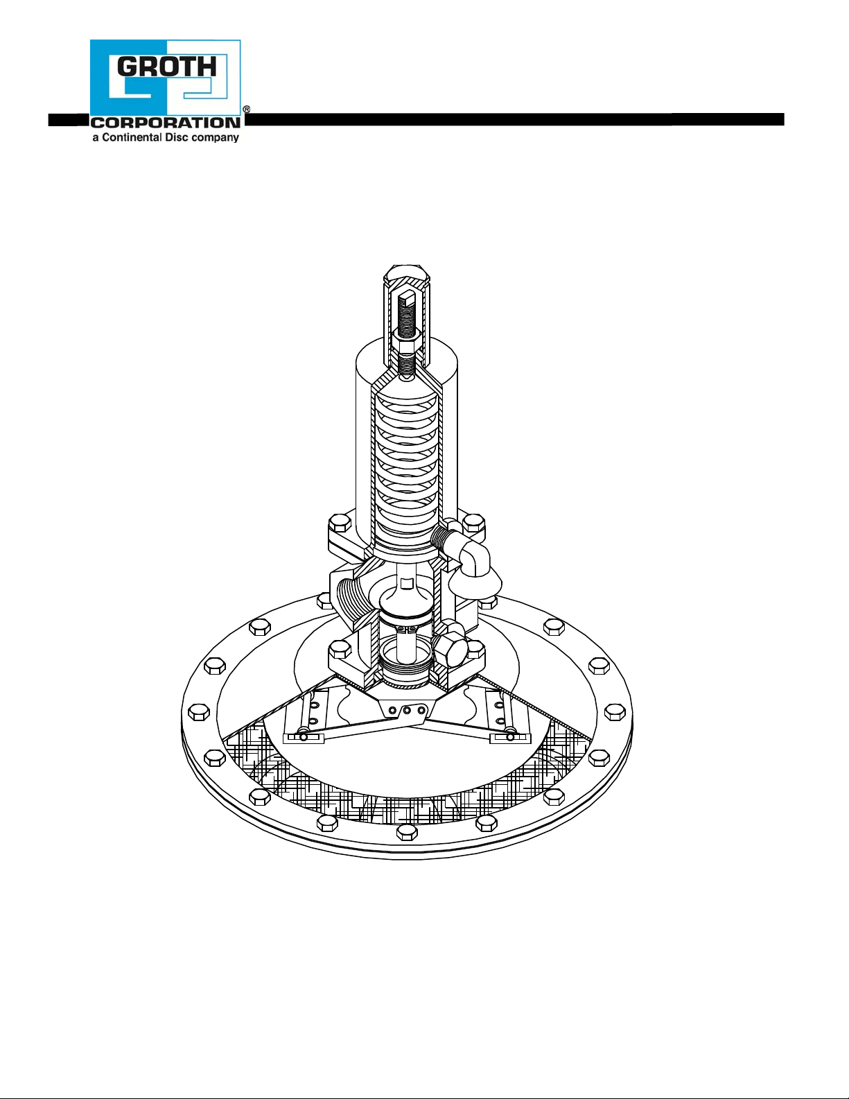
FIGURE 12: CROSS SECTIONAL ASSEMBLY
15
Page 17

MODEL 3011L, 3011H, 3041L AND 3041H
BILL OF MATERIAL
STANDARD MATERIALS OF
ITEM DESCRIPTION
1 BODY CF-8M (316 SS)
2 SPRING CHAMBER CF-8M (316 SS)
3 CAP, SPRING CHAMBER 316 SS
4 ACTUATOR HOUSING UPPER 316 SS
5 ACTUATOR HOUSING LOWER 316 SS
6 PISTON 316 SS
7 O-RING RETAINER 316 SS
8 RETAINER, DIAPHRAGM 316 SS
9 ADAPTER, BONNET 316 SS
10 SPRING BUTTON 316 SS
11 ADJUSTMENT SCREW 304 SS
12 ORIFICE SELECTOR SLEEVE 316 SS
13 SCREW, ORIFICE LOCK 316 SS
14 GUIDE- PISTON RING 316 SS
15 ACTUATOR SUPPORT PLATE 316 SS
16 BRACKET SUPPORT PLATE 316 SS
17 ARM, ACTUATOR INNER 316 SS
18 ARM, ACTUATOR OUTER 316 SS
19 BRACKET, ACTUATOR HOUSING 316 SS
20 ROLLER, ACTUATOR NYLON
21 ROLLER, ACTUATOR NYLON
22 SPACER, ROLLER TYGON
23 PIN, ACTUATOR 316 SS
24 VENT ZINC PLATED STEEL
25 RIVET 316 SS
26 NAMEPLATE 316 SS
27 NUT, HEX JAM SS
28 BOLT, HEX SS
29 WASHER, LOCK SS
30 BOLT, BUTTON HEAD CAPSCREW SS
(1/2" Models Only)
31 BOLT, HEX SS
32 WASHER, LOCK SS
33 NUT, HEX SS
34 SPRING 316 SS
35 *
36 *
37 *
38 RING, RETAINING SS
39 SPACER, BRACKET ACT. HOUSING 316 SS
(1/2" 3011H Model Only)
40 *
41 *
42 *
43 CAPSCREW, SOCKET HEAD 316 SS
(1/2" Models Only)
44 NIPPLE, PIPE (OPTIONAL)
45 FLANGE, RF (OPTIONAL) 316 SS
46 HEX BOLT (1" Models Only) 316 SS
47 STOP LIFT (1" Models Only) 316 SS
48 ** CONNECTOR FEMALE 316 SS
49 ** 45º MALE ELBOW 316 SS
* SPARE PARTS
** 1/2" 3011L/3041L and 1" 3011H/3041H
GASKET, ACTUATOR (1)
DIAPHRAGM, PISTON (2)
O-RING, PISTON (2)
O-RING, GUIDE RING (2)
O-RING, LOCKING SCREW (2)
DIAPHRAGM, ACTUATOR (1)
(1) ELASTOMERS ALSO AVAILABLE IN EPR, BUNA-N & FFKM.
CONSTRUCTION
FEP
FKM
FKM
FKM
FKM
FEP
16
Page 18

17
Page 19

18
Page 20

19
Page 21

20
Page 22

The nameplate on the Groth Model 3011L and 3011H Tank Blanketing Regulator contains the model number, serial number, set
pressure & range and supply pressure. The model number contains additi onal information about material of construction, capacity
and options. The following chart will assist in relating the model number to the specifications of your regulator:
HOW TO ORDER
MODEL # INLET MATERIAL SOFT ORIFICE SPRING OPTIONS
OUTLET GOODS POSITION RANGE
A = 1" 150# ANSI RF FLANGE 5 = 316 SS 1 = 100% SELECT FROM 0 = NONE
3011L E = 1/2" 150# ANSI RF FLANGE 2 = 75% SPRING Z = SPECIAL
3011H N = 1" NPT 3 = 50% SELECTION OPTIONS
3041L O = 1/2" NPT B = BUNA-N 4 = 25% TABLE
3041H C = DN25 PN 10/16 DIN RF FLANGE E = EPDM 5 = 20%* (PAGE 6)
3011HPF = DN15 PN 10/16 DIN RF FLANGE
V = FKM 6 = 15%*
3041HP
Q = 1/2" QUICK COUPLINGS C = FFKM 8 = 5%*
* NOT OPTIONAL FOR 1/2” SIZE
S = 1/2" SANITARY CONNECTIONS Z = SPECIAL 7 = 10%*
EXAMPLE 3 0 1 1 H - N - 5 - V - 1 - 2 - 0
Indicates a model 3011H regulator 1" size with 1" NPT body connections, 316 SS construction, FKM
elastomers, full capacity orifice, set pressure range from 1.0" WC to 1.5" WC and no special options.
A "Z" in the model number indicates a non-standard material or feature. Review your purchase specifications or consult Groth
Corporation for more details.
PRODUCT LIMITED WARRANTY
Only Groth’s Product Limited Warranty terms apply to purchase orders accepted by Groth Corporation.
A. Seller warrants that products that are manufactured by Seller are manufact ured in accordance with publ ished specifications
and free from defects in materials and/or workmanship for a period of ( 12) twelve mont hs. Seller, at it s option, will repair or
replace any products returned intact to the factory, transportation charges prepaid, which Seller, upon inspection,
determines to be defective in material and/or workmanship. The foregoing shall constitute the sole remedy for any breach of
Seller’s warranty.
B. THERE ARE NO UNDERSTANDINGS, AGREEMENTS, REPRESENTATIONS, OR WARRANTIES, EXPRESS OR
IMPLIED (INCLUDING MERCHANTABILITY OR FITNESS FOR A PARTICULAR PURPOSE REGARDING PRODUCTS)
UNLESS SPECIFIED IN THE SALES CONTRACT. THIS CONTRACT STATES THE ENTIRE OBLIGATION OF SELLER.
Seller makes no warranties, either express or implied, except as provided herein, including without limitation thereof,
warranties as to marketability, merchantability, for a particular purpose or use, or against infringement of any patent of
products. In no event shall Seller be liable for any direct, incidental or consequential damages of any nature, or losses or
expenses resulting from any defective new product or the use of any such product, including any d amages for loss of time,
inconvenience, or loss of use of any such product.
C.The original Manufacturer shall be solely responsibl e for the design, development, supply, production, and performance of
its products hereunder, and the protection of its trade name or names, if any. It assumes no respo nsibility, for products
modified or changed by its agent or customer, or any othe r third party. Any such modifications or ch anges to products sold
by Seller hereunder shall make the product limited warranty null and void.
D.Groth assumes no responsibility for products modified or changed by Customer or any other third party. Any such
modifications or changes to products sold by Groth hereunder sh all make the product limited warranty null and vo id. Groth
shall be under no obligation to manufacture, sell or supply, or to continue to manufacture, sell, or supply any of the products.
21
 Loading...