

Page 1
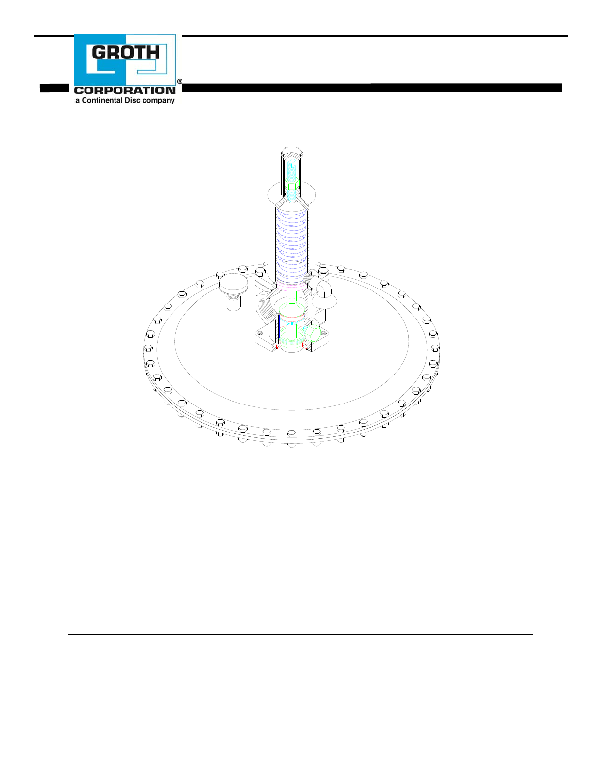
Installation, Operation and Maintenance Manual for
Blanket Gas Regulator
Series 3000
ISO 9001
Groth Corporation 1993
IOM 3000.0
JULY 1993
IOM 3000.0
REV. A 12541
Page 2

TABLE OF CONTENTS
SECTION DESCRIPTION PAGE NO.
A MAIN SECTION
INTRODUCTION
GENERAL
INFORMATION
SAFETY
INSTALLATION
OPERATION &
MAINTENANCE
DRAWINGS & BILL
OF MATERIAL
B LIST OF FIGURES*
No.
1
2
3
4
5
6
7
8
9
10
11
12
13
14
15
C LIST OF TABLES
No.
1
2
3
4
5
6
7
8
9
Regulator Design, Function & Operation
Regulator Function - Flowing/Shut-off Condition
General Instructions
Inspection & Installation
Operation: Pressure Setting
Operation: Flow Capacity Setting
Blanketing the Tank
Recommended Spare Parts
Troubleshooting Guide
Preventive Maintenance & Disassembly
Assembly
Recommended Testing & Setting Procedure
Exploded View - Drawing
Bill of Material
Cross-Sectional - Drawing
Model Identification & Product Limited Warranty
DESCRIPTION
Tank Installation - Safety Equipment
Regulator Function - Flowing Condition
Regulator Function - Shut-off Condition
Blanketing Regulator Installation
Orifice Sleeve Orientation
Spring Bonnet Assembly
Piston/Body Assembly
Piston Assembly - "Exploded"
Orifice Sleeve Orientation
Orifice Sleeve Orientation
Piston Assembly - "Exploded"
Piston/Body/ Diaphragm Assembly
Spring Bonnet Assembly
Blanketing Regulator - "Exploded" Assembly
Blanketing Regulator - Cross-Sectional Assembly
DESCRIPTION
3000 Series Regulator Specifications
Flow Capacity
Model 3000 Spring Table
Model 3010 Spring Table
Model 3020 Spring Table
Orifice Selection
Recommended Spare Parts
Recommended Bolt Torque
Bill of Material - 3000 Series Regulator
1
2
3
4
5
6
7
8
8
9
10 - 11
12 - 13
14
15
16
17
18
1
3
3
5
7
10
10
11
11
12
12
13
13
15
17
2
2
6
6
6
7
8
13
16
IOM 3000.0
REV. A 12541
Page 3
*Note: Some Figures are duplicated for the convenience of the reader
P
INTRODUCTION
The gas blanketing regulator is one of the principal
components typically installed on a storage tank to
protect the tank and its contents. It is a precision
regulator that is capable of maintaining a very low
gas pressure (1/2" WC minimum) in the tank by
controlling the flow of a high pressure (200 PSI
maximum) blanketing gas. It maintains a positive
tank pressure when fluid is pumped out or as fluid
temperature decreases.
Typically nitrogen or another compatible gas is used
to displace the tank product vapors. This reduces
product evaporation and prevents atmospheric
contaminants, including moisture, from entering the
tank, minimizing internal tank corrosion and product
contamination. The use of inert blanketing gas
minimizes air pollution due to leakage or emergency
venting.
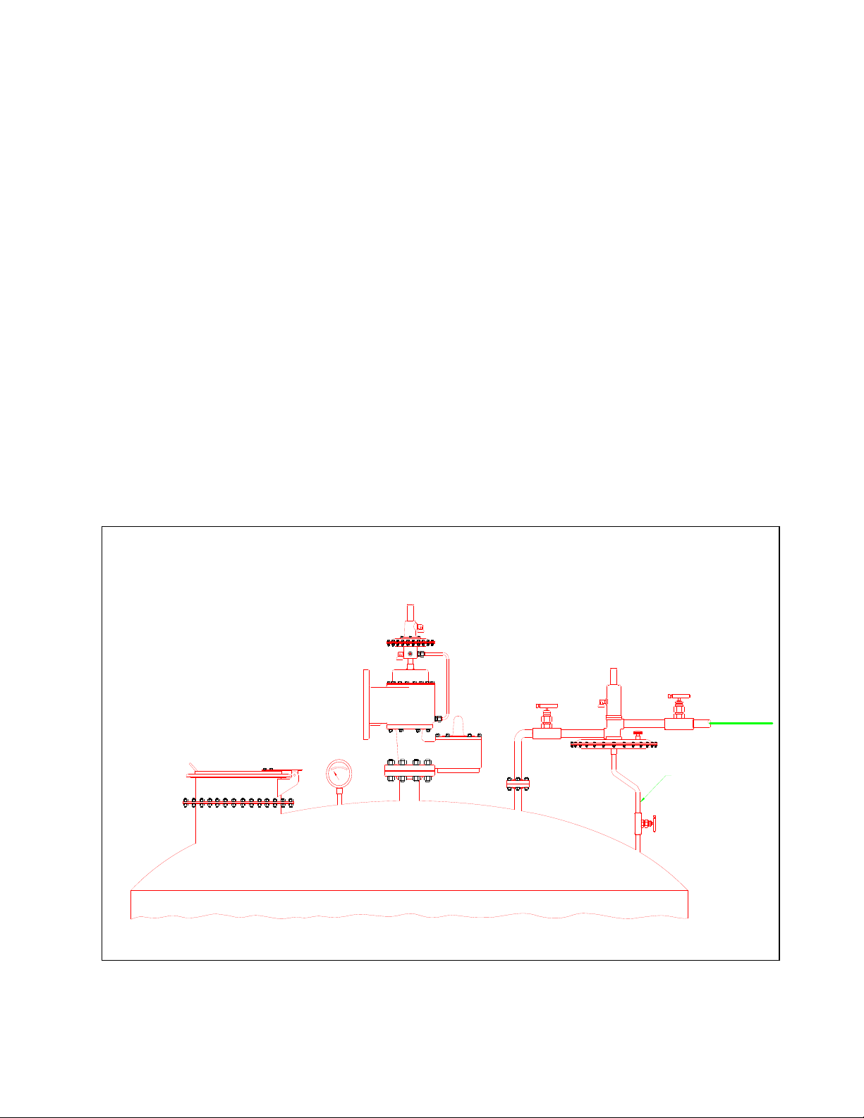
Figure 1: Tank Installation - Safety Equipment
In addition to the blanketing regulator, a tank must be
protected from structural damage by pressure and
vacuum relief valves. A typical tank installation is
shown in Figure 1 which includes the regulator, a
pressure vacuum relief valve and an emergency
pressure relief valve. Groth Corporation
manufacturers all of these devices.
The regulator must be carefully maintained by a
knowledgeable valve technician. It should only be
assembled under clean conditions, preferably in a
shop environment. Carefully read and understand
this manual before attempting to adjust set pressure
or flow capacity, or repair the regulator. Groth
Corporation offers repair services for all products
manufactured by the Tank Protection Division.
RESSURE/VACUUM
RELIEF VALVE
GROTH MODEL 1420
GAS BLANKET REGULATOR
GROTH MODEL 3000
BLANKET
GAS
EMERGENCY RELIEF VALVE
GROTH MODEL 2400
GAUGE
SENSE LINE
SUPPLY
IOM 3000.0
REV. A 12541
Page 4
REGULATOR DESIGN, FUNCTION &
OPERATION
The Groth Model 3000 Regulator is a high capacity
spring operated, diaphragm type, balanced piston
regulator design for tank blanketing applications.
The regulator controls the flow of blanketing gas to
the vapor space in the storage tank. When the
internal pressure of the tank is at or above set
pressure, the diaphragm force exceeds the spring
force and the regulator is shut off bubble tight.
When the tank pressure falls below the set point, the
spring force opens the regulator and blanket gas
flows into the tank (See Figures 2 and 3).
The regulator must be sized to provide sufficient
blanket gas to prevent the loss of tank pressure due to
liquid discharge or decreased ambient temperature.
Table 2 lists the maximum flow capacity of the
regulator for various blanketing gases. Actual
system flow will depend on supply system piping,
tank connection piping and position of the internal
orifice sleeve. Set pressure is the pressure at which
the regulator begins flowing when tank pressure is
decreasing and stops flowing when tank pressure is
increasing.
This manual is intended to provide recommended
procedures and practices for installation, operation,
and maintenance of the Groth Series 3000 Regulator.
Any standard procedures and practices developed in
a specific plant or process should supersede this
manual. Although this manual cannot cover all
possible contingencies, following these guidelines
should provide safe regulator performance.
For information not contained in this manual, please
contact:
Groth Corporation
Groth Products Group
P. O. Box 15293
Houston, TX. 77220
713-675-6151 (phone)
713-675-6739 (fax)
Note that throughout this manual, the item numbering
is listed in [ ] after the part description. Refer to the
exploded assembly drawing on page 15 and the parts
list on page 16.
TABLE 1
REGULATOR SPECIFICATIONS
3000 3010 3020
Flow
Coefficient
(CV)
Inlet/Outlet 1" NPT (F)
Supply Pressure 200 PSI
Tank Pressure 2" WC to
Max. Tank
MAWP
12.5 12.5 12.5
or
1"150# RF
Flange
2.0 PSI
25 PSI 10 " WC 150 PSI
1" NPT (F)
or
1" 150# RF
Flange
200 PSI
1/2" WC to
2" WC
1" NPT (F)
or
1" 150# RF
Flange
200 PSI
1 PSI to
10 PSI
TABLE 2
FLOW CAPACITY *
3000 SERIES REGULATOR SCFH
Supply
Pressure
PSI
5
10
15
20
30
40
50
60
80
100
120
140
160
180
200
Nitrogen Natural
Gas
0.6 G
5700
8700
11300
13800
18600
23200
27700
32100
40700
49300
57900
66500
75100
83700
92300
5800
8800
11500
14000
18900
23600
28200
32600
41300
50100
58800
67500
76300
85000
93700
Air
7400
11300
14600
17900
24000
30000
35800
41500
52600
63700
74800
85900
97000
108100
119200
Internal orifice sleeve installed in 100% flow capacity
*
position.
1
Page 5

P
R
Figure 2: Regulator Function - Flowing Condition
VENT
INLET
HIGH PRESSURE
OUTLET
HIGH PRESSURE
BLANKETING GAS
BLANKETING GAS
VENT
SENSE PORT
LOW PRESSURE
PROCESS VAPOR
Figure 3: Regulator Function - Shut-off Condition
INLET
HIGH PRESSURE
OUTLET
LOW PRESSURE
PROCESS VAPOR
SENSE PORT
LOW PRESSURE
ROCESS VAPO
BLANKETING GAS
VENT
2
Page 6

SAFETY
GENERAL INSTRUCTIONS
This section is intended as an overview of safety
guidelines that should be followed during the
installation, operation and maintenance of Groth
Series 3000 Gas Blanketing Regulator. To
understand the context of these warnings and
instructions, read and understand this complete
manual.
The gas blanketing regulator is one of the principal
protection devices typically installed on a product
storage tank. It is a precision regulator that is
designed to maintain a positive pressure on the tank.
This will prevent product loss or contamination from
atmospheric air when pumping liquid out or when the
stored fluid cools.
WARNING
1. In the event of an actuator or body diaphragm
failure, the regulator will fail in the OPEN
position. Gas flow will NOT be shut off.
Operating and emergency pressure relief valves
must be sized to flow regulator capacity in
addition to normal and emergency venting
requirements.
2. Gas Blanket Regulator flow capacity is based on
tests conducted with five feet of 1" SCH. 40
discharge piping. Consult factory for capacity
data if regulator is to be installed with longer
pipe or numerous fittings or va lves between the
regulator and the tank it is blanketing.
3. The regulator is normally factory set at the
desired set pressure and orifice restriction.
These settings and spring range are stamped on
the nameplate. DO NOT attempt to readjust the
set pressure beyond the limits specified in Tables
3, 4 and 5.
4. The regulator is to be connected to the tank or
vessel with a minimum 0.300" ID tubing sense
line. This line must be kept open and
unobstructed to ensure that the regulator
"senses" the actual tank pressure. For some
applications, a nitrogen purge may be required
to ensure that this line remains open. Consult
factory for recommendations.
5. DO NOT attempt to remove the regulator from
the line or perform field repairs in line without
first isolating the regulator from both the tank
and the supply gas line. Bleed all pressure
before removing the spring bonnet or the flow
orifice locking screw, or opening up the actuator
cases.
6. Note the orifice sleeve position when
disassembling the regulator. It was factory set
according to the flow requirements listed on the
order and must be re-installed in the same
position to ensure the correct flow.
7. The regulator body and actuator case are
exposed to process vapors. Observe all safety
precaution as specified on the Material Safety
Data Sheet for the products that are in the tank.
8. The vents on the spring bonnet and upper case
must both be clean and open to the atmosphere
and should be inspected periodically.
3
Page 7
INSPECTION AND INSTALLATION
B
The regulator is packaged and supported to prevent
damage or contamination in shipping. It should be
similarly protected during subsequent handling and
storage. Always keep all ports plugged to prevent
intrusion of foreign materials. Before installation,
inspect the unit visually. If there are indications of
physical damage or internal contamination, the
regulator must be disassembled, cleaned and
inspected before installation. If factory set, the
spring adjustment cap and the orifice selector locking
screw must be secure. Report any shipping damage
to your carrier.
The regulator inlet and outlet connections are 1" NPT
(F) or 1" 150# RF ANSI flange. The regulator must
be installed level, the direction of the flow is marked
on the body. It is to be installed in accordance with
accepted piping practices. Full bore block valves
should be installed upstream and downstream of the
regulator and in the sense line to allow it to be
removed from the system for maintenance.
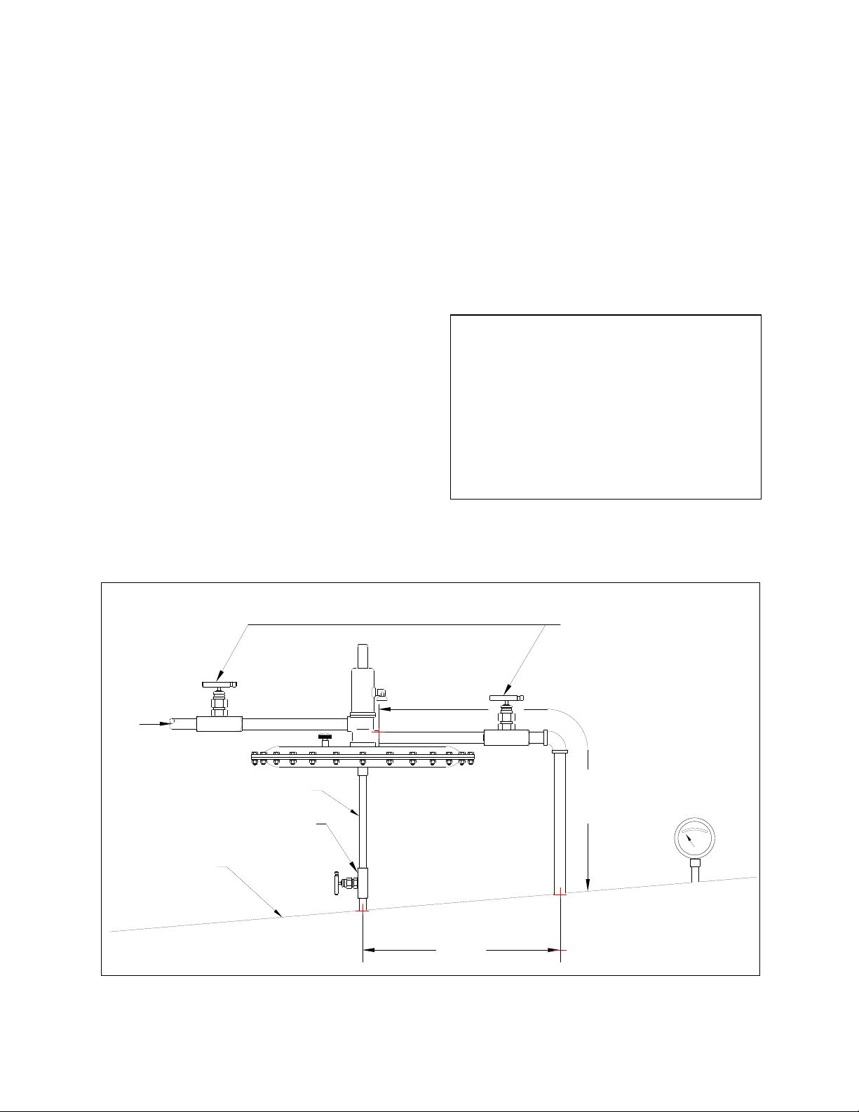
Figure 4: Blanketing Regulator Installation
The regulator discharge line must be as short as
possible to obtain the rated gas flow rate. It is not
recommended to exceed a 5' length of 1" SCH 40
pipe. Consult with the factory for piping
recommendations if it is necessary to install the
regulator a greater distance from the tank. The
supply line must be capable of providing the rated
flow at the minimum supply pressure. The sense line
should be minimum 300" ID tubing and is to be
connected to the tank at least 12" from the regulator
discharge line (See. Figure 4).
WARNING
Regulator flow capacity listed in Table 2 is based on
tests with 5' of 1" SCH. 40 discharge pipe and a 2"
supply hose reduced to 1" pipe at regulator supply
port. Depending on discharge line size, length and
number of fittings, regulator flow capacity may be
less than published curves. Supply and discharge
piping should be designed to minimize losses at
desired flow condition. Consult factory for nonstandard installation regarding flow capacity.
BLANKET
GAS
SUPPLY
BLOCK VALVE-1/2" MIN FULL BORE
TANK ROOF
(3)
SENSE LINE
(1)
12" MIN
(2)
LOCK VALVE-1" MIN FULL BORE
DISCHARGE
PIPING
5' MAX
LENGTH
TANK
PRESSURE
GAUGE
4
Page 8

OPERATION
PRESSURE SETTING
The regulator may be set at the factory or on the tank
or vessel when initially introducing blanketing gas.
A pressure gauge (or manometer) is required to show
the tank pressure.
Set pressure is adjusted by removing the valve cap
[1] and rotating the adjusting screw [2]. Back off the
jam nut [3] and turn the screw clockwise (tighten) to
increase set pressure. The Model 3000 Regulator
covers a range of set pressures from 2" WC to 2.0
PSI, using (7) different springs.
TABLE 3
SPRING TABLE
MODEL 3000
TANK BLANKETING REGULATOR
MEDIUM PRESSURE RANGE
SET PRESSURE RANGE: 2" WC - 2.0 PSIG
Spring
Range
1
2
3
4
5
6
7
Min.
Setting
11.0"
18.6"
2.0"
WC
3.4"
WC
6.3"
WC
WC
WC
1.00
PSI
1.38
PSI
Max.
Setting
10.9"
18.5"
27.7"
1.37 PSI 84209006
Spring
P/N
3.4"
84209001
WC
(Yellow) 83602015 83601005 4 PSI
6.3"
84209002
WC
(Green) 83602015 83601005 4 PSI
84209003
WC
WC
WC
2.0
PSI
(Pink)
84209004
(Blue)
84209005
(White)
(Gray)
84209007
(Black)
Support
Plate
83602015
83602025
83602025 83601025
83602025 83601025
83602025 83601035
Back-up
Plate
83601005 4 PSI
83601025
Tank
MAWP
25
PSI
25
PSI
25
PSI
25
PSI
WARNING
The recommended set pressure range of the regulator
spring is stamped on the nameplate. Never adjust a
spring for a set pressure above its upper design limit
as specified in Tables 3, 4 and 5. Exceeding the spring
rang may compress the spring to its solid height. If
this happens the regulator may not close and the tank
could be over-pressured if the relief valve capacity is
less than supply gas flow rate.
The model 3010 is required for set pressures from
1/2" WC to 2" WC, and model 3020 from 2.0 PSI to
10.0 PSI. In some cases, different actuator
components are also required, either to reduce the
weight for low settings or to withstand the forces due
to higher pressure. (See. Tables 3, 4 and 5).
The set pressure range with the original spring is
stamped on the valve nameplate. The regulator will
not function properly if the setting is not within this
range. If higher or lower settings are required, the
necessary components can be obtained from Groth
Corporation. They must be installed according to
instruction in the maintenance section of this manual.
Tables 3, 4 and 5 show standard set pressure ranges.
TABLE 4
SPRING TABLE
MODEL 3010
TANK BLANKETING REGULATOR
LOW PRESSURE RANGE
SET PRESSURE RANGE: 0.5" WC - 2.0" WC
Spring
Range
1
2
3
Min.
Settin
g
0.5"
WC
0.7"
WC
1.1"
WC
Max.
Setting
0.6"
WC
1.0"
WC
2.0"
WC
Spring
P/N
84209008
(Red)
84209001
(Yellow)
84209002
(Green)
Support
Plate
83602035 83601005
83602035 83601005
83602005 83601015
Back-up
Plate
Tank
MAWP
10"
WC
10"
WC
10"
WC
TABLE 5
SPRING TABLE
MODEL 3020
TANK BLANKETING REGULATOR
HIGH PRESSURE RANGE
SET PRESSURE RANGE: 1.0 - 10.0 PSIG
Spring
Range
1
2
3
4
Min.
Setting
1.0
PSI
1.81
PSI
3.08
PSI
5.22
PSI
Max.
Setting
1.80
PSI
3.07
PSI
5.21
PSI
10.0 PSI
Spring
P/N
84209002
(Green)
84209003
(Pink)
84209004
(Blue)
84209005
(White)
Support
Plate
84829005 N/A
84829005 N/A
84829005 N/A
84829005 N/A
Back-up
Plate
Tank
MAWP
150
PSI
150
PSI
150
PSI
150
PSI
5
Page 9

FLOW CAPACITY SETTING
Unless otherwise specified, the orifice selector sleeve
[34] is factory set at the 100% full open position. If
reduced capacity is specified on an order, the sleeve
is set at the appropriate restriction. Actual capacity at
any other position can be calculated by multiplying
the capacity value from Table 2 for a specific
pressure by the decimal fraction from Table 6.
Flow capacity can be adjusted by rotating the orifice
sleeve (See Warning). It has a series of indexing
holes, four of which are marked with the numbers 12-3-4 (See Figure 5). Two unmarked holes are used
to assist when rotating the sleeve. Adjustment can be
made by loosening and backing the lockdown screw
completely out of the body. The sleeve position can
then be viewed and the sleeve rotated by inserting a
small diameter wire into the holes.
Figure 5: Orifice Sleeve Orientation
34
3
2
2
36 35
WARNING
The adjustable orifice is located in a pressure
containing chamber. Close the supply valve and
release all pressure before making adjustments.
When replacing the locking screw, grease the O-Ring
[35] and slip it over the screw threads. Thread the
screw [36] into the body, finger tight, until the point
enters the sleeve and the head seats onto the O-Ring.
Then wrench tighten the head firmly against the
body, compressing the O-Ring.
Sleeve position and valve capacity are shown in
Tables 2 and 6. These tables are based on the supply
pressure at the regulator inlet and piping as
recommended in the installation section.
WARNING
The regulator orifice sleeve is factory set at the
specified flow capacity. When repairing a
regulator, note the position of the indexing holes at
disassembly. The sleeve must be re-assembled in
the same position to ensure the proper flow
capacity. NEVER adjust the orifice sleeve position
without written instructions from your plant
operations group.
TABLE 6
ORIFICE CAPACITY
Orifice Sleeve
Position
1
2
3
4
Flow
Multiplier
1.0
0.75
0.50
0.25
6
Page 10

BLANKETING THE TANK
Before installing a new or replacement regulator, the
tank pressure must be below the desired set pressure
so the regulator setting can be verified. Sequentially
open the block valves in the following order: (1)
Sense Line, (2) Regulator Discharge Line and (3)
Regulator Supply (See Figure. 4).
If the regulator was set at the factory, blanket gas will
begin to flow immediately. The tank pressure must
be monitored closely to verify that the gas flow shuts
off within the specified limit above set pressure.
If the regulator was not set at the factory, make sure
that the adjusting screw [2] is backed out as far as
possible (no spring compression). When the blanket
gas supply valve is turned on, there will be no flow,
unless the tank pressure is very low. Now slowly
turn the adjusting screw to increase tank pressure and
the gas will begin to flow. The tank pressure can be
increased as gradually as desired until the correct
pressure setting is attained. When tank pressure is
reached, back out adjusting screw, if necessary, until
gas flow stops.
RECOMMENDED SPARE PARTS
When ordering spare parts, include model and serial number of regulator, pressure setting, and required material for
soft goods.
When adjusting the regulator on the tank, always be
sure that the sense line is open and unobstructed.
Monitor the tank pressure accurately.
In the event of actuator diaphragm [14] or piston
diaphragm [21] failure, the regulator will fail in the
OPEN position. Under this condition gas flow will
NOT be shut off by the regulator. The tank pressure
relief valve(s) must be sized to relieve the condition
of full regulator capacity, pump in rate; and thermal
expansion due to temperature rise. In the event of
blanket supply gas failure, the regulator will NOT
protect the tank from collapse due to a vacuum
condition. The operating relief valve should include
a vacuum breaker set according to the tank's design
vacuum capacity.
WARNING
WARNING
TABLE 7
RECOMMENDED SPARE PARTS
ITEM DESCRIPTION QUANTITY
14 Diaphragm, Actuator 2
21 Diaphragm, Piston 4
25 O-Ring, Piston 2
22 O-Ring, Guide Ring 2
35 O-Ring, Locking Screw 2
6 Spring 1
11 Vent, Case 1
7 Vent, Bonnet 1
39 Gasket, Actuator 2
7
Page 11

PROBLEM
Gas flowing at tank
pressure above
specified set point.
Gas not flowing at
tank pressure below
specified set point.
Gas leaking from
upper vent or bonnet
flange.
Gas leaking from
lower body seal or
case vent.
Process vapor leaks
from case flange or
vent.
Tank pressure above
or below specified
operating range
during pump out or
pump in.
Tank pressure or
vacuum exceeds vent
settings during pump
out or pump in.
TROUBLESHOOTING GUIDE
INSPECTION
Flow indicator in
blanket gas line.
Flow indicator in
blanket gas line.
Soap bubble test
and joining
surface or
emission
indication near
vent.
Soap bubble test at
joining surface or
emission
indication near
vent.
Soap bubble test at
joining surface or
emission
indication near
vent.
Observe tank
pressure indicator
during pumping
operations.
Observe tank
pressure indicator
during pumping
operations.
SUGGESTED CORRECTIVE ACTION
Damaged seat, O-Ring or diaphragm or pressure
setting too high. If original pressure setting has
not been disturbed, remove regulator and repair.
Damaged spring or pressure setting too low. If
original pressure setting has not been disturbed,
remove regulator and repair.
Damaged upper piston diaphragm. Remove
regulator from tank and replace diaphragm.
Diaphragm installed incorrectly. Reinforcement
fabric must be opposite to pressure (see page
13).
Damaged lower piston diaphragm. Remove
regulator from tank and replace diaphragm.
Diaphragm installed incorrectly. Reinforcement
fabric must be opposite to pressure (see page
13).
Damaged actuator diaphragm or loose case bolts.
Tighten bolts or remove regulator from tank and
replace diaphragm.
Excess or insufficient blanket gas flow. Check
flow orifice orientation. Refer to Tables 2 & 6
for flow capacity data. Check gas supply
pressure. Remove and repair regulator if other
conditions are correct.
Pressure/vacuum relief vent not functioning
properly. Inspect and repair or replace as
necessary.
8
Page 12

Figure 6: Spring Bonnet Assembly
1
2
3
5
WARNING
Before removing the regulator from the tank for
service, block supply pressure and vent all trapped
pressure. Never attempt to remove the regulator
from the line if it is pressurized.
WARNING
Do NOT attempt to remove the spring chamber [4],
flow orifice locking screw [36], or any pipe
connections from the body [20], while the regulator
is pressurized.
PREVENTIVE MAINTENANCE
Periodically, while in service, examine the regulator
for leakage at bolted connection, adjusting screws,
etc. Test for blanket gas or process vapor emissions
from vent caps.
DISASSEMBLY
All service on the regulator may be performed with
the following common tools:
7/16" thru 1" box end wrenches
3/8" open end wrench*
3/16" Allen key
*Wrench must be 16" long for flanged units.
Thread a 1/2" pipe nipple into the sense port on the
lower diaphragm case [15]. Use a vise and clamp
onto the pipe nipple. This makes a good holding
4
6
28729
fixture and provides some degree of rotation while
working on the regulator.
WARNING
Diaphragm actuator case and regulator body are
exposed to the process vapor(s). Observe all
standard safety precautions as specified on Material
Safety Data Sheets for the product(s) that are in the
tank. These precautions apply both during removal
of the regulator from the tank and while repairing
it.
Remove the adjustment screw cap [1] and loosen the
jam nut [3]. Turn the adjustment screw [2]
counterclockwise to completely relax the spring [6].
Remove the cap screws [28] and the lock washers
[29]. Remove the spring bonnet [4]. Remove the
spring upper button [5], the spring [6], the lower
spring button [5] and then the bonnet adapter ring
[10]. Use a 3/8" open end wrench and insert it
through the inlet port to hold onto the piston [24] at
the wrench flats. Remove the upper piston pin [8]
while holding onto the piston. Be careful not to let
the piston rotate during removal of the upper piston
pin. The piston diaphragms [21] can easily be torn if
care is not taken.
Figure 7: Piston/Body Assembly
20
WRENCH
FLATS
9
8
21
24
Remove the upper diaphragm retainer [9] and the
upper piston diaphragm [21].
9
Page 13

Remove the hex nuts, lockwashers, and hex bolts
(items 18, 17, & 16 respectively). Remove the upper
diaphragm case assembly [12] straight up.
Loosen the vise and remove the lower diaphragm
case with the pipe nipple still intact. Turn the upper
diaphragm case assembly upside down and use a vise
to hold on to the body [20].
Insert the 3/8" open end wrench through the inlet port
and hold on to the piston at the wrench flats while
loosening the countersunk screw [37] (See Figure
12).
Figure 8: Piston Assembly - "Exploded"
24
25
31
Remove the lift stop ring [33] from the groove by
expanding the ring slightly; and slide it over the
piston with care. Do not overexpand the ring.
Remove the retaining ring [32] with retaining ring
pliers. Expand retaining ring just enough to slide
over the piston. Be careful not to scratch the piston
surface. Remove the O-Ring retainer [31] and the oring [25].
Figure 9: Orifice Sleeve Orientation
34
3
2
32
33
Remove the washer [38], the diaphragm [14], the
diaphragm support plate [13] and then the back-up
plate [19].
Use a 3/16" Allen hex key and remove the
countersunk screws [30]. Remove the upper
diaphragm case [12].
Lift the piston sub-assembly [24] straight up and
remove from the body for disassembly. Lay the
piston subassembly horizontally on a clean flat
surface. Hold the piston at the wrench flats and
remove the lower pin [26], the diaphragm retainer
[9], the diaphragm [21], the O-Ring [22] and then the
guide ring [23].
Remove the piston sub-assembly from the body.
2
36 35
Refer to "FLOW CAPACITY SETTING" and
warnings before disassembling lockdown screw [36]
from body. Loosen and screw the lock down screw
[36] completely out of the Body. Before removing
the orifice selector sleeve [34], make note of its
position by looking through the 1/2" lock down
screw port. There will be a number stenciled on the
sleeve indicating the position of the sleeve. Note this
number for re-assembly. Refer to Tables 2 & 6 to
determine flow capacity of the regulator at a specific
open position.
All components should be examined for damage or
wear. Replace all seals and diaphragms. Prior to
reassembly, make sure all components are clean and
free of contamination.
10
Page 14

ASSEMBLY
Before assembly note the following material and tool
requirements:
1. Diaphragms, O-Rings, gasket, vents and
spring as listed in Table 7:
Recommended Spare Parts on page 8.
2. Lubricants & Thread Sealants
A. Silicone Grease
Dow Corning No. 33
B. Anti-Galling Lubricant
Dow Corning G-N Metal
Assembly Spray
C. Thread Sealant
Loctite Threadlocker No. 222
D. Fluoropolymer tape
3. Assembly Tools
A. 7/16" - 1" box end wrenches
B. 3/8" open end wrench*
C. 3/16" Allen key
* Wrench must be 16" long for flanged units.
All screw threads and static O-Ring should be lightly
greased with silicone grease. Lubricate the piston
OD at both ends and the spring adjusting screw with
an anti-galling spray. If the greases listed above are
not compatible with the tank vapors, use equivalent
lubricants for that media. All pipe threads are to be
wrapped with Fluoropolymer tape or suitable pipe
thread sealant applied sparingly.
Before installing the orifice selector sleeve, read the
section entitled "FLOW CAPACITY SETTING" and
related warnings on page 7. Install the orifice
selector sleeve [34] into the regulator body. Observe
the sleeve position locking hole by looking in the
locking screw hole in the body. The hole in the
sleeve should be exactly centered in the screw hole.
If the holes do not line up exactly, invert the sleeve
and reinstall. The position indicating numbers will
also be seen through the screw hole.
These numbers indicate % open and flow capacity
according to Tables 2 and 6. Make sure that the
sleeve position is on the same number as when
disassembled, or on the number that provides the
specified flow requirements.
Figure 10: Orifice Sleeve Orientation
34
3
2
2
36 35
Grease the locking screw O-ring [35] and slip it over
the screw threads. Thread the locking screw [36]
into the body, finger tight, until the point enters the
sleeve and the head seats onto the O-ring. Then
wrench tighten the head firmly against the body,
compressing the O-ring.
Note: Damage to the sleeve will occur if force is
applied with the point of the locking screw.
Figure 11: Piston Assembly - "Exploded"
24
25
31
32
Assemble the piston sub-assembly according to
Figure 11. Install the O-Ring [25] from the top end
of the piston. Do not rotate the o-ring, but stretch it
just enough to clear the piston diameter. When
installing the retaining ring [31], snap ring [32] and
lift stop ring [33] expand the rings just enough to
33
11
Page 15

clear the piston without scratching the piston or
permanently deforming the rings.
Secure the body in a vise with the bottom surface
facing upward and the inlet port accessible (See
Figure 12). Spray the piston sub-assembly with an
anti-galling lubricant and insert it and the guide ring
[23], into the body. Install the body O-Ring [22].
Set the piston diaphragm into the upper actuator
housing with reinforcing fabric away from the piston
(opposite to the supply pressure). Refer to Figure 12.
Attach the upper diaphragm case [12] to the body,
being sure that the piston wrench flats are accessible
through the inlet port before tightening the
countersunk screws [30].
Figure 12: Piston/Body/Diaphragm
38
37
13
26
34
33
32
31
21
19
21
22
23
24
25
WRENCH
FLATS
Attach the sense diaphragm [14], support plate [13],
back-up plate [19] and washer [38] (See Figure 15).
Clean thread surfaces thoroughly and apply Loctite
Threadlocker No. 222 to countersunk screw [37].
Align diaphragm and case holes and hold piston with
a 3/8" wrench through inlet port while tightening the
countersunk screw [37].
Attach the gasket [39] and lower diaphragm case [15]
with hex bolts, lockwashers and nuts [16, 17, & 18].
TABLE 8
RECOMMENDED BOLT TORQUE
[FT. - LB.]
Screw Size 1/4" 5/16" 3/8" 7/16" 1/2"
Torque
6
11 20
32
44
Clean all surfaces before assembly and tighten bolts
uniformly; refer to Table 8 for recommended torque.
Reposition the assembly in the vise. Install the upper
piston diaphragm [21], retainer [9] and pin [8]. Hold
piston with 3/8" wrench through inlet port while
tightening pin. Install the bonnet adapter ring [10],
spring [6], spring buttons [5] and spring bonnet [4].
Attach bonnet to body with hex bolts [28] and
lockwashers [29]. Tighten bolts uniformly; refer to
Table 8 for recommended torque.
Figure 13: Spring Bonnet Assembly
1
2
3
5
4
6
28729
Thread set pressure adjusting screw [2] into bonnet
until it engages the upper spring button. Tighten lock
nut [3] and replace cap [1].
Note: See Recommended Testing and Setting
Procedure.
WARNING
Replace bonnet vent [7] or case vent [11] if
damaged or restricted. A plugged case vent could
prevent the regulator from closing. This could
cause an over-pressure condition in the tank. A
plugged bonnet vent would prevent the release of
supply pressure from the bonnet. This could cause
personal injury when disassembling.
12
Page 16

RECOMMENDED TESTING AND SETTING PROCEDURE
1.0) Equipment
1.1) A high pressure air (or inert gas) supply
system capable of maintaining supply pressure
at 0-200 PSI. Flow may be controlled by a
reducing regulator or valve.
1.2) A low pressure air (gas) supply system
capable of maintaining sense pressure at 1/2"
WC to 10 PSI. Pressure may be controlled by
a regulator or needle valve and a small
accumulator. If a needle valve is used, it will
require frequent adjustment because the
regulator consumes a significant volume of air
when operating.
1.3) A means of indicating or measuring air flow
with a capacity of approximately 30 SCFH.
1.4) A means of soap bubble shell testing the
assembly.
2.0) Test procedure and Acceptance Criteria.
2.1) Connect the high pressure air supply to the
regulator inlet port.
2.2) Connect the low pressure air supply to the
regulator sense port.
2.3) Connect a reduced size manual shut-off valve
to the outlet port.
2.4) Connect a small diameter hose or plastic tube
to the inlet of the flow indicator o r flow meter.
Use a hand held port cover to attach the flow
meter to the regulator outlet port. Never
connect the flow meter rigidly to the regulator
unless the flow meter is rated for full air
supply pressure.
2.5) Connect a small diameter hose or plastic tube
to the outlet of the flow indicating device so
the end may be immersed in a container of
water.
2.6) Close the outlet valve and set the supply air
pressure to the maximum available, but not
greater than 300 PSI. Soap bubble test the
entire assembly at this pressure. Open the
outlet valve and reduce the supply until a
minimum audible flow is observed.
2.7) Adjust the sense pressure to the specified
regulator set pressure. Adjust the regulator
screw to shut off (no audible flow). Now
increase the sense pressure to 2 times the
specified set pressure or 1.5 times the
specified tank MAWP, whichever is greater.
Soap bubble test the actuator housing.
2.8) Increase the supply pressure to the specified
system pressure (100 PSI if not specified).
2.9) Slowly decrease the sense pressure and adjust
the regulator screw until the air flow is 5-20
SCFH at the specified setting. Lock the
adjusting screw at this setting.
2.10) While immersing the outlet tube in water,
increase the sense pressure until the regulator
is bubble tight. If this pressure exceeds 15%
or 2" WC greater than the set pressure,
examine the seat and O-Ring. Do not adjust
the regulator screw to improve bubble
tightness.
2.11) Remove the bonnet vent. Shut off the supply
pressure. Slowly decrease the sense pressure
to zero, while observing the stroke of the
piston thru the bonnet vent port. The stroke
must be 0.18" minimum. Replace the bonnet
vent.
3.0) Test report data.
3.1) The following data should be recorded for
future reference:
Model, Tag & Serial numbers
Test media
Body & Actuator shell test pressure
Supply pressure
Set pressure
Bubble tight pressure
13
Page 17

Figure 14: Blanketing Regulator - "Exploded" Assembly
1
3
2
4
28
29
7
5
6
5
10
8
9
21
23
22
21
9
26
16
11
12
19
30
24
25
31
32
33
PISTON
SUB-ASSY
BODY & SPRING
BONNET ASSY
20
35
36
34
13
14
38
37
39
15
17
18
ACTUATOR & PISTON ASSY
14
Page 18

TABLE 9
BILL OF MATERIAL
3000 SERIES BLANKET GAS REGULATOR
MATERIALS OF CONSTRUCTION
ITEM QTY DESCRIPTION CARBON
1
2
3
4
5
6
7
8
9
10
11
12
13
14
15
16
17
18
19
20
21
22
23
24
25
26
27
28
29
30
31
32
33
34
35
36
37
38
39
1
1
1
1
2
1
1
1
2
1
1
1
1
1
1
36
36
36
1
1
2
1
1
1
1
1
1
4
4
4
1
1
1
1
1
1
1
1
1
Cap, Adjustment Screw
Screw, Pressure Adjustment
Nut, Hex
Bonnet, Spring
Button , Spring
Spring
Vent, Bonnet
Pin, Upper Piston
Retainer, Diaphragm
Adapter, Bonnet
Vent, Case
Case, Upper Actuator
Plate, Diaphragm Support
Diaphragm, Actuator
Case, Lower Actuator
Bolt, Hex
Washer, Lock
Nut, Hex
Plate, Back-Up
Body
Diaphragm, Piston
O-Ring, Guide Ring
Ring, Guide - Piston
Piston
O-Ring, Piston Seat
Pin, Lower Piston
Nameplate
Bolt, Hex
Washer, Lock
Screw, Flathead
Retainer, O-Ring Piston Seat
Retaining Ring
Stop, Lift
Sleeve, Orifice Selector
O-Ring, Lockdown Screw
Screw, Locking - Flow Orifice
Screw, Flathead
Washer, Countersunk
Gasket, Actuator
STEEL
CS
SS
SS
CS
CS
316 SS
PVC or Alum
316 SS
316 SS
CS
PVC or Alum
CS
316 SS
Fluoropolymer
CS
SS
SS
SS
316 SS
316 SS
BUNA-N
BUNA-N
316 SS
316 SS
BUNA-N
316 SS
316 SS
SS
SS
SS
316 SS
SS
SS
316 SS
BUNA-N
316 SS
316 SS
SS
Non-Asbestos
STAINLESS
STEEL
SS
SS
SS
316 SS
316 SS
316 SS
PVC or Alum
316 SS
316 SS
316 SS
PVC or Alum
316 SS
316 SS
Fluoropolymer
316 SS
SS
SS
SS
316 SS
316 SS
FKM
FKM
316 SS
316 SS
FKM
316 SS
316 SS
SS
SS
SS
316 SS
SS
SS
316 SS
FKM
316 SS
316 SS
SS
Non-Asbestos
15
Page 19

Figure 15: Blanketing Regulator - Cross-Sectional Assembly
28 29
25
24
23
22
21
PISTON DETAIL
20
30
19
21
31
32
33
34
26
REF
27
TOP VIEW
SHOWS TRUE
ORIENTATION
1
2
3
4
5
6
7
8
9
10
11
INLET
OUTLET
18
17
16
38
35
36
37
SENSE
PORT
12
13
14
39
15
16
Page 20

The nameplate on the Groth Series 3000 Tank Blanketing Regulator contains the model number, serial number, set
pressure & range and supply pressure. The model number contains additional information about material of
construction, capacity and options. The following chart will assist in relating the model number to the
specifications of your regulator:
3000 N 5 V 1 O
Connections
N
F
Z
1" NPT (F)
1"150# RF
Special
Material
3
5
Z
Carbon Stl
316 SS
Special
Soft Goods
B
V
E
Z
Buna-N
FKM
EPDM
Special
Orifice
1
2
3
4
100%
75%
50%
25%
Options
0 Z None
Special
Model 3000 2" WC to 2 PSI Pressure Range
Model 3010 1/2" WC to 2" WC Pressure Range
Model 3020 1 PSI to 10 PSI Pressure Range
A "Z" in the model number indicates a non-standard material or feature. Review your purchase specifications or
consult Groth Corporation for more details.
EXAMPLE 3000 N 5 V 1 0 Indicates a 3000 Series Regulator with
Set Pressure Range from 2" WC - 2 PSI, 1"
NPT Body Connections, 316 SS Construction,
FKM Elastomers, Full Capacity Orifice and
No Special Requirements.
PRODUCT LIMITED WARRANTY
A. Seller warrants that products which are manufactured
by Seller, are manufactured in accordance with
published specifications and free from defects in
materials and/or workmanship for a period of (12)
twelve months. Seller, at its option, will repair or
replace any products returned intact to the factory,
transportation charges prepaid, which Seller, upon
inspection, shall determine to be defective in material
and/or workmanship. The foregoing shall constitute
the sole remedy for any breach of Seller's warranty.
B. THERE ARE NO UNDERSTANDINGS,
AGREEMENTS, REPRESENTATIONS, OR
WARRANTIES, EXPRESS OR IMPLIED,
(INCLUDING MERCHANTABILITY OR FITNESS
FOR A PARTICULAR PURPOSE REGARDING
PRODUCTS) UNLESS SPECIFIED IN THE SALES
CONTRACT. THIS CONTRACT STATES THE
ENTIRE OBLIGATION OF SELLER.
Seller makes no warranties, either express or implied,
except as provided herein, including without
limitation thereof, warranties as to marketability,
merchantability, for a particular purpose or use, or
against infringement of any patent of products. In no
event shall Seller be liable for any direct, incidental or
consequential damages of any nature, or losses or
expenses resulting from any defective new product or
the use of any such product, including any damages
for loss of time, inconvenience, or loss of use of any
such product.
C. The original Manufacturer shall be solely responsible
for the design, development, supply, production, and
performance of its products hereunder, and the
protection of its trade name or names, if any. It
assumes no responsibility, for products modified or
changed in any way by its agent or customer. Any
such modifications or changes to products sold by
Seller hereunder shall make the product limited
warranty null and void.
D. The Manufacturer shall be under no obligation to
manufacture, sell, or supply, or to continue to
manufacture, sell or supply any of the Products.
17
Page 21

ADDENDUM A
Groth Corporation continually reviews and revises designs an d specifications to improve quality and performance of its
manufactured products. The specifications and procedures in this addendum supersede the applicable sections of the
TABLE 3
Spring Table
Model 3000
Set Pressure Range: 2" WC to 2.0 PSI
Tank MAWP: 25 PSI
Spring
Range
1
2
3
4
5
6
7
Spring
Range
8
1
2
Spring
Range
4 2.0 PSI 3.3 PSI
5 3.4 PSI 5.1 PSI
6 5.2 PSI 7.3 PSI
7 7.4 PSI 10.0 PSI
Min.
Setting
2.0
In WC
3.5
In WC
6.4
In WC
11.0
In WC
18.6
In WC
1.0
PSI
1.38
PSI
Set Pressure Range: 0.5" WC to 2.0" WC
Min.
Setting
0.5
In WC
0.7
In WC
1.1
In WC
Set Pressure Range: 2.0 PSI to 10.0 PSI
Tank MAWP: 25 PSI Standard 150 PSI Optional
Min.
Setting
Max.
Setting
3.4
InWC
6.3
InWC
10.9
InWC
18.5
InWC
27.6
InWC
1.37
PSI
2.0
PSI
TABLE 4
Spring Table
Model 3010
Tank MAWP: 10 In WC
Max.
Setting
0.6
In WC
1.0
In WC
2.0
In WC
TABLE 5
Spring Table
Model 3020
Max.
Setting
Spring
P/N
84209001
Yellow
84209002
Green
84209003
Pink
84209004
Blue
84209005
White
84209006
Gray
84209007
Black
Spring
P/N
84209008
Red
84209001
Yellow
84209002
Green
Spring
P/N
84209004
Blue
84209005
White
84209006
Gray
84209002
Green
manual for all Groth blanket gas regulators manufactured after
7/1/1994.
PRESSURE SETTING
All springs and spring ranges are the same, however, balance
springs have been added in some spring ranges. Refer to tables 3, 4
Balance
and 5 below.
Spr P/N
85493001
Yellow
Not
Required
Not
Required
Not
Required
Not
Required
Not
Required
Not
Required
FLOW CAPACITY SETTING
The setting procedure is the same, but additional flow restrictions
are available, down to 5% of full flow. Refer to table 6 below.
DISASSEMBLY
Some regulators utilize a balance spring inside the body (refer to
Tables 3 & 4 and Figure 12 on the reverse side of this page).
Hex bolts [28] are used in place of the countersunk screws [30] to
mount the body to the actuator housing. As the bolts are removed,
the internal spring [30] will force the guide ring [23] out of the
body. The force is not great enough to present a hazard, but caution
should be used to prevent damage to the ring. The spring can then
be removed as part of the piston sub-assembly. Proceed with
disassembly according to the manual.
ASSEMBLY
Prepare the body, piston sub-assembly and upper actuator housing
Balance
Spr P/N
85493001
Yellow
85493001
Yellow
Not
Required
according to the manual. Attach the piston diaphragm [21],
diaphragm retainer [9] and lower piston pin [26] to the piston subassembly. Note: The reinforced (rough) surface of the piston
diaphragm [21] must be facing away from the piston, ie: high
pressure on the smooth side. This is critical for the top (inlet)
piston diaphragm. Proceed with assembly according to the
manual, except where a balance spring is utilized, then proceed as
follows:
Slide the small end of the balance spring [30] over the piston subassembly until it seats on the retaining ring [32]. Insert this
piston/spring sub-assembly into the body. Fit the large end of the
balance spring into the groove in the guide ring [23] and compress
Balance
Spr P/N
Not
Required
Not
Required
Not
Required
Not
Required
the spring as you insert the guide ring and O-Ring [22] into the
body. Hold the guide ring as you position the actuator housing [12]
onto the body. The weight of the housing will maintain
compression of the spring. Install hex bolts [28] and lockwashers
[29] and tighten uniformly. Proceed with assembly according to the
manual.
See piston/body/diaphragm sub-assembly drawing (Figure 12) and
bill of materials on the next page.
Page 22

10
34
30
29 28 38 37 26 13
8
9
Figure 12
21
24
25
31
32
35
36
33
23
22
19
ITEM QTY DESCRIPTION
8
1
9
10
13
19
21
22
23
24
25
26
28
29
30
31
32
33
34
35
36
37
38
Pin, Upper Piston
2
Retainer, Diaphragm
1
Adapter, Bonnet
1
Plate, Diaphragm Support
1
Plate, Back-Up
1
Diaphragm, Piston
1
O-Ring, Guide Ring
1
Ring, Guide - Piston
1
Piston
1
O-Ring, Piston Seat
1
Pin, Lower Piston
4
Bolt, Hex
4
Washer, Lock
1
Spring, Balance
1
Retainer, O-Ring Piston Seat
1
Retaining Ring
1
Stop, Lift
1
Sleeve, Orifice Selector
1
O-ring, Lockdown Screw
1
Screw, Locking - Flow Orifice
1
Screw, Flathead
1
Washer, Countersunk
 Loading...