

Page 1

Installation, Operation and Maintenance Manual for
Spring Loaded Pressure/Vacuum Relief Valves
Models 1721B, 1722B, 1723A, 1761A
IOM-1721B
REV. A 12541
©2010 Groth Corporation
Ref. ID: 95729
Page 2

Page 2 of 18
TABLE OF CONTENTS
I. INTRODUCTION 3
II. DESIGN, FUNCTION & OPERATION 4
1. FIGURE 1 – TYPICAL TANK INSTALLATION 4
III. GENERAL SAFETY INSTRUCTIONS 5
IV. SAFETY WARNINGS 5
V. INSPECTION AND INSTALLATION 6
1. TABLE 1 – STUD SELECTION 6
2. TABLE 2 – BOLT TORQUE CHART 6
VI. PREVENTATIVE MAINTENANCE 7
VII. RECOMMENDED SPARE PARTS 7
1. TABLE 3 – RECOMMENDED SOFT GOOD SPARE PARTS 7
2. TABLE 4 – VALVE DIAPHRAGM USAGE 7
3. TABLE 5 – REPLACEMENT SPRING PART NUMBERS 7
VIII. DISASSEMBLY 8
1. TABLE 6 – STEM LENGTH 8
2. TABLE 7 – RECOMMENDED PALLET ASSEMBLY TORQUE 8
3. FIGURE 2 – PALLET ASSEMBLY DETAIL 8
4. FIGURE 3 – SPRING SETTING PROCEDURE 9
IX. VALVE TESTING PROCEDURE 10
1. TABLE 8 – NOMINAL PALLET ASSEMBLY WEIGHT 10
X. MODEL INFORMATION 11
XI. PRODUCT LIMITED WARRANTY 11
XII. APPENDIX A – MODEL 1721B PRESSURE/VACUUM RELIEF VALVE 12
XIII. APPENDIX B – MODEL 1722B PRESSURE/VACUUM RELIEF VALVE 14
XIV. APPENDIX C – MODEL 1723A PRESSURE/VACUUM RELIEF VALVE 16
XV. APPENDIX D – MODEL 1761A VACUUM RELIEF VALVE 18
INTRODUCTION
The Groth Spring-Loaded Pressure / Vacuum Relief Valves (PV) are d esigned to protect tanks from damage cause d
by overpressure or over vacuum conditions. By containing product vapors PV valves reduce costly product
evaporation losses due to normal tank breathing. In addi tion, atmospheric contamination is reduced by containing
product vapors until tank pressure reaches the set pressure of the PV valve.
All pallets include Groth's special "cushioned air" seating. Fluoropolymer seating diaphragms are standard; they
minimize sticking caused by resinous vapors and atmospheric moistur e. The valve has a self draining housi ng body
and drip rings to protect seating surfaces from condensate and freezing. This des ign also avoids dangerous pr essure
or vacuum buildup due to binding or clogging of the v ent. Diaphragms are available in F luoropolymer, Buna-N, FKM
and other elastomers; metal-to-metal seat can be provided when required.
To insure the proper alignment of seating surfaces, there is both peripheral and stem pallet gui dance. As with all
Groth products, every spring loaded valve is factory inspected and tested.
Pressure and Vacuum Relief Valves are preset at the factory in accordance with the purchase order. T hese settings
are printed on the stainless steel name tag.
All PV valves require regular inspection and preventative mainte nance. The frequency of inspection depends upon
installation/use conditions. The valve must be maintained by a knowledgeable valve technician. It should only be
assembled under clean conditions - preferably in a shop environment. Carefully read and understand this Manual
before installing or repairing this valve.
For information not contained in this manual, please contact:
Groth Corporation
13650 N. Promenade Blvd
Stafford, TX 77477
281-295-6800 (Phone)
281-295-6995 (Fax)
Page 3

DESIGN, FUNCTION & OPERATION
Page 3 of 18
Pressure Relief: As the pressure in the storage tank
increases the vacuum pallet is held shut. When the
set pressure is reached the pressure pallet lifts and
relieves to the outlet pipe.
Typical valve installation on a tank or vessel is illustrated in Fig.1 on the next page using a Model 1221A
Pressure/Vacuum Relief Valve. Most tanks will have provision for an operating relief valv e, an emer ge n c y relief valve,
and a blanketing regulator that maintains a positive gas pressure in the tank.
The combination of these valves and regula tor are designed to ensure that the tank is protected from both excess
vacuum and pressure conditions.
Vacuum Relief: As a vacuum is drawn on the
storage tank (for example, when fluid is being
pumped out), the pressure pallet is held shut by tank
vacuum. When the vacuum setting is reached, the
pallet lifts and air is drawn in from the atmosphere
and flows into the tank.
Figure 1 - Typical Tank Installation
NOTE 1: Minimum recommended clearance between vacuum inlet port and tank roof is nominal flange bore of valv e.
Tank protection equipment typically includes an operating va lve which is designed to provide pressure/vacuum relief
under normal pump in/out and thermal breathing conditions. An emergency relief valve can also provide both
pressure and vacuum relief, normally sized to provide pres sure relief if there is a fire in the immediate vicinity of the
tank. It may also be sized by the tank designer to provide protection in the event of equipment failure (such as the
rupture of a process steam line or an inert gas blanketing system failing “wide open”) or operator error.
A typical tank installation is shown in Figure 1. The following Installation Notes are recomm ended:
1. Minimum clearance between tank roof and vacuum inlet port must be at least equal to the valve’s nominal
flange bore.
2. Tank nozzle bore must be > or = valve inlet flange bore.
3. Inlet and outlet piping loads must be supported by appropriate structural supp orts, NOT by the valve body.
Page 4

Page 4 of 18
GENERAL SAFETY INSTRUCTIONS
This section is an overview of safety guidelines that should be followed during the instal lation, operation and
maintenance of Groth Pressure / Vacuum Relief Valves. To understand the context of these instructions and
warnings, it is necessary to completely read and understand the contents of this manual.
The purpose of a pressure/vacuum relief valve is to prevent excessive pressure or vacuum in a tank or process
system. The valve must be designed for the proper MAWP and flow requirements of the system. Consult API
Standard 2000 for tank protection sizing procedures. An improperly specified or functioning relief valve may result in
structural damage to the tank or system, and can cause severe personal injury or death.
SAFETY WARNINGS
PRESSURE/VACUUM CONSERVATION VALVES ARE DESIGNED TO PROVIDE FULL RATED CAPACITY AT
100% OVER-PRESSURE. IF THE VALVE IS TO BE OPERATED AT A REDUCED OVER-PRESSURE, CONSULT
FACTORY FOR ACTUAL FLOW CAPACITY UNDER SPECIFIED CONDITIONS.
THE TANK PRESSURE REQUIRED TO DISCHARGE THE NORMAL OR EMERGENCY VENTING
REQUIREMENTS OF THE TANK WILL BE INCREASED BY THE AMOUNT OF BACK PRESSURE IN THE
DISCHARGE HEADER, ON A PIPE AWAY VALVE CONFIGURATION. MAXIMUM POSSIBLE DISCHARGE
HEADER PRESSURE MUST BE CONSIDERED WHEN SIZING THE PRESSURE RELIEF VALVE.
DO NOT CHANGE PRESSURE RATING BY ADDING ADDITIONAL WEIGHTS TO PALLET ASSEMBLY OR
ADJUSTING SPRING COMPRESSION WITHOUT CONSULTING FACTORY. ADDING WEIGHTS OR
ADJUSTING SPRING COMPRESSION TO A VALVE MAY RESTRICT PALLET LIFT AND REDUCE FLOW
CAPACITY.
WHEN INSTALLING THE WEIGHT LOADED PALLET ASSEMBLY IN THE VALVE, MAKE SURE THAT THE
STEM IS STRAIGHT AND FITS INTO THE GUIDE IN THE COVER. IF THE STEM IS COCKED, THE PALLET
ASSEMBLY MAY NOT OPEN FULLY AND THE TANK CAN BE OVER-PRESSURED. UNDER THESE
CONDITIONS, THE VALVE WILL NOT PROTECT THE TANK FROM RUPTURING DUE TO CHANGES IN
INTERNAL PRESSURE. TANK FAILURE CAN CAUSE MATERIAL DAMAGE AND LOSS AND RESULT IN
SEVERE PERSONAL INJURY OR DEATH.
DO NOT MIX WEIGHT LOADED PALLET ASSEMBLIES FROM DIFFERENT VALVES. FAILURE TO ENSURE
THAT THE WEIGHT LOADED PALLET ASSEMBLIES ARE INSTALLED IN THE ORIGINAL AND CORRECT
LOCATION CAN CHANGE THE PRESSURE OR VACUUM RELIEF SETTINGS. THIS CAN CAUSE A TANK
FAILURE.
DO NOT LOOSEN HEX NUTS UNTIL ALL SPRING COMPRESSION HAS BEEN RELEASED. SPRING PRELOAD IS SUBSTANTIAL AND COULD CAUSE SEVERE PERSONAL INJURY IF FASTENERS WERE REMOVED
WITH THE SPRING COMPRESSED.
DO NOT ATTEMPT TO REMOVE THE VALVE FROM THE TANK OR PROCESS VESSEL WITHOUT FIRST
BLEEDING ALL PRESSURE FROM THE SYSTEM. ALTERNATIVE MEANS OF PRESSURE RELIEF MUST BE
PROVIDED WHEN THE VALVE IS OUT OF SERVICE.
THE VALVE HAS BEEN EXPOSED TO PROCESS VAPORS WHILE IN SERVICE. OBSERVE ALL PLANT
PROCEDURES AND MATERIAL SAFETY DATA SHEETS (MSDS) FOR THE PRODUCTS IN THE SYSTEM
WHEN INSPECTING, ADJUSTING OR SERVICING THE VALVE. TAKE APPROPRIATE SAFETY
PRECAUTIONS REGARDING EYE PROTECTION, RESPIRATION AND SKIN CONTACT.
DO NOT ADD ANY WEIGHT TO THE PALLET ASSEMBLY, CHANGE THE ADJUSTMENT SCREW (CHANGING
SET PRESSURE OR VACUUM), OR CHANGE PALLET STEM WITHOUT FIRST CONSIDERING THE
ALLOWABLE TANK PRESSURE OR WITHOUT MEASURING DESIGN LIFT TO ENSURE THE LIFT IS NOT
RESTRICTED. RESTRICTING VALVE LIFT COULD “CHOKE” THE VALVE AND NOT ALLOW FOR FULL
RATED CAPACITY. CHANGING THE WEIGHT OR ADJUSTMENT OF A SPRING COULD ALSO RESTRICT THE
LIFT OF A VALVE AT A SPECIFIED OVERPRESSURE, REDUCING THE RATED CAPACITY OF THE VALVE.
UNDER THESE CONDITIONS, THE VALVE WILL NOT PROTECT THE TANK FROM RUPTURING DUE TO
CHANGES IN INTERNAL PRESSURE. TANK FAILURE CAN CAUSE MATERIAL DAMAGE AND LOSS AND
RESULT IN SEVER PERSONAL INJURY OR DEATH.
Page 5
Page 5 of 18
INSPECTION AND INSTALLATION
The pressure/vacuum relief valve is carefully packaged to prevent damage or contamination dur ing shippin g. Inspect
all equipment when it is received; report any damage to the carrier immediately. The valve should be protected
during handling and storage. Keep all t he ports plugged to prev ent intrusion of foreign m aterials. Before installation,
inspect the unit for indications of physical damage or internal contamination. If these ar e observed, the valve must b e
disassembled, cleaned and repaired before installation.
The valve should be installed in a vertical position as shown in Figure 1.
Follow the torque guidelines listed in Table 2 to avoid produce damage due to excessive fastener tightening. The
valves are NOT rated for full flange pressure and do not require high bolting torque. Consult factory for special
applications; torque values assume a MAWP of 30 PSIG.
The following guidelines should be observed at installation:
1. Remove any flange protectors and discard all packing material.
2. Inspect the gasket seating surface of the tank nozzle flange. It must be clean, free of scratches, corrosion,
tool marks, and level.
3. Alumin um valves are furnished with flat face flanges; they should only be installed on a mating flat faced
flange with a full faced gasket.
4. Inspect the gasket; make sure that the material is suitable for the application.
5. Lubricate all studs and nuts with an appropriate thread lubricant. If the valve will see high temperature
service or stainless steel fasteners are used, select an anti-seize compound such as moly-disulfide.
6. Center the gasket within the bolt circle.
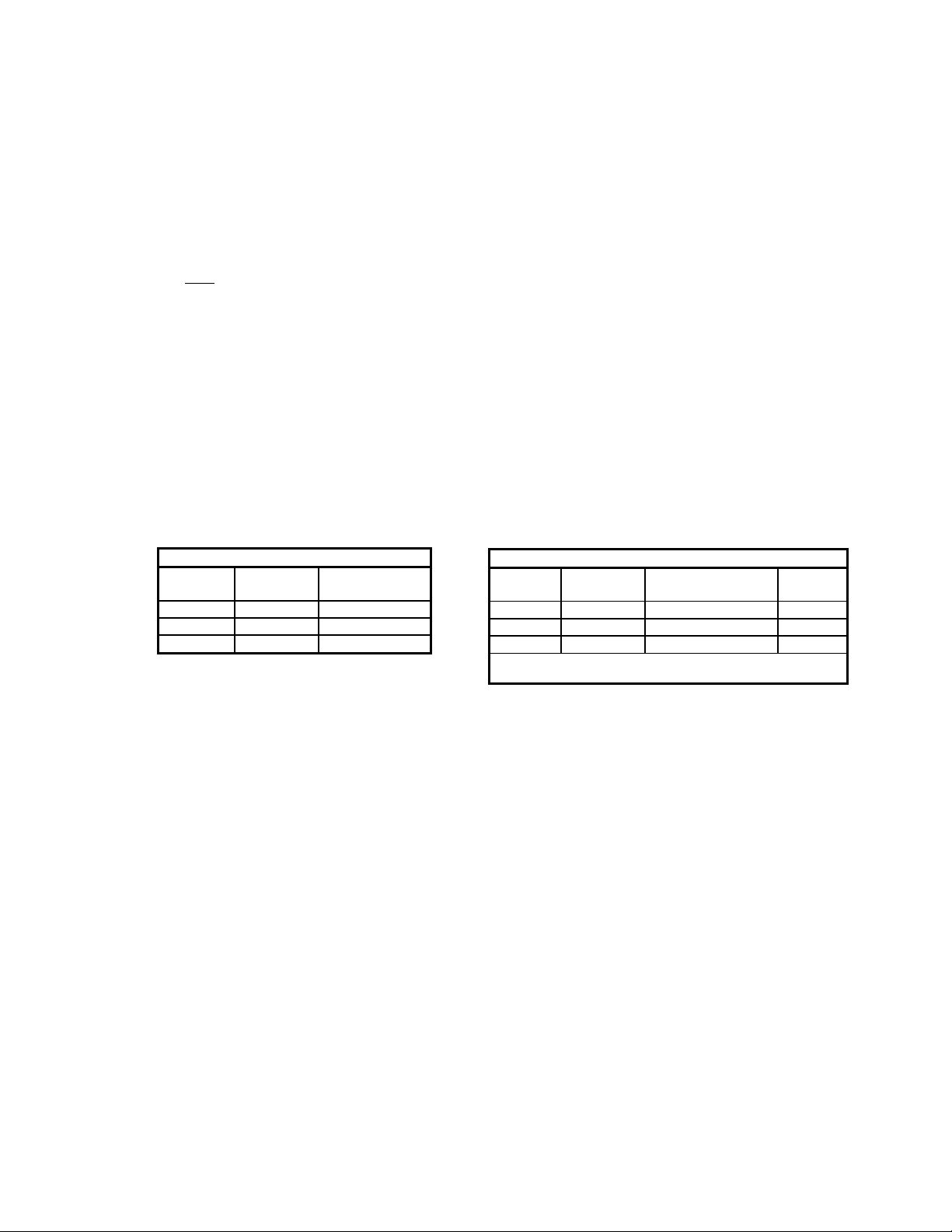
7. Set the valve carefully on the nozzle. Install the studs and tighten nuts hand tight. For stud selection for blind
tapped holes see Table 1 below :
TABLE 1: STUD SELECTION
Inlet
Flange
2" 5/8"-11 2.25"
3" 5/8"-11 2.50"
4" 5/8"-11 2.50"
8. Torque all fasteners to half the value listed in the Table 2 in a staggered, alternating pattern.
9. Make sure that the flanges are not distorted and that the gasket is evenly compressed.
10. Make up the final torque and check that no further nut rotation occurs at the specified torque value, as
specified in Table 2.
Thread
Size
Recommended
Stud Length
TABLE 2: BOLT TORQUE CHART, LB-IN [N-m]*
Inlet
Flange
*Average values based on a nitrile binder synthetic gasket, 1/32"
Raised Face Flat Face
2" 30 [3.4] 60 [6.8] 4
3" 54 [6.1] 108 [12.2] 4
4" 42 [4.7] 78 [8.8] 8
thick and lubricated threads.
Number
Bolts
Page 6

Page 6 of 18
PREVENTIVE MAINTENANCE
Groth Corporation recommends that all service performed on a pressure/vacuum relief valve be done at the factory or a factor y
authorized repair center. Trained mechanics with specialized test equipment will ensure that the valve is properly maintained
and accurately set.
It is important to regularly inspect and clean the diaphragm, guides and seating surfaces for the most effective valve
performance. Frequency of valve inspection and ma intenance should be based on the experience g ained in each application. It
is recommended that the valve be removed for inspection of wetted components at least once per year.
RECOMMENDED SPARE PARTS
The following spare parts should be stocked for maintenance purposes:
TABLE 3: PART NUMBER FOR RECOMMENDED SOFT GOOD SPARE PARTS
VALVE
SIZE
2"
3"
4"
FEP Diaphragm
20 mil
(Spring Loaded)
DPH1201027320 DPH1200027310 DPH1200027320 GKT1220027102 GKT1200027101
DPH1201037320 DPH1200037310 DPH1200037320 GKT1220037102 GKT1200037101
DPH1201047320 DPH1200047310 DPH1200047320 GKT1220047102 GKT1200047101
Setting
Diaphragm 10 mil 20 mil 10 mil 20 mil 10 mil 20 mil 10 mil 20 mil
Quantity 1 --- --- 1 1 1 --- 2
FEP Diaphragm
10 mil
(Weight Loaded)
FEP Diaphragm
20 mil
(Weight Loaded)
Gasket, Outlet
Fluoropolymer
(bottom)
Gasket, Cover
Fluoropolymer
TABLE 4: VALVE DIAPHRAGM USAGE, BASED ON SETTING
Weight-Loaded
Spring-Loaded
< 4 OSI 4 – 8 OSI
> 8 OSI
(top)
O-Ring
(machined pallet)
FKM
0267012U2
* Please provide the valve serial number and pressure/vacuum settings when ordering replacement parts.
TABLE 5: REPLACEMENT SPRING PART NUMBERS
Set
Range
PSIG
1.0 to 1.3
1.4 to 1.8
1.9 to 2.4
2.5 to 3.2
3.3 to 4.2
4.3 to 5.5
5.6 to 7.2
7.3 to 9.4
9.5 to 12.2
12.3 to 15.0
Carbon Steel Spring
Part Numbers
2" 3" 4" 2" 3" 4"
SPR1201020120 SPR1201030120 SPR1201040120 SPR1201020159 SPR1201030159 SPR1201040159
SPR1201020220 SPR1201030220 SPR1201040220 SPR1201020259 SPR1201030259 SPR1201040259
SPR1201020320 SPR1201030320 SPR1201040320 SPR1201020359 SPR1201030359 SPR1201040359
SPR1201020420 SPR1201030420 SPR1201040420 SPR1201020459 SPR1201030459 SPR1201040459
SPR1201020520 SPR1201030520 SPR1201040520 SPR1201020559 SPR1201030559 SPR1201040559
SPR1201020620 SPR1201030620 SPR1201040620 SPR1201020659 SPR1201030659 SPR1201040659
SPR1201020720 SPR1201030720 SPR1201040720 SPR1201020759 SPR1201030759 SPR1201040759
SPR1201020820 SPR1201030820 SPR1201040820 SPR1201020859 SPR1201030859 SPR1201040859
SPR1201020920 SPR1201030920 SPR1201040920 SPR1201020959 SPR1201030959 SPR1201040959
SPR1201021020 SPR1201031020 SPR1201041020 SPR1201021059 SPR1201031059 SPR1201041059
17-7 PH Stainless Steel Spring
Part Numbers
* To order original Groth replacement springs, find the desired pressure range fro m th e table and select the
corresponding part number for the valve size.
Page 7

Page 7 of 18
DISASSEMBLY
WEIGHT LOADED PALLET ASSEMBLY
1. Loosen and remove all hex nuts and washers.
2. Remove the vent cover or weatherhood from the valve body.
3. Remove the pallet assembly by firmly gra sping the stem and lifting up. Depending on the pressure/vacuum settin gs of the
particular valve, weight plates may have been added to the pallet assembly. T he weights and pallets must be reinstalled in
their original locations. Make sure that all weight plates stay with the appropriate pallet assembly. If working with more than
one valve tag the assemblies as they are removed from the valves.
4. Carefully inspect all guides for corrosion, damage or product build up. Also inspect the guide hole in the vacuum cover. Check
the metal seating surfaces for pitting or build up. It is recommended to replace all soft goods including diaphragm, O-Ring
(for machined pallets, Figure 2) and cover gasket.
TABLE 6: STEM LENGTH - IN [mm]
Valve Port (valve type)
Valve
Size
In [mm] Spring-Loaded Hollow-Stem Weight-Loaded Spring-Loaded Hollow-Stem Weight-Loaded
2" [50] 8.50 [215.9] 6.00 [152.4] 6.81 [172.97] 8.50 [215.9] 3.88 [98.55] 4.63 [117.6]
3" [80] 10.80 [274.3] -- 7.81 [198.37] 10.80 [274.3] -- 5.50 [139.7]
4" [100] 13.00 [330.2] 7.88 [200.15] 8.63 [219.2] 13.00 [330.2] -- 5.50 [139.7]
Pressure Port Vacuum Port
TABLE 7: RECOMMENDED PALLET
ASSEMBLY TORQUE
PALLET ASSEMBLY
TORQUE
STEM THREAD
SIZE
REQUIREMENT FT-LBS
[N-m]
METALLIC STEM
(ALUMINUM /
STAINLESS STEEL)
¼” 4 [5.4]
3/8” 16 [21.7]
NOTE: If the seat is damaged it must be lapped using a ground flat metal disc a nd a fine grit emer y c lot h attached to the disc.
Wipe seating surface clean before proceeding.
Figure 2 - Pallet Assembly Detail
5. Prior to final assembly, verify that the pallet and weights are back in their proper l ocation. Assemble in reverse order. Make
sure that pallet assembly is flat on the seat and that the stem is not cocked when the cover is installe d. Oil, grease or other
lubricant are not required on guides or other metal surface s of valves, and can hinder free movement. If the valve is in high
temperature service or stainless steel external fasteners ar e used, apply an anti-seize compound such as moly-disulfide to
all threaded components. Tighten all hex nuts firmly.
Page 8

Page 8 of 18
SPRING LOADED PALLET ASSEMBLY
1. Remove cap and hex jam nut.
2. Carefully measure and record the distance from the to p of the adjustment screw to the top of the spring chambe r. (Dimension
"D" - See Figure 3).
3. Relieve all spring compression by turning the adjustment screw counterclockwise.
4. Loosen and remove all hex nuts and washers.
5. Lift the spring chamber from the body.
6. Remove the upper spring button and spring. Remove the pallet ass embly by firmly gras ping the stem and lifting up. If more than
one valve is being disassembled, tag the assemblies as they are removed from the valves.
7. Carefully inspect all guides for corrosion, damage or product build up. Also inspect the adjustment screw and spring chamber
(#2) for thread damage or galling. Check the metal seating surfaces for pitting or build up. It is recommended that a ll soft goods
including diaphragms, O-Ring and spring chamber gasket be replaced.
NOTE: If the seat is damaged it must be lapped using a ground flat metal disc and a fine grit emery cloth attached to the disc.
Wipe seating surface clean before proceeding.
8. Prior to final assembly, verify that the pallet and spring are back in their proper location. Assemble in reverse order. Mak e sure
that pallet assembly is flat on the seat and that the stem is not cocked when the spring chamber is installed. Oil, grease or other
lubricant are not required on guides or other metal surfaces of valves, and can hin der free movement. L ubricate the ad justment
screw threads with an appropriate thread lubricant. If the valve is in high temperature service or stainless steel external
fasteners are used, apply an anti-seize compound such as moly-disulfide to all threaded components. Tighten all hex nuts
firmly.
9. If the spring is being re-used, compress it by turning the adjustment screw clockwise until the distance from the top of the
adjustment screw to the top of spring chamber matches the distance "D" measured in Step 2; proceed to Step 11.
10. If the spring is replaced, use only original springs supplied by Groth Corporation and follow the Procedure illustrated below:
11. Replace and tighten hex jam nut firmly. Replace cap.
FIGURE 3: SPRING SETTING PROCEDURE
STEP 1
After removing the adjustment
screw (#4) measure the
distance from top of spring
chamber to counter bore on
spring button for the dimension
"A".
STEP 2
Measure overall
length of
adjustment screw
for dimension "B".
STEP 3
This is the required
compression to achieve
the design set pressure.
Consult factory for
determination of “C”
dimension.
STEP 4
Use the following calculation to
obtain the "D" dimension.
Compress the spring by turning
the adjustment screw clockwise
accordingly.
D = B-A-C
Page 9

Page 9 of 18
TESTING AND SETTING PROCEDURE
1. Before starting to reassemble a valve, calculate the nominal pressure and vacuum pallet assembly weights, as shown in
Example 1. Weigh all pallet assemblies to ensure the correct settings. Record pallet assembly weight(s) on factory test
report.
Example: Pallet Assembly Weight Calculation (PAW)
6" Valve set at 7.5 OSI Read weight at 1.0 OSI from table 10 Weight = 3.04 Lb.
Multiple weight by set pressure PAW (*) = 3.04 x 7.5 = 22.8 Lb.
(*) = Includes pallet, retainer plate, stem, diaphragm, weight plates and fasteners.
TABLE 8 - NOMINAL PALLET ASSEMBLY WEIGHT
PER UNIT OF PRESSURE
(*)
Valve Size
SET
1.0 OSI 0..41 0.18 0.84 0.38 1.42 0.64
1.0 IN WC 0.24 0.11 0.48 0.22 0.82 0.37
1.0 mbar 0.09 0.04 0.19 0.09 0.33 0.15
2. After final assembling, mount the valve on a Tank Vent Test Stand and slowly raise the pressure at the flow rate specified
below:
ACCEPTANCE CRITERIA: The pressure gauge shall maintain a pressure equal to or greater than 75% of set pressure for a
one minute period while the specified flow rate is maintained. This test shall be successfully performed three consecutive
times.
3. If the valve fails to meet the 75% criteria, it must be disassembled and the seat, pallet, and or diaphragms repaired or replaced.
4. Set pressure and / or vacuum must also be tested. To test for set pressure / vacuum, slowly increase the pressure / vacuum to
the valve being tested. Increase until there is audible leakage from the valve seat. Closely monitor the p ressure / vacuum at
the gauge, when an increase in flow to the valve no longer raises the pressure at the gauge the set pressure / vacuum is
reached.
5. Repeat Step 4 three consecutive times. Record all three tests on the factory test report.
6. A copy of the Test Report shall be maintained with the Valve Maintenance Records.
2" 3" 4"
[Lb.] [kg] [Lb.] [kg] [Lb.] [kg]
Valve Size Test Flow Rate
2" - 4" 0.5 SCFH
19
Page 10

Page 10 of 18
MODEL INFORMATION
The nameplate on the Valve contains the Model Number, Serial Number, set pressures and flow capacity at a specified overpressure. The Model Number contains additional informatio n about m aterials of construction, s oft goods an d options. The fo llowing
chart will assist in relating the Model Number to the characteristics of your valve:
MODEL SIZE MATERIAL OPTIONS
------ ------ -------------
1721B 02" Pallet Z = Special Options
1722B 03" Seat O =No Specials
1723A 04" Body
1761A J = Steam Jacket
1 = Aluminum O = No Jacket
3 = Carbon Steel
5 = 316 SS
Z = Special SEAT MATERIAL
B = Buna-N
T = Fluoropolymer
V = FKM
M = Metal-to-Metal
Z = Special
EXAMPLE: 1721B-02-355-TOO indicates a 2" Model 1721B with Carbon Steel body, 316SS seat and pallet, Fluoropolymer
diaphragms and no special options.
PRODUCT LIMITED WARRANTY
Only Groth’s Product Limited Warranty terms apply to purchase orders accepted by Groth Corporation.
A. Seller warrants that products that are manufactured by Seller are manufactured in accordance with published specific ations
and free from defects in materials and/or workmanship for a period of (12) twelve months. Seller, at its option, will repair or
replace any products returned intact to the factory, transportation charges prepaid, which Seller, upon inspection,
determines to be defective in material and/or workmanship. T he foregoing shall co nstitute the sole r emedy for an y brea ch of
Seller’s warranty.
B. THERE ARE NO UNDERSTANDINGS, AGREEMENTS, REPRESENTATIONS, OR WARRANTIES, EXPRESS OR
IMPLIED (INCLUDING MERCHANTABILITY OR FITNESS FOR A PARTICULAR PURPOSE REGARDING PRODUCTS)
UNLESS SPECIFIED IN THE SALES CONTRACT. THIS CONTRACT STATES THE ENTIRE OBLIGATION OF SELLER.
Seller makes no warranties, either express or implied, except as provided herein, including without limitation thereof,
warranties as to marketability, merchantability, for a particular purpose or use, or against infringement of any patent of
products. In no event shall Seller be liable for any direct, incidental or consequential damages of any nature, or losses or
expenses resulting from any defective new product or the use of any such product, including any d amages for loss of time,
inconvenience, or loss of use of any such product.
C.The original Manufacturer shall be solely responsibl e for the design, development, supply, production, and performance of
its products hereunder, and the protection of its trade name or names, if any. It assu mes no responsibility, for products
modified or changed by its agent or customer, or any other third party. Any such modifications or c hanges to products sold
by Seller hereunder shall make the product limited warranty null and void.
D.Groth assumes no responsibility for products modified or changed by Customer or any other third party. Any such
modifications or changes to products sold by Groth hereunder sh all make the product limited warranty null and vo id. Groth
shall be under no obligation to manufacture, sell or supply, or to continue to manufacture, sell, or supply any of the pro ducts.
Page 11

Page 11 of 18
APPENDIX A: Groth Model 1721B Pressure/Vacuum Relief Valve
Page 12

Page 12 of 18
Groth Model 1721B Pressure/Vacuum Relief Valve
Bill of Material
ITEM DESCRIPTION STANDARD MATERIALS OF CONSTRUCTION
CARBON STEEL 316 SS
1 BODY CS (WCB) CF-8M (316 SS)
2 NUT, HEX SS SS
3 STUD SS SS
4 PLUG, PIPE CS SS
5 OUTLET CS (WCB) CF-8M (316 SS)
6 STUD SS SS
7 NUT, HEX SS SS
8 WASHER, LOCK SS SS
9 * GASKET - COVER PTFE PTFE
10 CHAMBER, SPRING CS (WCB) CF-8M (316 SS)
11 GASKET, CAP SS SS
12 CAP CS 316 SS
13 NUT, HEX JAM SS SS
14 SCREW, ADJUSTMENT 316 SS 316 SS
15 STEM, PRESSURE 316 SS 316 SS
16 BUTTON, SPRING 316 SS 316 SS
17 SPRING CS 17-7 PH SS
18 ROD, GUIDE 316 SS 316 SS
19 PALLET, PRESSURE 316 SS 316 SS
20 * DIAPHRAGM, PRESSURE FEP FEP
21 PLATE, RETAINER (PRESSURE) 316 SS 316 SS
22 NUT, HEX LOCK SS SS
23 * O-RING FKM FKM
24 * GASKET, INLET PTFE PTFE
25 COVER CS (WCB) AL (GR. 356 T6)
26 WASHER, LOCK SS SS
27 NUT, HEX SS SS
28 STEM, VACUUM 316 SS 316 SS
29 ROD, GUIDE 316 SS 316 SS
30 * GASKET, COVER PTFE PTFE
31 PALLET, VACUUM 316 SS 316 SS
32 * DIAPHRAGM, VACUUM FEP FEP
33 PLATE, RETAINER (VACUUM) 316 SS 316 SS
34 SCREEN (OPTIONAL) 316 SS 316 SS
35 O-RING (PLATE PALLET) FKM FKM
36 INSERT, SEAT (NOT SHOWN) 316 SS N/A
37 PALLET WEIGHT (NOT SHOWN) LEAD LEAD
* SPARE PARTS
Page 13

Page 13 of 18
APPENDIX B: Groth Model 1722B Pressure/Vacuum Relief Valve
Page 14

Groth Model 1722B Pressure/Vacuum Relief Valve
Bill of Material
ITEM DESCRIPTION STANDARD MATERIALS OF CONSTRUCTION
CARBON STEEL 316 SS
1 BODY CS (GR. WCB) 316 SS(GR. CF8M)
2 STUD SS SS
3 HEX NUT SS SS
4 LOCK WASHER SS SS
5 PIPE PLUG CS 316 SS(GR. CF8M)
6 OUTLET CS(GR. WCB) 316 SS
7 LOCK WASHER SS SS
8 HEX NUT SS SS
9 STUD SS SS
10 COVER CS(GR. WCB) 316 SS(GR. CF8M)
11 PRESSURE STEM 316 SS 316 SS
12 * COVER GASKET PTFE PTFE
13 GUIDE ROD 316 SS 316 SS
14 PRESSURE PALLET 316 SS 316 SS
15 * PRESSURE DIAPHRAGM, PRIMARY FEP FEP
16 * PRESSURE DIAPHRAGM, BACKUP FEP FEP
17 PRESSURE RETAINER PLATE 316 SS 316 SS
18 FLAT WASHER SS SS
19 HEX EXPANDING LOCK NUT SS SS
20 * INLET GASKET PTFE PTFE
21 GUIDE ROD 316 SS 316 SS
22 SPRING CHAMBER CS(GR. WCB) 316 SS(GR. CF8M)
23 * CAP GASKET 316 SS 316 SS
24 CAP CS 316 SS
25 HEX NUT SS SS
26 ADJUSTMENT SCREW 316 SS 316 SS
27 SPRING BUTTON 316 SS 316 SS
28 SPRING CS 17-7 PH SS
29 VACUUM STEM 316 SS 316 SS
30 VACUUM PALLET 316 SS 316 SS
31 * VACUUM DIAPHRAGM, PRIMARY FEP FEP
32 * VACUUM DIAPHRAGM, BACKUP FEP FEP
33 VACUUM RETAINER PLATE 316 SS 316 SS
34 * O-RING FKM FKM
35 HEX EXPANDING LOCK NUT SS SS
36 * O-RING (MACHINED PALLET) FKM FKM
37 VACUUM SCREEN ASSY. (OPTIONAL) 316 SS 316 SS
38 SEAT INSERT (NOT SHOWN) 316 SS N/A
39 PALLET WEIGHT(NOT SHOWN) LEAD LEAD
* SPARE PARTS
Page 14 of 18
Page 15

Page 15 of 18
APPENDIX C: Groth Model 1723A Pressure/Vacuum Relief Valve
Page 16

Groth Model 1723A Pressure/Vacuum Relief Valve
Bill of Material
ITEM DESCRIPTION STANDARD MATERIALS OF CONSTRUCTION
CARBON STEEL 316 SS
1 BODY CS (GR. WCB) 316 SS(GR. CF8M)
2 STUD SS SS
3 HEX NUT SS SS
4 LOCK WASHER SS SS
5 PIPE PLUG CS 316 SS
6 OUTLET CS(GR. WCB) 316 SS(GR. CF8M)
7 GUIDE ROD 316 SS 316 SS
8 * COVER GASKET PTFE PTFE
9 STUD SS SS
10 HEX NUT SS SS
11 LOCK WASHER SS SS
12 SPRING CHAMBER CS(GR. WCB) 316 SS(GR. CF8M)
13 * CAP GASKET 316 SS 316 SS
14 CAP CS 316 SS
15 * HEX NUT SS SS
16 * ADJUSTMENT SCREW 316 SS 316 SS
17 SPRING BUTTON 316 SS 316 SS
18 SPRING CS 17-7 PH SS
19 PRESSURE STEM 316 SS 316 SS
20 PRESSURE PALLET 316 SS 316 SS
21 * PRESSURE DIAPHRAGM, PRIMARY FEP FEP
22 * PRESSURE DIAPHRAGM, BACKUP FEP FEP
23 PRESSURE RETAINER PLATE 316 SS 316 SS
24 * O-RING FKM FKM
25 HEX EXPANDING LOCK NUT SS SS
26 * INLET GASKET PTFE PTFE
27 GUIDE ROD 316 SS 316 SS
28 VACUUM STEM 316 SS 316 SS
29 VACUUM PALLET 316 SS 316 SS
30 * VACUUM DIAPHRAGM, PRIMARY FEP FEP
31 * VACUUM DIAPHRAGM, BACKUP FEP FEP
32 VACUUM RETAINER PLATE 316 SS 316 SS
33 VACUUM SCREEN ASSY. (OPTIONAL) 316 SS 316 SS
34 SEAT INSERT (NOT SHOWN) 316 SS N/A
* SPARE PARTS
Page 16 of 18
Page 17

Page 17 of 18
APPENDIX D: Groth Model 1761A Pressure/Vacuum Relief Valve
Page 18

Page 18 of 18
Groth Model 1761A Pressure/Vacuum Relief Valve
Bill of Material
ITEM DESCRIPTION
CARBON ST L 316 SS
1 OUTLET CS WCB CF-8M (316 SS)
2 PLUG, PIPE CS 316 SS
3 * GASKET, COVER PTFE PTFE
4 STUD SS SS
5 NUT, HEX SS SS
6 WASHER, LOCK SS SS
7 CHAMBER, SPRING CS WCB CF-8M (316 SS)
8 GASKET, CAP SS SS
9 CAP CS 316 SS
10 NUT, HEX JAM SS SS
11 SCREW, ADJUSTMENT 316 SS 316 SS
12 STEM, PRESSURE 316 SS 316 SS
13 BUTTON, SPRING 316 SS 316 SS
14 SPRING CS 17-7 PH SS
15 ROD, GUIDE 316 SS 316 SS
16 PALLET, PRESSURE 316 SS 316 SS
17 * DIAPHRAGM, PRESSURE FEP FEP
18 PLATE, RETAINER (PRESSURE) 316 SS 316 SS
19 * GASKET, INLET PTFE PTFE
20 STUD SS SS
21 NUT, HEX SS SS
22 WASHER, LOCK SS SS
23 INLET CS WCB CF-8M (316 SS)
24 NUT, HEX LOCK SS SS
25 * O-RING FKM FKM
26 INSERT, SEAT (NOT SHOWN) 316 SS N/A
* SPARE PARTS
STANDARD MATERIALS OF CONSTRUCTION
 Loading...