

Page 1
Installation, Operation and Maintenance Manual for
Pressure/Vacuum Relief Valves
Models 1720A, 1760A
IOM 1700A
January 2006
IOM 1700A
REV. A 12541
Page 2

TABLE OF CONTENTS:
pumping rates and the temperature. Refer to
API Standard 2000 for the procedures to
DESCRIPTION PAGE
Introduction 2
Valve Design & Function 3
Safety Warnings 4
Inspection and Storage 4
Installation 4 & 5
Maintenance 6 & 7
Test Procedure & Weight Blocks 8 & 9
Bill of Materials & Submittal Drawings
Model 1720A 10
Model 1760A 11
Abbreviations 11
Model Identification 12
Product Limited Warranty 12
LIST OF FIGURES
Fig. 1- Typical Tank Installation 3
Fig. 2- Pressure Relief - Operation 3
Fig. 3- Vacuum Relief - Operation 3
Fig. 4- Pallet Assembly Detail/ Valve
7
Cross Section
LIST OF TABLES
Table 1 - Bolt Torque (Installation) 5
Table 2 - Valve Weights (Maximum) 5
Table 3 - Stem Length (Maintenance) 6
Table 4 - Spare Parts P/N 7
Table 5 - Pallet Assembly Weights 8
Table 6 - Maximum settings 8
Table 7 - Weight Block Dimensions 9
INTRODUCTION:
determine venting requirements.
A relief valve must be carefully maintained by
a qualified valve technician. It should only be
assembled under clean conditions, preferably
in a service shop environment. Carefully read
and understand this manual before installing
or attempting to repair a valve. Groth
Corporation or a factory authorized repair
center offers repair services for all products
manufactured by the Tank Protection
Division.
The table below shows the two different valve
Models covered in this manual and indicates
their Pressure (P) and/or Vacuum (V) relief
capabilities.
Model P V Description
1720A
1760A
Vent to Header
For a list of abbreviations used in this manual,
refer to page 11. For information not
contained in this manual, please contact:
Groth Corporation
13650 N. Promenade Blvd.
Stafford, Texas 77477, USA
(281) 295-6800 (Office)
(281) 295-6999 (Fax)
The nameplate below shows the basic
information that is listed for each relief valve:
Vent to Header
Pressure and/or vacuum relief valves are
used on liquid storage tanks and other
process vessels or systems to prevent
structural damage due to excess internal
pressure or vacuum.
Storage tanks are pressurized when liquid is
pumped in, compressing the existing vapor or
when rising temperatures cause increased
evaporation or expansion of existing vapor.
Conversely, a vacuum condition may be
created when pumping out or due to falling
temperature. To prevent tank damage, vapor
must be allowed into or out of the tank at
specified pressure/vacuum conditions. The
volume rate of venting depends upon the tank
size, volatility of the tank contents, the
2
GROTH
CORPORATION
STAFFORD
TEXAS
USA
SETTING
2 OSI
1 OSI
1760A-03-355-TOO
MD:
S/N:
117405-10-1
PSV-440
TAG:
FLANGE:
TYPE
PRESS.
VAC.
A CONTINENTAL DISC COMPANY
3" X 3" 150# RF
% OP
100
30
100
FLOW [SCMH]
26,600
15,694
14,500
Page 3
VALVE DESIGN AND FUNCTION:
SEE NOTE 3
1720A
PRESSURE/VACUUM
RELIEF VALVE
BLANKET GAS REGULATOR
EMERGENCY RELIEF VALVE
SEE NOTE 2
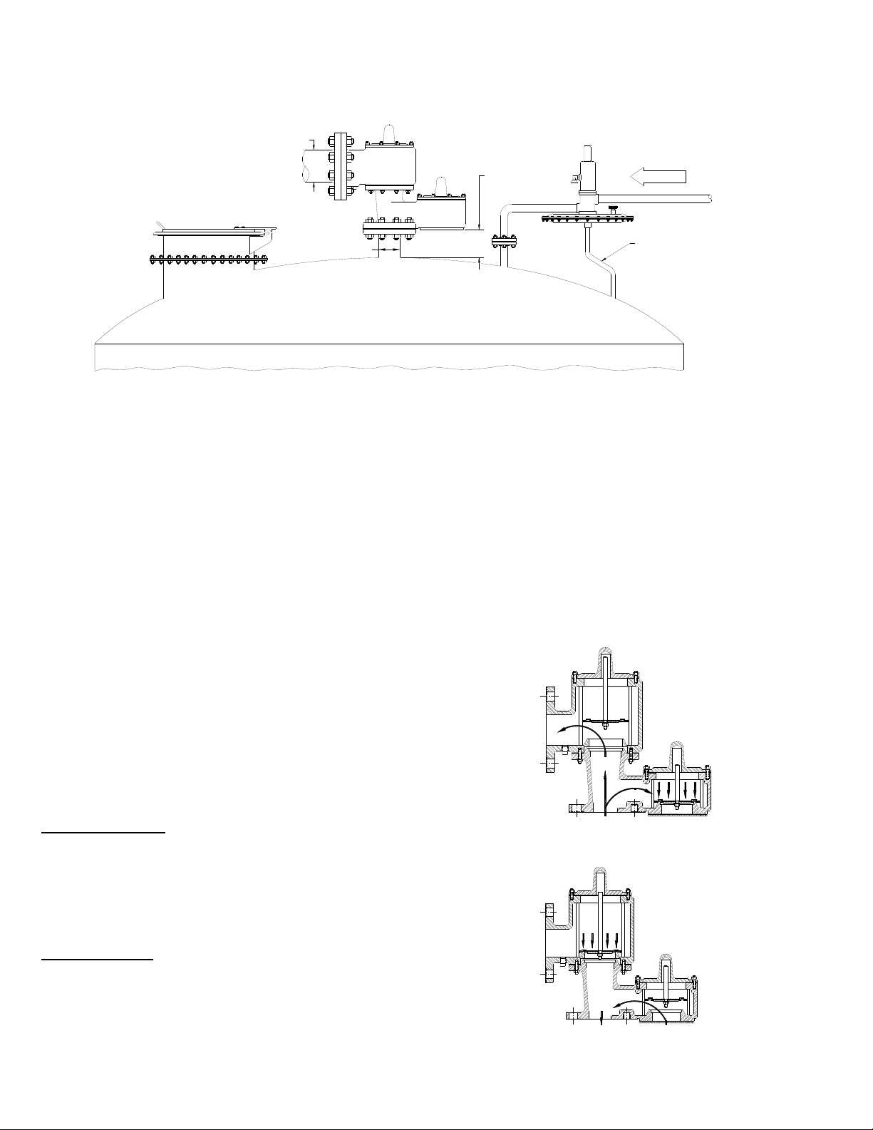
Fig. 1 - Typical Tank Installation
Tank protection equipment typically includes
an operating valve which is designed to
provide pressure/vacuum relief under normal
pump in/out and thermal breathing conditions.
An emergency relief valve can also provide
both pressure and vacuum relief and normally
it is sized to provide pressure relief if there is
a fire in the immediate vicinity of the tank. It
may also be sized by the tank designer to
provide protection in the event of equipment
failure (such as the rupture of a process
steam line or an inert gas blanketing system
failing “wide open”) or operator error.
SEE NOTE 1
FLOW
TUBING
Installation Notes: (See Fig. 1 above)
1. Minimum clearance between tank roof and
vacuum inlet port must be at least equal to
the valves’ nominal flange bore.
2. Tank nozzle bore must be > or = valve
inlet flange bore.
3. Inlet and outlet piping loads must be
supported by appropriate structural
supports, NOT by the valve body.
A typical tank installation is shown in Fig. 1
which includes the following Groth products:
Model 1720A ‘P/V’ Weight Loaded Valve
Model 3000 Gas Blanketing Regulator
Model 2400 Emergency ‘P’ Relief Valve
Pressure Relief: As the pressure in the
storage tank increases, the vacuum pallet is
held shut. When the set pressure is reached,
the pressure pallet lifts and relieves to
atmosphere (or to a header if it is a pipe away
valve). See Fig. 2.
Vacuum Relief: As a vacuum is drawn in the
storage tank (for example, when fluid is being
pumped out), the pressure pallet is held shut
by atmospheric pressure. When the vacuum
setting is reached, the pallet lifts and air is
drawn in from the atmosphere. See Fig. 3.
Fig. 2- Pressure Relief
Fig. 3 - Vacuum Relief
3
Page 4

SAFETY WARNINGS:
This section is an overview of safety
guidelines that should be followed during the
installation, operation and maintenance of
Groth Pressure/ Vacuum Relief Valves. To
understand the context of these instructions
and warnings, it is necessary to completely
read and understand the contents of this
manual.
The purpose of a weight loaded
pressure/vacuum relief valve is to prevent
excessive pressure or vacuum in a tank or
process system. The valve must be designed
for the proper MAWP and flow requirements
of the system. Consult API Standard 2000 for
tank protection sizing procedures. An
improperly specified or functioning relief valve
may result in structural damage to the tank or
system, and can cause severe personal injury
or death.
Valves are set at the factory according to
purchase specifications. Do NOT change
pressure ratings by adding additional weights
to the pallet assembly without consulting the
factory or your local Groth representative.
Adding weights to a valve may restrict pallet
lift and reduce the valves’ rated flow capacity.
INSPECTION AND STORAGE:
The pressure/vacuum relief valve is carefully
packaged to prevent damage or
contamination during shipping. Inspect all
equipment when it is received; report any
damage to the carrier immediately. The valve
should be protected during handling and
storage. Keep all the ports plugged to
prevent intrusion of foreign materials. Before
installation, inspect the unit for indications of
physical damage or internal contamination. If
these are observed, the valve must be
disassembled, cleaned and repaired before
installation.
INSTALLATION:
A typical valve installation on a tank or vessel
is illustrated in Fig.1 on Page 3 using a Model
1720A Pressure/Vacuum Relief Valve.
DO NOT mix pressure/vacuum pallet
assemblies. Failure to ensure that both pallet
assemblies are installed in the correct
location can change the pressure and
vacuum relief settings. This can cause a tank
failure.
DO NOT attempt to remove the valve from
the tank or process vessel without first
bleeding all pressure from the system.
ALTERNATIVE MEANS OF PRESSURE
RELIEF MUST BE PROVIDED WHEN THE
VALVE IS OUT OF SERVICE.
If the valve has been exposed to process
vapors while in service. Observe all plant
procedures and Material Safety Data Sheets
(MSDS) for the products in the system when
inspecting, adjusting or servicing the valve.
Take appropriate safety precautions
regarding eye protection, respiration and skin
contact.
The tank pressure required to discharge the
normal or emergency venting requirements of
the tank will be increased by the amount of
back pressure in the discharge header, on a
pipe away valve configuration. Maximum
possible discharge header pressure must be
considered when sizing the pressure relief
valve.
Groth's weight loaded Pressure/Vacuum
Relief Valves are designed to provide tank
protection for both pressure and/or vacuum to
+/-1 PSIG settings. The valves provide full
rated flow capacity at 100% over-pressure.
Consult factory for performance under other
conditions.
WARNING: The valve must be installed in a
vertical position as shown in Fig 1. To
achieve nominal flow capacity, the tank
nozzle bore must be at least the same
nominal dimension as the relief valve inlet
body.
This series of valves all have 150# ANSI
flange drilling compatibility. Torque
guidelines are listed in Table 1. The valves
are NOT rated for full flange pressure and do
not require high bolting torque. Consult
factory for special applications.
4
Page 5

The following guidelines should be
observed at installation:
1. Inspect the gasket seating surface of the
tank nozzle flange. It must be clean, free
of scratches, corrosion, tool marks, and
flat.
2. Aluminum valves are furnished with flat
face flanges; they should only be installed
on a mating flat face flange with a full
faced gasket.
3. Inspect the gasket; make sure that the
material is suitable for the application.
4. Lubricate all studs and nuts with an
appropriate thread lubricant. If the valve
will see high temperature service or
stainless steel fasteners are used, apply
an anti-seize compound such as molydisulfide.
TABLE 1 - Bolt Torque & Stud Specifications - ANSI #150 Flange Connections
Mounting Stud Torque - Lb.In.(kg.m) Number of Special Stud Specifications*
5. Center the gasket within the bolt circle.
6. Set the valve carefully on the nozzle.
Install the studs and tighten nuts hand
tight. For studs selection for blind tapped
holes see Table 1.
7. Torque all fasteners to half the value listed
in Table 1 in a staggered, alternating
pattern.
8. Make sure that the flanges are not
distorted and that the gasket is evenly
compressed. Make up the final torque
and check that no further nut rotation
occurs at the torque value specified on
Table 1 below:
Flange Raised Face Flat Face
2" 30 (0.35) 60 (0.69) 4 5/8" - 11 2.25" 2
3" 54 (0.62) 108 (1.24) 4 5/8" - 11 2.50" 2
4" 42 (0.48) 78 (0.89) 8 5/8" - 11 2.50" 4
(*) - Blind tapped holes only (1720A). Use standard ANSI stud length for other holes.
TABLE 2 - Valve Weights @ Maximum Settings (Carbon Steel) - Lb. (kg)
Valve Size 1720A 1760A
2" 91 (41) 57 (26)
3" 128 (58) 86 (39)
4" 190 (86) 119 (54)
Studs Thread
UNC*
Stud
Length *
Qty *
5
Page 6

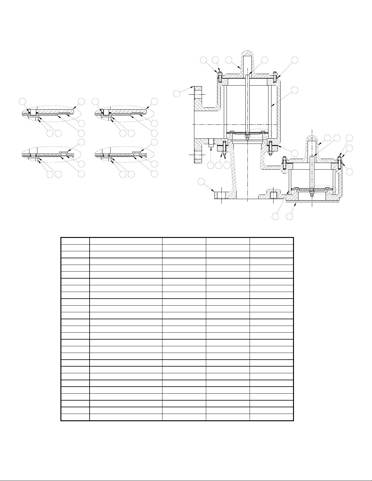
MAINTENANCE:
Groth Corporation recommends that all
service performed on a pressure/vacuum
relief valve be done at the factory or a factory
authorized repair center. Trained mechanics
with specialized test equipment will ensure
that the valve is accurately set.
It is important to regularly inspect the
diaphragm, guides and seating surfaces to
ensure the valve can open freely. Refer to
Fig. 4 on the next page that illustrates a
typical Pressure/Vacuum relief valve when
disassembling the unit.
WARNING: Before disassembling valve
carefully read and understand the Safety
Warnings listed on page 3.
disc and fine grit lapping compound attached
to the disc. Wipe the seating surface clean
before proceeding.
5. If the stems are being replaced, check
Table 3 to ensure that the correct length is
being used in both the pressure and vacuum
ports.
TABLE 3 - Stem Length - In. (cm)
Valve Valve Model
Size Pressure Vacuum
[In] Port Port
2
3
4
6.81
(17.3)
7.81
(19.8)
8.63
(21.9)
4.63
(11.8)
5.50
(14.0)
5.50
(14.0)
1. Loosen and remove all nuts (#1).
2. Lift off the pressure (#2) and vacuum (#3)
covers.
3. Remove the vacuum and pressure pallet
assemblies by firmly grasping the stems (#4 &
#5) and lifting up. Depending on the
pressure/vacuum settings of the particular
valve, weight plates may have been added to
the pallet assemblies. The weights and
pallets must be reinstalled in their original
locations. Make sure that all weight plates
stay with the appropriate pallet assembly.
Tag the assemblies "Pressure" and "Vacuum"
as they are removed from the valve.
4. Carefully inspect all guides (#6 & #7) for
corrosion, damage or product build up. Also
inspect the guide hole in the pressure (#2)
and vacuum (#3) covers. Check the metal
seating surfaces for pitting, corrosion or
product build up. It is recommended to
replace all soft goods including diaphragms
(#8 & #9), O-Ring (#10) and cover gasket
(#11). For a list of recommended spare parts
see Table 4.
NOTE: If the seats are damaged they must
be lapped using a perfectly flat ground metal
6. Verify that the pallets and weights are
back in their proper location. Assemble in
reverse order, observing the maximum
dimensions for the weight blocks as listed in
Table 7 on Page 8. Make sure that pallet
assemblies sit flat on the seat and that the
stem is not cocked when the pressure (#2)
and vacuum (#3) covers are installed.
Tighten all nuts (#1) firmly.
WARNING: When assembling a P/V valve,
always use the correct length stem (as specified
in Table 3), put the pressure and vacuum pallet
assemblies back in their original location and
ensure that the stem is straight and fits into the
guide in the cover.
1. If the stem length is too long, pallet lift will be
restricted and the valve will not attain its full
rated flow capacity.
2. If the pressure and vacuum pallet assemblies
are mixed at assembly, the settings will be
changed.
If the stem is cocked at an angle, pallet lift may be
completely blocked. An over-pressure can occur
if any of these three conditions happens. This
can cause a tank failure, severe personal injury
and material damage.
6
Page 7

TABLE 4: Part Numbers - Spare Parts *
Valve Size
Component 2" 3" 4"
FEP Diaphragm, 10 mil
FEP Diaphragm, 20 mil
Gasket, Outlet (bottom)
Gasket, Cover (top)
O-Ring (plate pallet) -FKM
Setting < 4 OSI 4 - 8 OSI 8 - 12 OSI 12 - 16 OSI
Diaphragm 10 mil 20 mil 10 mil 20 mil 10 mil 20 mil 10 mil 20 mil
Quantity 1 --- --- 1 1 1 --- 2
* Please provide the valve serial number and pressure/vacuum settings when ordering replacement parts.
80040162 80040362 80040562
80040154 80040357 80040568
93158001 93158002 93158003
93158008 93158009 93158010
89107010 ( #010 70 durometer)
10
PRESSURE PALLET
ASSEMBLY DETAILS
PLATE PALLET
SPUN OR STAMPED
PALLET
1
VACUUM PALLET
ASSEMBLY DETAILS
10
8
8
PLATE PALLET
SPUN OR STAMPED
PALLET
9
9
2 4 11
Fig. 4 - Pallet Assembly Details/ Valve Cross Section
6
7
3 5
1
11
7
Page 8
TEST PROCEDURE:
minute period while the specified flow rate is
maintained.
1. A chart showing nominal pallet assembly
weights for three common units of pressure is
shown below in Table 5. Before starting to
reassemble a valve, calculate the nominal
pressure and vacuum pallet assembly
weights. Weigh both pallet assemblies to
ensure the correct settings.
2. After final assembling, mount the valve on
a Tank Vent Test Stand (TVTS) and slowly
raise the pressure to achieve a flow rate of .5
SCFH.
ACCEPTANCE CRITERIA: The pressure
gauge shall maintain a pressure equal to or
greater than 75% of set pressure for a one-
3. If the valve fails to meet the 75% criteria, it
must be disassembled and the seat, pallet,
and or diaphragms repaired or replaced.
4. Complete a Test Report indicating the
actual pallet assembly weight and the peak
pressure achieved at the specified Test Flow
Rate.
5. A copy of the Test Report shall be
maintained with the Valve Maintenance
Records.
TABLE 5 - Nominal Pallet Assembly Weight Per Unit of Pressure (*)
Valve Size
SET
1.0 OSI
1.0 IN WC
1.0 mbar
2" 3" 4"
[Lb.] [kg] [Lb.] [kg] [Lb.] [kg]
0.41 0.18 0.84 0.38 1.42 0.64
0.24 0.11 0.48 0.22 0.82 0.37
0.09 0.04 0.19 0.09 0.33 0.15
Example: Pallet Assembly Weight Calculation (PAW)
4" Valve set at 7.5 OSI Read weight at 1.0 OSI from table Weight = 1.42 Lb.
Multiple weight by set pressure PAW (*)= 1.42 x 7.5 = 10.7 Lb.
(*) = Includes pallet, retainer plate, stem, diaphragm, weight plates and fasteners.
The following Table shows the maximum pressure and vacuum settings for the weight loaded
1720A relief valve that can be achieved without the use of special spacer rings between the cover
and body. Consult the factory for higher settings.
TABLE 6- Maximum Vacuum Settings With Lead Weights & No Spacer Ring
Valve Size OSI IN WC mbar
Vacuum 2"-3"-4" 10 17 43
Pressure 2"-3"-4" 33 57 142
WARNING: Table 7 on Page 9 shows the maximum envelope dimensions for the weight blocks to
ensure that a valve will achieve rated flow capacity. DO NOT exceed these dimensions as pallet
lift could be restricted. Pallet lift restriction can cause the tank to be over-pressured to achieve the
valves’ rated flow capacity.
8
Page 9

TABLE 7 - Weight Blocks Maximum Envelope Dimensions - In. (cm)
Warning:
See Page 7
ØA
ØB
Dimensions: A,B,C & D
Apply to Models:
1720A and 1760A
D
C
ØE
ØF
Dimensions: E,F,G & H
Apply to Model:
H
G
1720A
Model
SIZE
“A” DIA. “B” DIM. “C” DIA.“D” DIM. “E” DIA “F” DIM. “G” DIA. “H” DIM.
3.00" (7.6) 2.75 " (70) 2.56" (6.5) 1.00" (2.5) 3.25" (8.2) 0.56" (1.4) 3.06" (7.8) 1.00" (2.5)
2"
4.25" (11) 3.75 " (9.5) 2.75" (7.0) 1.00" (2.5) 4.50" (11) 0.56" (1.4) 4.00" (10) 1.00" (2.5)
3"
5.25" (13) 4.75" (12) 3.38" (8.6) 1.00" (2.5) 5.50" (14) 0.69" (1.7) 5.00" (13) 1.00" (2.5)
4"
1720A/1760A 1720A
Outlet - Pressure Body - Vacuum
9
Page 10
Groth Model 1720A Pressure/Vacuum Relief Valve
7
6 8 9
10
PRESSURE PALLET
ASSEMBLY DETAILS
26
17
18
PLATE PALLET
17
18
SPUN OR STAMPED
PALLET
12
13
14
12
13
14
ASSEMBLY DETAILS
26
VACUUM PALLET
18 17
PLATE PALLET
18
17
SPUN OR STAMPED
PALLET
5
22
23
24
22
23
24
Fig. 7
ITEM DESCRIPTION CARBON ALUMINUM STAINLESS
1 Body CS Aluminum 316 SS
2 Nut, Hex 316 SS 316 SS 316 SS
3 Stud 316 SS 316 SS 316 SS
4 Plug, Pipe CS CS 316 SS
5 Outlet CS Aluminum 316 SS
6 Stud 316 SS 316 SS 316 SS
7 Nut, Hex 316 SS 316 SS 316 SS
8 Cover, Pressure CS Aluminum 316 SS
9 Stem, Pressure 316 SS 316 SS 316 SS
10 Gasket, Cover * Fluoropolymer Fluoropolymer Fluoropolymer
11 Rod, Guide 316 SS 316 SS 316 SS
12 Pallet, Pressure 316 SS 316 SS 316 SS
13 Diaphragm, Pressure * Fluoropolymer Fluoropolymer Fluoropolymer
14 Plate, Retainer (Pressure) 316 SS 316 SS 316 SS
15 Gasket, Inlet * Fluoropolymer Fluoropolymer Fluoropolymer
16 Cover CS Aluminum 316 SS
17 Washer, Lock 316 SS 316 SS 316 SS
18 Nut, Hex 316 SS 316 SS 316 SS
19 Rod, Guide 316 SS 316 SS 316 SS
20 Stem, Vacuum 316 SS 316 SS 316 SS
21 Gasket, Cover * Fluoropolymer Fluoropolymer Fluoropolymer
22 Pallet, Vacuum 316 SS 316 SS 316 SS
23 Diaphragm, Vacuum * Fluoropolymer Fluoropolymer Fluoropolymer
24 Plate, Retainer (Vacuum) 316 SS 316 SS 316 SS
25 Screen (Optional) SS Aluminum SS
26 O-Ring, (Plate Pallet) * FKM FKM FKM
* = Recommended Spare Parts
11
2016
6
15
4
2 3
1
19 25
7
21
10
Page 11

Groth Model 1760A Pressure/Vacuum Relief Valve
17
ITEM DESCRIPTION CARBON ALUMINUM STAINLESS
1 Outlet CS Aluminum 316 SS
2 Cover CS Aluminum 316 SS
3 Stem 316 SS 316 SS 316 SS
4 Stud 316 SS 316 SS 316 SS
5 Nut, Hex 316 SS 316 SS 316 SS
6 Gasket, Cover * Fluoropolymer Fluoropolymer Fluoropolymer
7 Rod, Guide 316 SS 316 SS 316 SS
8 Pallet, Pressure 316 SS 316 SS 316 SS
9 Diaphragm, Pressure * Fluoropolymer Fluoropolymer Fluoropolymer
10 Plate, Retainer (Pressure) 316 SS 316 SS 316 SS
11 Gasket, Inlet * Fluoropolymer Fluoropolymer Fluoropolymer
12 Stud 316 SS 316 SS 316 SS
13 Nut, Hex 316 SS 316 SS 316 SS
14 Inlet CS Aluminum 316 SS
15 Washer, Lock 316 SS 316 SS 316 SS
16 Nut, Hex 316 SS 316 SS 316 SS
17 O-Ring (Plate Pallet) * FKM FKM FKM
18 Plug, Pipe CS CS 316 SS
* = Recommended Spare Parts
LIST OF ABBREVIATIONS
ANSI American National Standard
API American Petroleum Institute
cm Centimeter
ERV Emergency Relief Valve
In. Inches
In. WC Inches Of Water Column
kg Kilogram
kg.m Kilogram-meter
Lb. Pound
Lb.In. Pound Inch
PRESSURE PALLET
ASSEMBLY DETAILS
PLATE PALLET
SPUN OR STAMPED
PALLET
8
9
10
8
9
10
Fig 8
MAWP Max Allowable Working
Press.
Max. Maximum
MD Model
mil Thousands Of An Inch
Min. Minimum
mm Millimeter
MSDS Material Safety Data Sheet
OP Over Pressure
OSI Ounces Per Square Inch
OZ Ounces
1
2
16 1518 14
43
5
6
7
11
13
12
P Pressure
P/N Part Number
POV Pilot Operated Valve
PSIG Pounds Per Square Inch
S/N Serial Number
SCFH Standard Cubic Ft Per Hour
SLV Spring Loaded Valve
TVTS Tank Vent Test Stand
V Vacuum
WLV Weight Loaded Valve
11
Page 12
The nameplate on the Valve contains the Model Number, Serial Number, set pressures and flow
capacity at a specified over-pressure. The Model Number contains additional information about
materials of construction, soft goods and options. The following chart will assist in relating the
Model Number to the characteristics of your valve:
MODEL SIZE MATERIAL OPTIONS
----- ------ -------------
1720A 02" Pallet Z = Special Options
1760A 03" Seat O = No Specials
04" Body
1 = Aluminum J = Steam Jacket
3 = Carbon Steel O = No Steam Jacket
5 = 316 SS S = Spacer
Z = Special H = Steam Jacket & Spacer
SEAT MATERIAL
B = Buna-N
T = Fluoropolymer
V = FKM
Z = Special
EXAMPLE: 1720A-02-355-TOO indicates a 2" x 2” Model 1720A with Carbon Steel body and 316
SS seat, 316SS pallet, Fluoropolymer seat diaphragms and no special options.
PRODUCT LIMITED WARRANTY
A. Seller warrants that products which are
manufactured by Seller, are manufactured in
accordance with published specifications and
free from defects in materials and/or
workmanship for a period of (12) twelve months.
Seller, at its option, will repair or replace any
products returned intact to the factory,
transportation charges prepaid, which Seller,
upon inspection, shall determine to be defective
in material and/or workmanship. The foregoing
shall constitute the sole remedy for any breach
of Seller's warranty.
B. THERE ARE NO UNDERSTANDINGS,
AGREEMENTS, REPRESENTATIONS, OR
WARRANTIES, EXPRESS OR IMPLIED,
(INCLUDING MERCHANTABILITY OR
FITNESS FOR A PARTICULAR PURPOSE
REGARDING PRODUCTS) UNLESS
SPECIFIED IN THE SALES CONTRACT. THIS
CONTRACT STATES THE ENTIRE
OBLIGATION OF SELLER.
Seller makes no warranties, either express or
implied, except as provided herein, including
without limitation thereof, warranties as to
marketability, merchantability, for a particular
purpose or use, or against infringement of any
patent of products. In no event shall Seller be
liable for any direct, incidental or consequential
damages of any nature, or losses or expenses
resulting from any defective new product or the
use of any such product, including any damages
for loss of time, inconvenience, or loss of use of
any such product.
C. The original Manufacturer shall be solely
responsible for the design, development, supply,
production, and performance of its products
hereunder, and the protection of its trade name
or names, if any. It assumes no responsibility,
for products modified or changed in any way by
its agent or customer. Any such modifications or
changes to products sold by Seller hereunder
shall make the product limited warranty null and
void.
D. The Manufacturer shall be under no obligation to
manufacture, sell, or supply, or to continue to
manufacture, sell or supply any of the Product.
12
 Loading...