

Page 1
Installation, Operation and Maintenance Manual for
Low Pressure Pilot Operated 4-Way Valve
Model 1402
Low Pressure Pilot Operated 4-Way Valve
IOM 1402.1
August 2005
A CONTINENTAL DISC COMPANY
IOM 1402.1
REV. A. 12541
Page 2

The Groth Model 1402 pilot is a pressure
actuated 4-way valve that can be used to
control a single acting (push) or 2-way
(push-pull) pneumatic actuator. The pilot
can be actuated by pressure as low as 1.5
IN WC.
It is used with Groth pilot operated valves
(POV) when very low set pressure or a
non-flowing pilot is required. For further
information regarding the installation,
operation and maintenance of pilot
operated pressure/vacuum relief valves,
see the manuals for Groth 1660 or 1400
series valves.
The following section describes the use of
the 1402 pilot to control a 2-way (pushpull) actuator, see figure 1.
Tank pressure is sensed by connecting the
“sense” port to the pressure pick-up
fitting in the POV or directly to the tank
vapor space. If tank pressure is used to
operate the POV, this port will also be
connected to the pilot “supply” port by a
factory-installed tube.
actuator and the upper dome is vented
through the pilot spring bonnet vent. The
only emission from the pilot is that
required to vent the actuator chamber
during valve opening or closing.
The 1402 pilot can utilize an independent
supply (air, nitrogen, etc.) up to 1 PSI to
operate the POV. In this case, the
independent supply is connected to the
pilot “supply” port.
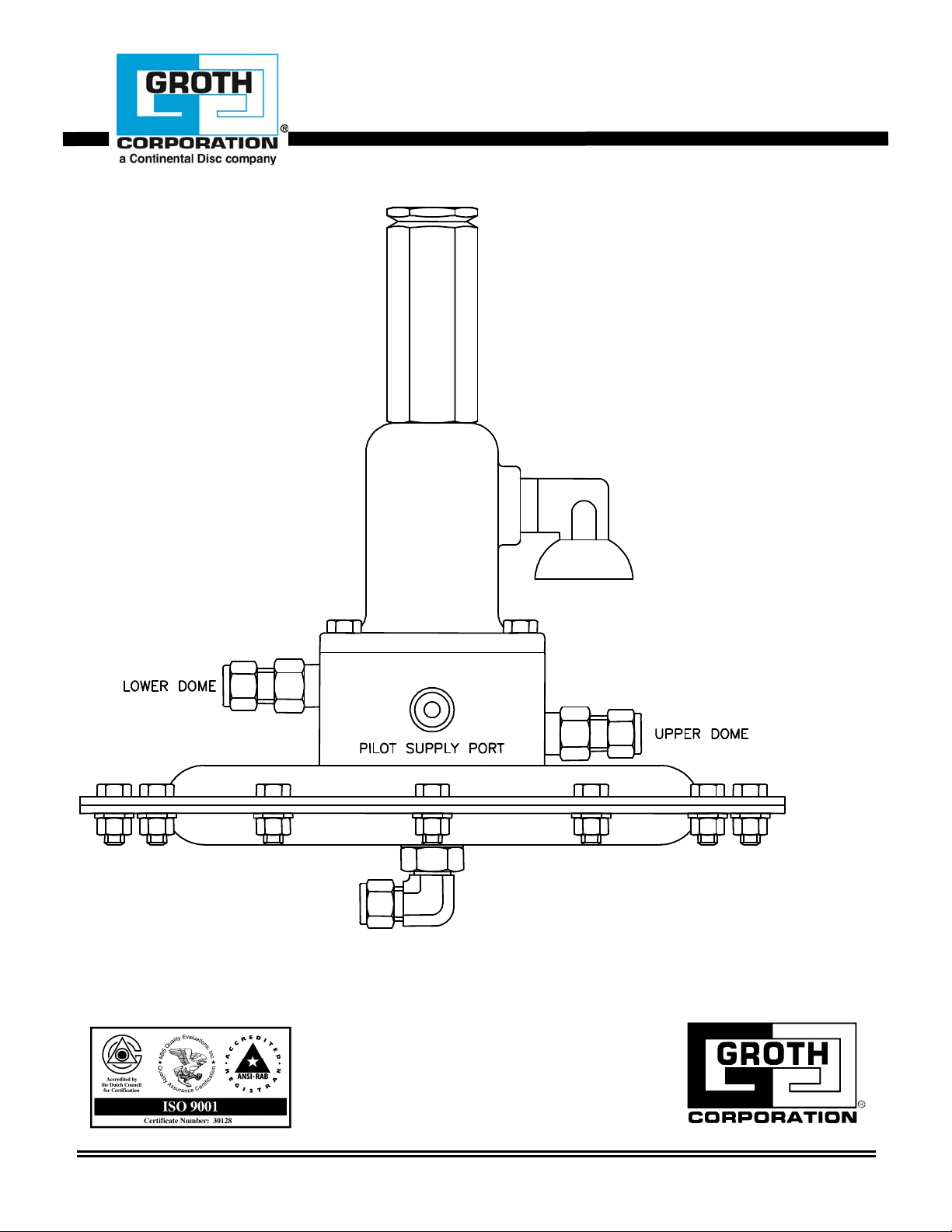
The “upper dome” port of the pilot is
connected to the upper dome or “push”
chamber of the actuator. The “lower
dome” port of the pilot is connected to the
lower dome or “pull” chamber of the
actuator.
When tank pressure is less than set
pressure, the pilot spool remains in the
lower position. Supply pressure is
applied to the upper dome of the valve
actuator and the lower dome is vented
through the pilot spring bonnet vent.
There is no emission from the pilot.
When tank pressure exceeds the set
pressure, the pilot spool moves to the
upper position. Supply pressure is
applied to the lower dome of the valve
Figure 1
1402revb.doc
1
Page 3

If the 1402 pilot is used to control a single
acting actuator, the “lower dome” port is
plugged and the pilot controls pressure to
the upper actuator chamber only.
The pilot must be maintained by a
knowledgeable valve technician. It
should only be assembled under clean
conditions, preferably in a shop
environment. Carefully read and
understand this manual before attempting
to adjust set pressure or repair the pilot.
For information not contained in this
manual, please contact:
Groth Corporation
13650 N. Promenade Blvd,
Stafford, TX, 77477
281-295-6800 (Phone)
281-295-6999 (Fax)
This manual is intended to provide
recommended procedures and practices
for installation, operation, and
maintenance of the Groth model 1402
pilot. Any standard procedures and
practices developed for a specific plant or
process should supersede this manual.
While this manual cannot cover all
possible contingencies, following these
guidelines should provide safe, reliable
valve performance.
SAFETY WARNINGS
This section is an overview of safety
guidelines that should be followed during
the installation, operation, and maintenance
of your valve. To understand the context of
these instructions and warnings, read and
understand this complete manual.
The purpose of a POV is to prevent
excessive pressure in a tank or process
system. The valve must be designed for the
proper MAWP and flow requirements of the
system. Consult API Standard 2000 for tank
protection sizing procedures. An
improperly specified or functioning relief
valve may result in structural damage to the
tank or system.
In the event of an actuator diaphragm
failure, the valve will vent pressure to the
atmosphere, causing the pressure relief
valve to fail in the OPEN position. The valve
will function like a weight loaded valve
under this condition and may require
additional over-pressure to provide rated
flow capacity. Consult factory for any
questions related to this over-pressure
condition.
POV relief pressure is set at the factory per
purchase order specifications. The set
pressure and range of adjustment are
stamped on the pilot valve nameplate. Do
not attempt to readjust the set pressure
beyond the limit specified on the
nameplate.
The pilot sense line is either 3/8" OD SS
tubing or larger. It must be open and
unobstructed to ensure that the pilot
"senses" actual tank pressure. For
applications where tank vapors may
condense or "solidify" in the sense tube or
pilot valve, a nitrogen purge may be
required to prevent internal obstruction.
Consult the factory for recommendations.
DO NOT attempt to remove the pilot valve
from the main valve without removing or
isolating the relief valve from the system.
ALTERNATIVE MEANS OF PRESSURE RELIEF
MUST BE PROVIDED WHEN THE VALVE IS
OUT OF SERVICE. After isolating the relief
valve, bleed all pressure from both main
and pilot valve before removing the valve.
Consult the pilot valve manual before
attempting to repair it. Both the pilot valve
and POV are exposed to process vapors.
Observe all plant procedures and Material
Safety Data Sheet recommendations for the
products in the system when inspecting,
adjusting or servicing the valves. Vents on
the body and spring bonnet of the pilot
valve must be clean and unobstructed for
proper and safe operation of the valve.
These vents should be inspected
periodically, and cleaned or replaced, if
necessary.
1402revb.doc
2
Page 4

Trouble Shooting
Any vapor emitted from the pilot should
be vented through the fitting [7] on the
spring bonnet.
There should be no emission when the
sensed tank pressure is less than 80% of
set pressure or greater than 110% of set
pressure.
The valve actuator upper dome should
receive tank pressure or vacuum or
independent supply pressure when the
sensed tank pressure is less than set
pressure. The lower dome should be
exposed to tank pressure when sensed
pressure is greater than 110% of set
pressure.
These conditions may be observed while
the valve is in service or during shop
testing. See test procedure on page 3. If
any of these conditions are not met, the
pilot must be disassembled, cleaned and
inspected. Replace all soft goods,
assemble and test according to the
following procedures.
Disassembly
Disconnect pilot at sense, upper dome and
lower dome ports. Remove tank pressure
supply tube. Invert the pilot and remove
hex bolts [22], lower actuator housing
[27], gasket [25], diaphragm [26] and
support plate sub-assembly. If the
diaphragm is damaged, it may be
replaced and the pilot may be tested
without further disassembly.
If further disassembly is required, remove
hex bolts [20] and upper actuator housing
[21].
Then invert pilot and remove the
adjustment screw cap [1], loosen the jam
nut [3], and back out the adjusting screw
[2] to release spring tension. Remove hex
bolts [8], the spring bonnet sub-assembly,
spring buttons [5 & 9], spring [6] and
retainer plate [10]. Remove the spool/seat
sub-assembly. This will require some
force to slide the O-Rings from the body.
Remove the upper and lower seat inserts
[13] from the spool [12]. Remove one
spool O-Ring [15], the seat [16] and the
other O-Ring [15]. Thoroughly clean and
inspect all parts. All seating surfaces
should be sharp but free of burrs or nicks.
Replace all O-Rings.
Note: Consult factory for soft goods kit
replacement for any valves sold prior
to March 2000.
Assembly
Lightly lubricate all O-Rings, removing
any excess lubricant. Slide the seat [16]
onto the spool [12] before installing the
final O-Ring [15]. Then position the seat
inserts and all O-Rings and slide the
spool/seat sub-assembly into the body.
Verify that the spool moves freely inside
the seats.
Position the retainer plate [10], the spring
[6] and spring buttons [5 & 9] and the
spring bonnet sub-assembly. Insert the
hex bolts and tighten uniformly. The thin
plate will be deformed as the bolts are
tightened, firmly clamping the seat inserts
in place. If necessary, remove the vent
fitting [7] to verify that the adjusting screw
is engaged with the upper spring button.
Final screw adjustment will be made after
assembly is complete.
Invert the pilot and position the support
plate sub-assembly, diaphragm [26],
gasket [25] and lower actuator housing
[27]. Insert the hex bolts [22], lock
washers [24] and nuts [23] and tighten
uniformly. Install tank pressure supply
tube. Test and adjust for set pressure
according to the following procedure.
Then tighten the jam nut [3] and replace
the cap [1].
Test Procedure
Connect the pilot as shown in figure 2.
Increase the tank pressure very slowly.
Adjust the set pressure adjustment screw
as required to maintain the following
conditions.
1402revb.doc
3
Page 5

At tank pressure less than 80% of set
pressure, upper dome pressure should be
about equal to tank pressure and the vent
should be bubble tight. Minimal leakage
may occur between 80% and 90% of set
pressure.
At set pressure, the upper dome pressure
should be less than 50% of set pressure
and the vent should be flowing freely.
At 110% of set pressure, the lower dome
pressure should be greater than 75% of
set pressure, the upper dome should be
less than 10% and the vent should show no
leakage. The vent should be bubble tight
above 110% of set pressure.
Figure 2
When all conditions have been met, install
the pilot on the valve by connecting the
tubing to the sense, upper dome and
lower dome ports. When pressure is
applied to the valve, test all connections
with a soap solution.
# DESCRIPTION MATL
1 Cap, Adjustment Screw 316
2 Screw, Adjustment 316
3 Nut, Jam 316
4 Bonnet, spring 316
5 Button, spring 316
6 Spring 316
7 Vent Aluminum
8 Bolt, hex 316
9 Button, spring 316
10 Plate, retainer 316
11 Body 316
12 Spool 316
13 Seat insert 316
O-Ring Elastomer
14
O-Ring Elastomer
15
16 Seat 316
17 Rod, actuator HDPE
18 Rivet, pop 316
19 Plate, diaphragm 316
20 Bolt, hex 316
21 Actuator housing, upper 316
22 Bolt, hex 316
23 Nut, hex 316
24 Washer, lock 316
Gasket FEP
25
Diaphragm FEP
26
27 Actuator housing, lower 316
28 Elbow, male 316
29 Washer, flat 316
O-Ring Elastomer
30
31 Connector, male 316
32 Nut, jam 316
33 Spacer, diaphragm Nylon
= Included in Soft Goods Kit
Elastomer Soft Goods Kit
Buna-N K1402BP
EPR K1402EP
FFKM K1402KP
Fluoropolymer K1402VP
1402revb.doc
4
Page 6

Figure 3
PRODUCT LIMITED WARRANTY
A. Seller warrants that products which are manufactured by
Seller, are manufactured in accordance with published
specifications and free from defects in materials and/or
workmanship for a period of (12) twelve months. Seller, at
its option, will repair or replace any products returned
intact to the factory, transportation charges prepaid, which
Seller, upon inspection, shall determine to be defective in
material and/or workmanship. The foregoing shall
constitute the sole remedy for any breach of Seller's
warranty.
B. THERE ARE NO UNDERSTANDINGS, AGREEMENTS,
REPRESENTATIONS, OR WARRANTIES, EXPRESS OR
IMPLIED, (INCLUDING MERCHANTABILITY OR FITNESS
FOR A PARTICULAR PURPOSE REGARDING PRODUCTS )
UNLESS SPECIFIED IN THE SALES CONTRACT . THIS
CONTRACT STATES THE ENTIRE OBLIGATION OF SELLER.
Seller makes no warranties, either express or implied,
except as provided herein, including without limitation
1402revb.doc
thereof, warranties as to marketability, merchantability, for a
particular purpose or use, or against infringement of any
patent of products. In no event shall Seller be liable for any
direct, incidental or consequential damages of any nature, or
losses or expenses resulting from any defective new product
or the use of any such product, including any damages for
loss of time, inconvenience, or loss of use of any such
product.
C. The original Manufacturer shall be solely responsible for the
design, development, supply, production, and performance
of its products hereunder, and the protection of its trade
name or names, if any. It assumes no responsibility, for
products modified or changed in any way by its agent or
customer. Any such modifications or changes to products
sold by Seller hereunder shall make the product limited
warranty null and void.
D. The Manufacturer shall be under no obligation to
manufacture, sell, or supply, or to continue to manufacture,
sell or supply any of the Products
5
 Loading...