

Page 1
Installation, Operation and Maintenance Manual for
Pilot Operated Valves
Models 1400, 1420, 1430, 1460
IOM1400.0
January 2, 2014
REV A 12393
REF. ID 98136
IOM1400.0
REV. A 12541
Page 2

TABLE OF CONTENTS
DESCRIPTION PAGE
Introduction
Pilot Valve Design and Function
Safety Warnings
Shipping, Inspection and Storage
Installation
Maintenance
Disassembly
Assembly
Figures and Tables
Troubleshooting Guide
Customer’s Notes
How to Order
Product Limited Warranty
LIST OF FIGURES
1. Tank Installation - Safety
Equipment
2. Groth Nameplate
3. Valve Port Identification
4. Available Seat Configurations
5. Model 1400
6. Model 1420
7. Model 1430
8. Model 1460
LIST OF TABLES
1. 1400 Series Pilot Operated Valve
Models
2. Body Flange Gasket Dimensions
3. Recommended Min. Torque Values
4. Notes for Figure 4 Thru Figure 7
5. Part no. for Vacuum Pallet Assy.
6. Lubricants – Specifications
7. Troubleshooting Guide
8. Abbreviations
NOTE:
For a list of abbreviations used in this manual, refer to Table 8.
1
3
3
4
4
5
5
6
6
12
13
14
14
2
2
6
7
8
9
10
11
2
4
4
6
7
12
12
12
INTRODUCTION
Pressure and/or vacuum relief valves are used
on liquid storage tanks and other process
vessels or systems to prevent structural damage
due to excess internal pressure or vacuum.
Storage tanks are pressurized when liquid is
pumped in, compressing the existing vapor or
when increasing temperature causes increased
evaporation or expansion of existing vapor.
Conversely, a vacuum may be created when
pumping out or due to decreasing temperature.
To prevent damage, vapor must be allowed to
escape or enter the tank at a specified pressure
or vacuum condition. The volume rate of
venting depends upon the tank size, volatility of
the contents, the pumping rate and the
temperature. See API Standard 2000 for the
procedures to determine venting requirements.
The pilot operated relief valve has two principal
advantages over other types of relief valves:
1) It is bubble tight to set pressure.
2) It achieves the full open position at 10%
above set pressure.
These characteristics permit operating
pressures nearer to the maximum allowable
working pressure of the tank. High operating
pressures reduce evaporation and total venting
volume, thereby reducing product loss and the
cost of processing emissions. A tank may also
have provisions for emergency pressure relief
due to fire exposure and/or inert gas blanketing
of the vapor space. A typical tank installation is
shown in Figure 1 which includes a 1400 Pilot
Operated Pressure/Vacuum Relief Valve, a Gas
Blanketing Regulator (Model 3011) and a 2500
Emergency Pressure Relief Valve which
provides protection under fire or other abnormal
conditions. Groth Corporation manufactures all
of these devices.
A Pilot Operated Valve (POV) must be carefully
maintained by a qualified valve technician. It
should only be assembled under clean
conditions, preferably in a service shop
environment. Carefully read and understand
this manual before attempting to repair a 1400
series POV. Groth Corporation provides repair
services for all products manufactured by the
Groth Products Group.
.
1
Page 3
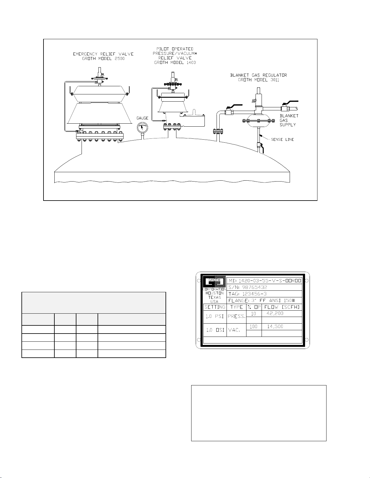
FIGURE 1: TANK INSTALLATION - SAFETY EQUIPMENT
*Pressure relief is pilot operated, vacuum relief is weight loaded.
The 1400 Series Pilot Operated Valves are
designed to provide pressure and/or vacuum
relief for API 620 and 650 tanks. Several
configurations are available; these are
summarized in Table 1 below. Each type is
available with either a standard FEP film or with
an O-Ring pallet. A variety of material options
are available depending on the type of service.
TABLE 1 : 1400 SERIES MODELS
(Pilot Operated Pressure Valves)
Model P V Vacuum Operation
1400
1420
1430
1460
The 1420 and 1460 POV are designed to be
used in header systems where the vapors are
piped away to a vapor recovery unit. The 1400
and 1430 POV’s vent to atmosphere.
Weight Loaded
Weight Loaded
Not Available
Not Available
The nameplate below shows the basic
information that is listed on each relief valve:
FIGURE 2: GROTH NAMEPLATE
For more information about these valves,
please contact:
Groth Corporation
13650 N. Promenade Blvd,
Stafford, Texas 77477
281-295-6800 (phone)
281-295-6995 (fax)
2
Page 4

PILOT VALVE DESIGN AND
FUNCTION
Each application must be reviewed to ensure
material compatibility of all metal and soft good
components with the service conditions. The
pallet assembly and wetted components are
available in Aluminum or 316 SS; they may be
upgraded to Alloy C276 or other alloys for
severe corrosive service. Diaphragms are all
FEP film; other soft goods can be specified as
Buna-N, FKM, or FFKM. The standard sense
tubing is 316 SS; it is available in PVDF for
severe corrosive chemicals.
The pilot valve is set at the factory to comply
with the specification on the purchase order.
The range of adjustment will depend on the
spring installed and will be stamped on the
nameplate. The pressure setting may be
SAFETY WARNINGS
This section is an overview of safety guidelines
that should be followed during the installation,
operation, and maintenance of your valve. To
understand the context of these instructions and
warnings, read and understand this complete
manual.
The purpose of a POV is to prevent excessive
pressure in a tank or process system. The valve
must be designed for the proper MAWP and flow
requirements of the system. Consult API
Standard 2000 for tank protection sizing
procedures. An improperly specified or
functioning relief valve may result in structural
damage to the tank or system.
In the event of an actuator diaphragm failure, the
valve will vent pressure to the atmosphere,
causing the pressure relief valve to fail in the
OPEN position. The valve will function like a
weight loaded valve under this condition with a
lower setting point, and will normally provide
rated flow capacity. Consult factory for any
questions related to this over-pressure condition.
POV relief pressure and blowdown are set at the
factory per purchase order specifications.
The set pressure and range of adjustability are
stamped on the pilot valve nameplate. DO NOT
attempt to readjust the set pressure beyond the
limit specified on the nameplate.
changed within the design range either while on
line or in a service shop. Observe the proper
setting and testing procedure in the appropriate
pilot valve manual.
This manual is intended to provide
recommended procedures and practices for
installation, operation, and maintenance of the
Groth Series 1400 Pilot Operated Valve (POV)
Series. Any standard procedures and practices
developed for a specific plant or process may
supersede this manual. Although this manual
cannot cover all possible contingencies,
following these guidelines should provide safe,
reliable pilot valve performance.
Note: This manual covers the operation and
maintenance of only the main valve; refer to the
appropriate manual for the pilot valve
instructions.
The pilot sense line is either 3/8" OD SS tubing,
or 1/2" NPT PVDF pipe. It must be kept open
and unobstructed to ensure that the pilot
"senses" actual tank pressure. For applications
where tank vapors may condense or
"polymerize" in the sense tube or pilot valve, a
nitrogen purge may be required to prevent
internal obstruction of the tube. Consult the
factory for recommendations.
DO NOT attempt to remove the pilot valve from
the main valve without removing or isolating the
relief valve from the system. ALTERNATIVE
MEANS OF PRESSURE RELIEF MUST BE
PROVIDED WHEN THE VALVE IS OUT OF
SERVICE. After isolating the relief valve, bleed
all pressure from both main and pilot valve
before removing the valve. Consult the pilot
valve manual before attempting to repair it. Both
the pilot valve and POV are exposed to process
vapors. Observe all plant procedures and
Material Safety Data Sheet recommendations
for the products in the system when inspecting,
adjusting or servicing the valves. Vents on the
body and spring bonnet of the pilot valve must
be clean and unobstructed for proper and safe
operation of the valve. These vents should be
inspected periodically, and cleaned or replaced,
if necessary.
3
Page 5
SHIPPING, INSPECTION AND
STORAGE
The POV is packed and supported to prevent
damage or contamination during shipping. It
should be similarly protected during subsequent
handling and storage. Always keep all ports
plugged to prevent intrusion of foreign materials.
Inspect the valve for any sign of damage that
may have occurred in shipment and report this
to the carrier. If there are indications of physical
damage or internal contamination, the valve
must be disassembled, cleaned and inspected
before installation. The spring adjustment cap
and blowdown screw locknut will be "car sealed"
to ensure that the factory pressure setting has
not been altered.
Inspect the valve for any sign of damage that
may have occurred in shipment and report this
to the carrier and Groth Corporation.
Lifting eyes are provided on the upper actuator
for handling the valve. To avoid damage to the
lower flange surface, set the valve on a soft
clean gasket material until it is ready to be
installed. It should be stored in a clean
environment until it is to be mounted on the tank.
The pilot pickup fitting is in the body and must
be kept completely free of all foreign materials.
DO NOT store the valve directly on the ground.
INSTALLATION
The 1400 Series valves are precision devices
that must be handled carefully to ensure seat
tightness.
1. At installation, the valve should be smoothly
lifted into position using the lifting eyes on
the actuator. Use the actuator housing to
align the valve directly over the tank nozzle.
Do NOT use the pilot valve or pickup line to
pull the valve into position.
2. Aluminum valve bodies should be
connected with flat faced 150# ANSI
flanges. A full faced gasket is
recommended. Mating flanges should be
flat within .020" and clean, free of scratches,
corrosion and tool marks.
3. Each valve is leak tested at the factory as
part of our standard inspection procedures.
4. Inspect the gasket; make sure that the
material is suitable for the service. Gasket
dimensions are listed below, Table 2. Full
gaskets must be used with flat face flanges.
Either full or ring gaskets may be used with
raised face flanges.
Table 2
Body Flange Gasket Dimensions
150# ANSI
Flange*
2” RF 4.12 2.38 --- --- --3” RF 5.38 3.50 --- --- --4" RF 6.88 4.50 --- --- --6” RF 8.75 6.62 --- --- ---
8” RF 11.00 8.62 --- --- --10” RF 13.38 10.80 --- --- --12” RF 16.12 12.80 --- --- ---
2" FF 6.00 2.00 4.75 0.75 4
3" FF 7.50 3.00 6.00 0.75 4
4” FF 9.00 4.00 7.50 0.75 8
6” FF 11.00 6.00 9.50 0.88 8
8” FF 13.50 8.00 11.75 0.88 8
10” FF 16.00 10.0 14.25 1.00 12
12” FF 19.00 12.0 17.00 1.00 12
* RF = Raised Face, FF = Flat Face
O.D.
(IN)
I.D.
(IN)
B.C.
(IN)
Hole
(IN)
Qty
5. Lubricate all studs and nuts with an
appropriate thread lubricant. If stainless
steel fasteners are used, use an anti-seize
lubricant such as moly-disulfide (Table 6).
6. Center the gasket within the bolt circle of
the tank nozzle flange.
7. Set the valve carefully on the nozzle.
8. Install nuts and lock-washers and torque all
fasteners to half the recommended value in
a staggered, alternating pattern. Consult
with Plant and/or Maintenance Personnel
for appropriate practices and standards.
Table 3
Recommended Minimum Torque Values*
Size
10” 12 7/ 8” - 9 75 138
12” 12 7/ 8” - 9 93 179
*Note: Torque values are based on a gasket factor m = 3.5,
gasket factor y = 4000 psi, operating pressure = 30 psi
Qty
Holes
2” 4 5/ 8” - 11 31 81
3” 4 5/ 8” - 11 43 106
4” 8 5/ 8” - 11 29 68
6” 8 3/ 4” - 10 51 101
8” 8 3/ 4” - 10 78 142
Bolt
(UNC)
Torque (lb-ft)
Raised Face Flat Face
9. Make sure that the flanges are not distorted
and that the gasket is evenly compressed.
10. Make up the final torque and check that no
further nut rotation occurs.
11. Normally, the pilot sense is integral to the
valve assembly. However, if the optional
4
Page 6

remote sense connection is specified, an
external sense line must be installed. See
the appropriate manual or attached tag for
recommendations. If the valve utilizes a
1402 Pilot Valve, there will be two
connections to the tank. The connections
can only be combined (with a tee) at the
tank connection.
4. Body - nozzle flange joint gasket
Refer to the troubleshooting section of this
manual or the pilot valve manual for probable
causes for these type of problems.
The main and pilot valve actuator housings,
valve bodies, pallet assemblies and other
components are exposed to the process vapor.
MAINTENANCE
Safety Warning
If the valve must be removed from the tank for
any reason, make sure that all pressure has
been released before the flange fasteners are
loosened. Refer to your company procedures
before venting the tank pressure and when
handling toxic or otherwise hazardous materials.
Observe all standard safety precautions as
specified on Material Safety Data Sheets for the
product(s) in the system while removing the
valve and when repairing it.
The 1460 POV does not require routine
lubrication or adjustments. It should be checked
periodically, at least twice a year, to confirm that
the valve is functioning properly and that the set
point is correct. Test connections can be
provided to facilitate testing the valve in the field.
The pilot valve is designed to function in a failsafe manner. The failure of a seal or diaphragm
will cause pressure to be vented to the
atmosphere; the resulting loss in pressure will
cause the main valve to open under rising
pressure.
Periodic inspection for seat tightness should be
done to ensure compliance with local air
pollution control requirements. If the valve
relieves to the atmosphere, this may
accomplished with a gas detector calibrated for
the principle product in the system.
The valve will need to be periodically removed
from the tank for inspection of diaphragms,
gaskets and seals. When this is done, the valve
must be handled carefully using the lifting eyes
on the actuator housing.
Refer to handling instructions listed in the
Installation section of this manual.
If a vapor leak is detected, it will likely be from
one of the following sources:
1. Pilot valve
2. Main valve actuator
3. Main valve diaphragm
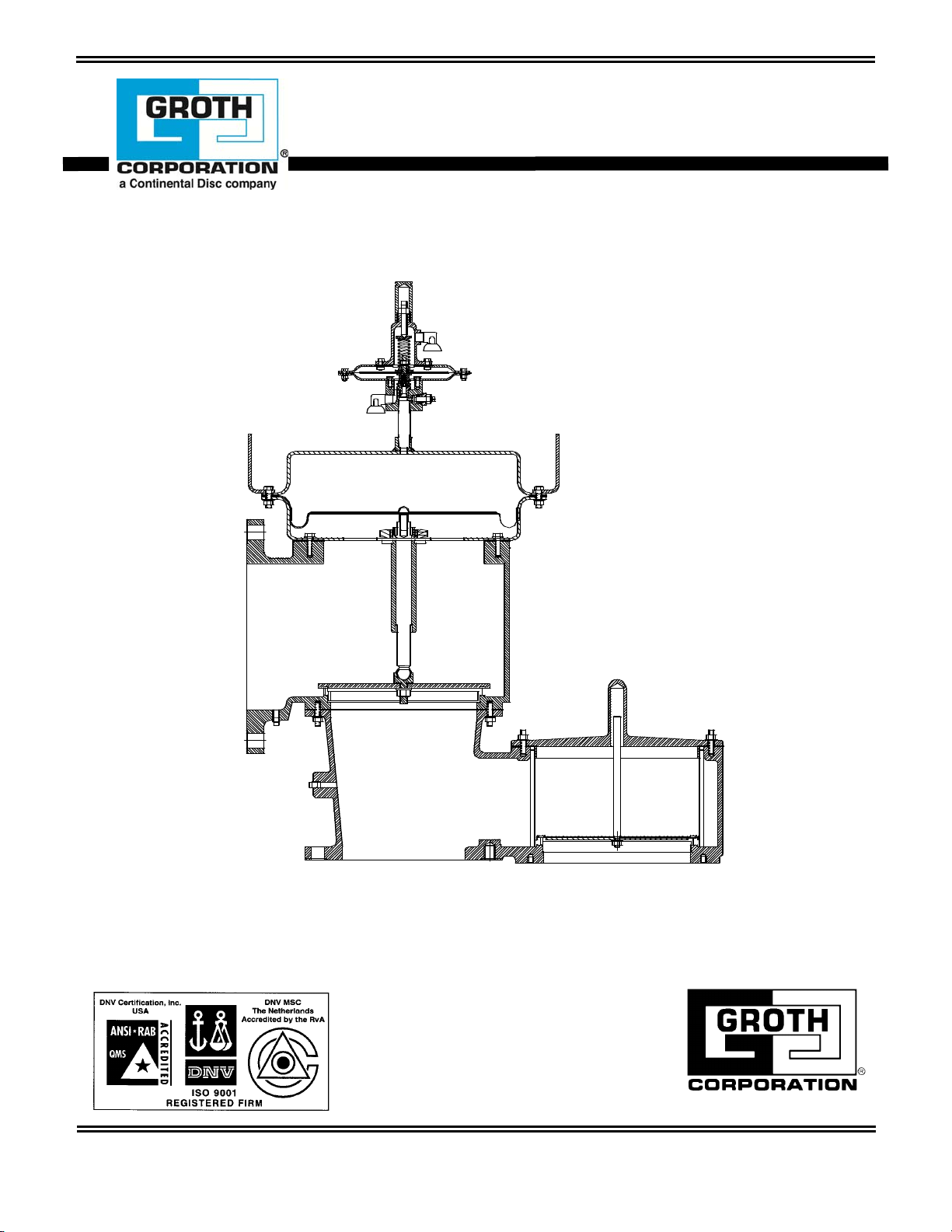
DISASSEMBLY
The 1400 series valves can be simplified into
three modules. These modules can be seen in
the figures below:
Weatherhood (with Pilot)
Outlet (with Pilot)
Vacuum (integral with body)
Before any disassembly or assembly, make sure
that there is NO PRESSURE (positive or
negative) in the system.
Outlet/ Weatherhood Disassembly
1. Disconnect the tubing connections (pilot to
main valve).
2. Remove the pilot valve. Refer to appropriate
pilot valve manual for disassembly
instructions.
3. Remove all fasteners holding the actuator
housings together.
4. Carefully lift the upper housing to avoid
damaging the actuator diaphragm.
5. Remove the housing gaskets.
6. Remove the actuator diaphragm and the
screw holding the support plate.
7. Remove the actuator support plate.
8. Remove the fasteners holding the lower
housing to the body (Models 1420 & 1460),
or weatherhood posts (Models 1400 &
1430).
9. Lift lower housing and stem guide assembly.
This assembly will slide over the stem.
10. Lift the stem and pallet assembly out of the
valve, invert it, and hold the stem in a soft
chuck vise (to avoid damage to the stem).
11. Remove the nut, to disassemble the pallet
assembly.
5
Page 7

Vacuum Disassembly
1. Remove the nuts from the cover.
2. Lift the cover.
3. Remove the gasket.
4. Lift the stem-pallet assembly. (Make note of
the weights. The valve must be
reassembled with the weights in the same
location to achieve the specified settings.)
5. Invert the assembly.
6. Remove the nut holding the assembly
together.
ASSEMBLY
Inspect all guides for corrosions, damage or
product build up. Also inspect the vacuum cover
guide bore. Check the metal seating surfaces
for pitting, corrosion or product build up. It is
recommended to replace ALL soft goods
including diaphragms, O-Rings and cover
gaskets. Note, the stem guide has internal
Fluoropolymer bushings.
TABLE 4 : NOTES FOR FIGURE 5 THROUGH FIGURE 8
NOTE DESCRIPTION
1 Pallet Diaphragms & O-Rings. These soft goods should be replaced each time the valve is
disassembled. Standard material options include FEP, Buna, FKM, & FFKM.
2 Gaskets: Non-Asbestos Fiber. These should be replaced each time the valve is
disassembled.
3 Bushing Guides: Fluoropolymer. At assembly, inspect stem travel through guides. The
stem should slide smoothly with minimal drag. Replace as required.
4 Actuator Diaphragms & Gaskets. Replace each time valve is disassembled they are
available only in FEP.
FIGURE 3: VALVE PORT IDENTIFICATION
If the seats are damaged they must be lapped
using a flat ground metal disc with fine grit
emery cloth attached and lapping compound.
Wipe the seating surface clean before assembly.
To assemble a valve, reverse the disassembly
procedure.
FIGURES AND TABLES
The following figures are to assist in identifying
components during disassembly and assembly
of the Groth 1400 Series valves. The actual
configurations might vary because of special
applications and customers’ request, but the
operation and function is similar.
Figure 5 through Figure 8 include a NOTE
column. For an explanation of the NOTES, see
Table 4 below.
For Lubricants suggested, see Table 6.
For Troubleshooting Guide, see Table 7.
For Abbreviations, see Table 8.
6
Page 8

ITEM DESCRIPTION
1 Pallet*
2 Seat**
3
Diaphragm (Fig 4.1)
O-ring (Fig 4.2)
FIGURE 4 : AVAILABLE SEAT CONFIGURATIONS
FIGURE 4: AVAILABLE SEAT CONFIGURATIONS
Fig. 4.1 Fig 4.2
* Actual pallet may not resemble drawing. Pallet design varies with operation.
** Seat can be integral (machined into body), or a ring insert. (Depends on the body material).
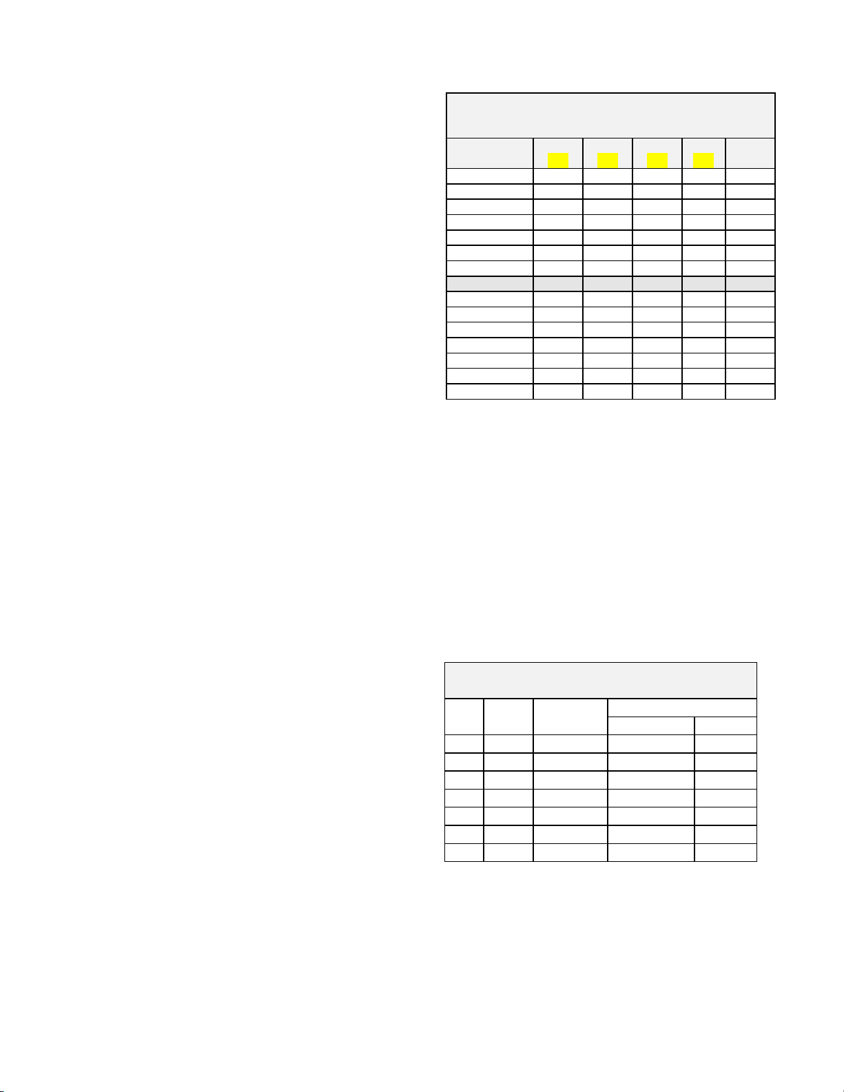
TABLE 5 : PART NUMBERS FOR VACUUM PALLET ASSEMBLIES
Component
2" 3" 4" 6" 8" 10" 12"
FEP Diaphragm, 10 mil
FEP Diaphragm, 20 mil
Gasket, Outlet (bottom)
Gasket, Cover (top)
O-Ring (plate pallet) -FKM
Setting < 4 OSI 4 - 8 OSI 8 - 12 OSI 12 - 16 OSI
Diaphragm 10 mil 20 mil 10 mil 20 mil 10 mil 20 mil 10 mil 20 mil
Quantity 1 --- --- 1 1 1 --- 2
80040162 80040362 80040562 80040762 80040962 80041162 80041362
80040154 80040357 80040568 80040761 80040963 80041167 80041354
80040159 80040359 80040559 80040759 80040959 80041159 80041359
80040158 80040358 80040558 80040758 80040958 80041158 80041358
89107010 ( #010 70 durometer) 89107012 ( #012 70 durometer)
Valve Size
* Please provide the valve serial number and pressure/vacuum settings when ordering replacement parts.
FIGURE 5: MODEL 1400
7
Page 9

ITEM DESCRIPTION NOTE
1 Pilot Valve Assembly
2 Pipe Nipple
3 Upper Diaphragm Case
4 Lifting Eye
5 Gasket – Actuator 4
6 Hex Bolt
7 Hex Nut
8 Lock Washer
9 Weatherhood
10 Cover – Vacuum
11 Lock Washer
12 Hex Nut
13 Stud
14 Gasket – Cover 2
15 Body
16 Guide Rod – Vacuum
17 Pallet – Vacuum
18 Retainer Plate – Vacuum
19 Diaphragm – Vacuum 1
20 Stem – Vacuum
21 Hex Nut
22 Lock Washer
23 Tubing
24 Male Connector
ITEM DESCRIPTION NOTE
25 Connector
26 Weatherhood Post
27 Lock Washer
28 Hex Nut
29 Pallet – Pressure
30 Diaphragm, Pressure Pallet 1
31 Retainer Plate – Pressure
32 Swivel Fitting
33 Belleville Washer
34 Hex Nut
35 Seal - Guides 1
36 Stem Guide
37 Washer – Stem Guide
38 Hex Jam Nut
39 Bushing 3
40 Set Screw
41 Stem – Pressure
42 Screw
43 Support Plate
44 Diaphragm 4
45 Screen
46 Lower Diaphragm Case
47 Male Connector
8
Page 10

FIGURE 6: MODEL 1420
ITEM DESCRIPTION NOTE
1 Pilot Valve Assembly
2 Pipe Nipple
3 Button Head Cap Screw
4 Lifting Eye
5 Support Plate
6 Diaphragm, Actuator 4
7 Hex Bolt
8 Lock Washer
9 Set Screw
10 Outlet
11 Stem Guide
12 Bushing 3
13 Swivel Fitting
14 Pallet
15 Gasket 2
16 Vent – Cover
17 Stud
18 Lock Washer
19 Hex Nut
20 Gasket 2
21 Guide Rod
22 Stem
23 Body
24 Diaphragm – Vacuum Pallet 1
25 Retainer Plate
26 Seat Ring
27 Lock Washer
ITEM DESCRIPTION NOTE
28 Hex Nut
29 Pallet
30 Seat Ring
31 Retainer Plate
32 Hex Nut
33 Belleville Washer
34 Male Connector
35 Stud
36 Hex Nut
37 Lock Washer
38 Union Connector
39 Tubing
40 Drain Plug
41 Diaphragm, Pressure Pallet 1
42 Seal 1
43 Stem
44 Washer
45 Gasket 2
46 Lower Diaphragm Case
47 Gasket, Actuator 4
48 Hex Bolt
49 Hex Nut
50 Lock Washer
51 Upper Diaphragm Case
52 Hex Jam Nut
53 Male Connector
9
Page 11

FIGURE 7: MODEL 1430
ITEM DESCRIPTION NOTE
1 Pilot Valve Assembly
2 Male Connector
3 Pipe Nipple
4 Cap Screw
5 Support Plate
6 Hex Jam Nut
7 Stem Guide
8 Screen
9 Seal – Swivel Guide 1
10 Swivel Fitting
11 Tubing
12 Union Connector
13 Male Connector
14 Pick – up Fitting
15 Belleville Washer
16 Hex Nut – Swivel
17 Inlet
18 Weatherhood Post
19 Lock Washer
ITEM DESCRIPTION NOTE
20 Hex Nut
21 Seat Ring
22 Pallet
23 Diaphragm, Pressure Pallet 1
24 Retainer Plate
25 Stem
26 Bushing – Stem Guide 3
27 Weatherhood
28 Washer – Stem Guide
29 Lower Actuator Housing
30 Hex Bolt
31 Lock Washer
32 Hex Nut
33 Diaphragm – Actuator 4
34 Gasket – Actuator 4
35 Lifting Lug
36 Upper Actuator Housing
37 Set Screw
10
Page 12

FIGURE 8 : MODEL 1460
ITEM DESCRIPTION NOTE
1 Pilot Valve Assembly
2 Male Connector
3 Pipe Nipple
4 Lifting Eye
5 Cap Screw
6 Support Plate
7 Diaphragm, Actuator 4
8 Hex Bolt
9 Lock Washer
10 Set Screw
11 Stem Guide
12 Bushing – Guides 3
13 Swivel Fitting
14 Pallet - Pressure
15 Gasket 2
16 Lock Washer
17 Union Connector
18 Tubing
19 Male Connector
20 Hex Nut
ITEM DESCRIPTION NOTE
11
21 Belleville Washer
22 Inlet
23 Stud
24 Hex Nut
25 Drain Plug
26 Diaphragm, Pressure Pallet 1
27 Seal 1
28 Stem
29 Washer
30 Outlet
31 Gasket 2
32 Lower Diaphragm Case
33 Gasket 2
34 Hex Bolt
35 Hex Nut
36 Lock Washer
37 Upper Diaphragm Case
38 Hex Jam Nut
39 Bushing – Guides 3
Page 13

TABLE 6: LUBRICANTS – RECOMMENDATIONS
FASTENER LOCATION LUBRICANT – SEALANT MANUF. & PART NO.
Actuator Fastener Dry Moly Film Crown #6080 or equal
Stem Guide MS
Lubricant Fel-Pro [Loctite] #51048 or equal
2
Stem/Swivel Fitting Silicone Lubricant Dow Corning #33 or equal
Note: Lubricant selection must consider process environment.
TABLE 7: TROUBLESHOOTING GUIDE
PROBLEM INSPECTION SUGGESTED CORRECTIVE ACTION
Pilot Valve
Leak
Main Valve
Actuator Leak
Visual, audible or
vapor detector
Visual, audible or
vapor detector
Consult troubleshooting guide in specific pilot valve manual
Leakage at the actuator flange may be corrected by tightening
the fasteners adjacent to the leak path. If this is not successful,
it will be necessary to install a new gasket. Refer to
instructions on page 6.
Vapor leakage
from the valve
body outlet.
Visual, audible or
vapor detector
Leakage can occur at the valve body seat - FEP film interface;
other leak paths are the swivel seal or a torn actuator
diaphragm. After removing the upper actuator housing, lift the
pallet assembly off the seat and inspect for damage to the film
or foreign debris buildup on the seat or film. Clean or replace
the pallet diaphragm as required. Refer to page 6.
Vapor leakage
between the
valve body and
tank nozzle
Visual, audible or
vapor detector
Leakage between the flanges may be corrected by tightening
the fasteners. Follow mounting instructions listed on page 4.
The gasket may have deteriorated due to the chemical
environment; replace if required. The tank nozzle may be
warped, corroded or scratched. This will require resurfacing of
the flange face; note that a flat faced flange is recommended to
avoid potential damage to an aluminum valve body.
TABLE 8: ABBREVIATIONS
ANSI American National Standards Institute NPT National Pipe Thread
API American Petroleum Institute POV Pilot Operated Valve
BOM Bill of Materials PSIG Pounds/Sq. Inch – Gauge
DPHGM Diaphragm PTFE Fluoropolymer
FEP Fluorocarbon Film (Fluoropolymer) SS Stainless Steel
MAWP Maximum Allowable Working Pressure WC Water Column
MS2 Moly – Disulfide
12
Page 14

The nameplate on the Groth Series 1400 Pilot Operated Valve contains the model number, serial
number, set pressure and flow capacity. The model number contains additional information about
materials of construction and options. The following chart will assist in relating the model number to the
specifications of your pilot operated valve:
Notes:
Include model number when ordering
For special options, consult factory.
EXAMPLE 1 4 6 0 - 0 6 - 3 1 - V - S - OORO
Indicates a 6" Model 1460 with Carbon Steel body, Standard Trim using FKM soft goods with remote pilot pickup and
no specials.
PRODUCT LIMITED WARRANTY
A. Seller warrants that products which are manufactured by Seller, are manufactured in accordance with published specifications and free
from defects in material and/or workmanship for a period of (12) twelve months. Seller, at its option, will repair or replace any product
returned intact to the factory, transportation charges prepaid, which Seller, upon inspection shall determine to be defective in material
and/or workmanship. The foregoing shall constitute the sole remedy for any breach of Seller's warranty.
B. THERE ARE NO UNDERSTANDINGS, AGREEMENTS, REPRESENTATIONS, OR WARRANTIES, EXPRESS OR IMPLIED (INCLUDING
MERCHANTABILITY OR FITNESS FOR A PARTICULAR PURPOSE REGARDING PRODUCTS) UNLESS SPECIFIED IN THE SALES
CONTRACT. THIS CONTRACT STATES THE ENTIRE OBLIGATION OF SELLER.
Seller makes no warranties, either express or implied, except as provided herein, including without limitation thereof, warranties as to
marketability, merchantability, for a particular purpose or use, or against infringement of any patent of products. In no event shall Seller be
liable for any direct, incidental or consequential damages of any nature, or losses or expenses resulting from any defective new product or
the use of any such product, including any damages for loss of time, inconvenience, or loss of use of any such product.
C. The original Manufacturer shall be solely responsible for the design, development, supply, production, and performance of its products
hereunder, and the protection of its trade name or names, if any. It assumes no responsibility, for product modified or changed in any way
by its agent or customer. Any such modifications or changes to products sold by Seller hereunder shall make the product limited warranty
null and void.
D. The Manufacturer shall be under no obligation to manufacture, sell, or supply, or to continue to manufacture, sell or supply any of the
Products.
13
 Loading...