

Grote 522 Equipment Manual

GROTE COMPANY
1160 Gahanna Parkway
Columbus, Ohio 43230
Telephone 614-868-8414 Fax 614-863-1647
www.grotecompany.com
DISCLAIMER
5/2/2011
Dear Customer,
The Grote Equipment Manual supplied to you is for the used equipment listed below. It is a copy
of the original manual which was correct and complete to contemporary standards at the time the
machine was released in factory "new" condition. Any modifications to the equipment since it left
Grote Service oversight, or performed without our knowledge, may not be included in the manual.
The Grote Company makes no warranty of any kind concerning the material contained within this
manual.
In addition, parts listed may now be obsolete since the time the manual was released. When
ordering parts by Grote part number, our Customer Service representatives will be able to alert
you if a part is obsolete. They may not be able to advise you if the part will be usable in the
current configuration of the machine. Grote Customer Service and Engineering will be happy to
assist you in determining which parts will work. Adequate detailed information regarding the
current state of your machine should be provided through photographs, drawing mark-ups, etc.
The design of the machine, as well as the information provided in the manual regarding safety
and sanitation guidelines, were complete and appropriate to industry standards at the time of the
original sale of the equipment. Please have your company's regulatory bodies examine the
machine for safety and sanitation compliance to current industry standards.
Equipment List
Slicer/Applicator
Model: 522 Serial Number: 1065029
Regards,
The Grote Company
1-888-534-7683

Equipment Manual
Slicer/Applicator
Model: 522
Serial No: 1065029
PRECISION SLICING AND APPLICATION SYSTEMS

Grote Service Manual
Slicer/Applicator
Hydraulic and All-Electric Models
__________________________
Installation Date
SS-10.DOC:1/26/2007 11:08 AM
1

ATTENTION
Do not attempt to operate this machine without first installing it correctly.
The customer is responsible for the proper operation of the machine and for following proper safety
standards when operating it.
The J. E. Grote Company, Inc. is not responsible for product contamination due to improper use,
improper sanitation, or part failure.
The J. E. Grote Company, Inc. reserves the right to make design or operational changes that may
not be included in this manual.
The J. E. Grote Company, Inc. makes no warranty of any kind concerning the material contained
within this manual and is not liable for errors, omissions, or incidental or consequential damages in
connection with the use of this manual.
WARRANTY
This J. E. Grote, Inc. machine is warranted to be free from defects in materials and workmanship
for a period of six (6) months. The warranty applies under normal use and service. The warranty
period begins the date of complete installation or thirty (30) days after the date of delivery,
whichever comes first. Shipping and installation costs of warranty parts are the expense of the
customer.
Copyright 1998 J. E. Grote Company, Inc.
PARTS AND SERVICE
J. E. GROTE COMPANY, Inc.
CORPORATE HEADQUARTERS • 1160 Gahanna Parkway, Blacklick, Ohio 43004 • Tel: 614-868-8414 • Fax 614-863-1647
Parts and Service (Toll Free within USA) • Tel: 1-888-53-GROTE (534-7683) • Fax: 1-888-39-GROTE (394-7683)
E-mail: service@grote.company.com sales@grotecompany.com
EUROPEAN SALES/SERVICE • Wrexham Technology Park, Wrexham, North Wales LL137YP, United Kingdom
Tel: Int +44 (0) 1978-362243 • Fax: Int +44 (0) 1978-362255
E-Mail: service@intl.grotecompany.com sales@intl.grotecompany.com
SS-10.DOC:1/26/2007 11:08 AM
2

Table of Contents
Information in the text section of this manual applies to all machines of this type unless
otherwise noted. The Operator Interface Information (when provided), Spare Parts List and
Drawings apply to the specific machine identified on the front cover.
OPERATION INFORMATION
Operating information is typically provided by Grote Service Personnel when a
machine is installed. On some machines this manual includes additional specific
information about the Operator Interface. When this information is provided it is in
the Operator Interface section near the end of the manual.
Maintenance and adjustments...........................................................................5
Manual Covers Both Hydraulic and All-Electric Slicers ...............................5
Hydraulic Power System.......................................................................5
All-Electric Power System.....................................................................5
Safety Cabinetry..........................................................................................5
Lubrication – All Electric Slicers ..................................................................5
Lubrication - Hydraulic Slicers.....................................................................5
Self-contained Hydraulic Power System...............................................5
Adding Hydraulic Fluid....................................................................5
Blade Scraper - All-Electric Slicers..............................................................5
Blade Scraper - Hydraulic Slicers................................................................5
Blade Guide Maintenance...........................................................................5
Blade Guide Maintenance Tools...........................................................5
Slot Scraper....................................................................................5
Slot Width Checking Tool...............................................................5
Slot Depth Checking Tool...............................................................5
Blade Guide Adjustment..............................................................................5
(Opt) Quick Disc Blade Guide Adjustment - All-Electric Slicers............5
(Opt) Removing the Quick Disc Blade Guide - All-Electric Slicers ..............5
(Opt) Reinstalling the Quick Disc Blade Guide - All-Electric Slicers............5
(Opt) Installing a New Quick Disc Blade Guide - All-Electric Slicers ...........5
Blade Motor Belt Drive - Hydraulic Slicers...................................................5
Product Holders...........................................................................................5
Height Adjustment.................................................................................5
Product Holder Height Adj - Hydraulic Slicers................................5
Product Holder Height Adj - All-Electric Slicers ..............................5
Alignment..............................................................................................5
Pivot Point - Hydraulic Slicers...............................................................5
SS-10.DOC:1/26/2007 11:08 AM
3

Slice Stroke Adjustment..............................................................................5
Stroke Length .......................................................................................5
(Opt) Two-Position Stroke Adjustment - All-Electric Slicers.................5
Stroke Starting Point.............................................................................5
Stroke Speed ..............................................................................................5
Changing the Thickness Range ..................................................................5
Slice Gap Adjustment - Hydraulic Slicers....................................................5
Slice Gap Adjustment - All-Electric Slicers..................................................5
Leveling the Thickness Tray........................................................................5
Pusher Bar Adjustment ...............................................................................5
Band Blade Installation................................................................................5
Blade Tracking ............................................................................................5
Idle Side Blade Tracking.......................................................................5
Drive Side Band Blade Tracking - Hydraulic Slicers .............................5
Drive Side Band Blade Tracking - All-Electric Slicers ...........................5
Bearing Replacement..................................................................................5
Drive Side Bearing Removal - Hydraulic Slicers ...................................5
Drive Side Bearing Replacement - Hydraulic Slicers............................5
Idle Side Bearing Removal - Non-sealed bearings - Hyd Slicers..........5
Idle Side Bearing Replacement - Non-sealed Bearings - Hyd Slicers...5
Clutch Maintenance.....................................................................................5
Clutch Coil Adjustment..........................................................................5
Clutch Coil Replacement ......................................................................5
Clutch Control Collar Adjustment..........................................................5
Tightening Proximity Switches.....................................................................5
Target Sensor..............................................................................................5
Banner Sensor......................................................................................5
Fiber Optic Sensor................................................................................5
Sensor Installation..........................................................................5
Teaching the Photoeye ..................................................................5
Resetting the Photoeye..................................................................5
Noise Characteristics - Hydraulic Slicers.....................................................5
Troubleshooting Charts...............................................................................5
Chart 1: Product Thickness Varies From Side To Side. ......................5
Chart 2: Product Thickness Varies From Front To Back......................5
Chart 3: Product Not Stacking Or Laying Down Properly.....................5
Chart 4: Excessive Product Scrap .......................................................5
Chart 5: Product Slinging.....................................................................5
Chart 6: Product Curling Or Twisting ...................................................5
Chart 7: Product Not Releasing Or Cutting Cleanly.............................5
SS-10.DOC:1/26/2007 11:08 AM
4

Chart 8: Rough Or Chafed Product.....................................................5
Chart 8: Rough Or Chafed Product......................................................5
Chart 9: Product Fracturing..................................................................5
Chart 10: Product Tailing.....................................................................5
Chart 11: Product Not Slicing Or Skipping...........................................5
Chart 12: Pump Won’t Run or Pump Pressure Low(Hyd Slicers).........5
Chart 13: Blade Won’t Run..................................................................5
Chart 14: Pendulum Won’t Move.........................................................5
Chart 15: Breaking Blades...................................................................5
Chart 16: Won’t Count Or Dead Space ...............................................5
Sanitation...........................................................................................................5
Recommended Cleaning Compound. .........................................................5
Guidelines for Cleaning...............................................................................5
Operator Interface Information...........................................................................5
Spare Parts List .................................................................................................5
Drawings............................................................................................................5
Note: Supplemental information may be inserted in the front cover pocket.
List of Figures
Figure 1. Typical Single-Head Hydraulic Slicer.......................................................................5
Figure 2. Typical Single-Head All-Electric Slicer (To Be Provided)........................................5
Figure 3. Grease Points ..........................................................................................................5
Figure 4. OSHA Material Safety Data Sheet for Hydraulic Oil - Pg 1..............................5
Figure 5. OSHA Material Safety Data Sheet for Hydraulic Oil - Pg 2..............................5
Figure 6. Blade Scraper - All Electric Machine........................................................................5
Figure 7. Blade scraper - Hydraulic Machines.........................................................................5
Figure 8. Blade Guide Maintenance Tools................................................................................5
Figure 9. Blade Guide................................................................................................................5
Figure 10. Quick Disconnect Blade Guide................................................................................5
Figure 11. Quick Disconnect Hold-Down Clamp......................................................................5
Figure 12. Correct Product Holder Height...............................................................................5
Figure 13. Product Holder Box Pivot Point - Hydraulic Machines..........................................5
Figure 14. Stroke Length Adjustment. .......................................................................................5
Figure 15. Slice Gap and Slice Thickness Adjustment Bolts - Hydraulic Machines.................5
Figure 16. Slice Gap..................................................................................................................5
Figure 17. Product Pusher - Hydraulic Machines ...................................................................5
Figure 18. Idle Side Tracking Adjustments(Non-Sealed Bearings)...........................................5
Figure 19. Clutch-Brake............................................................................................................5
Figure 20. Clutch Control Collar Adjustment...........................................................................5
SS-10.DOC:1/26/2007 11:08 AM
5
Slicer/Applicator
MAINTENANCE AND ADJUSTMENTS
This manual contains information about how to maintain, adjust, and clean the standard Grote
Slicer/Applicator. It does not include setup, control, and operational procedures.
Manual Covers Both Hydraulic and All-Electric Slicers
Grote slicers are built with two different types of power systems, Hydraulic and All-Electric. The
All-Electric slicer differs from the Hydraulic Slicer in several ways other than just the power system
of the machine. When a function being described differs with the type of slicer each type is
identified and described in this manual.
Hydraulic Power System
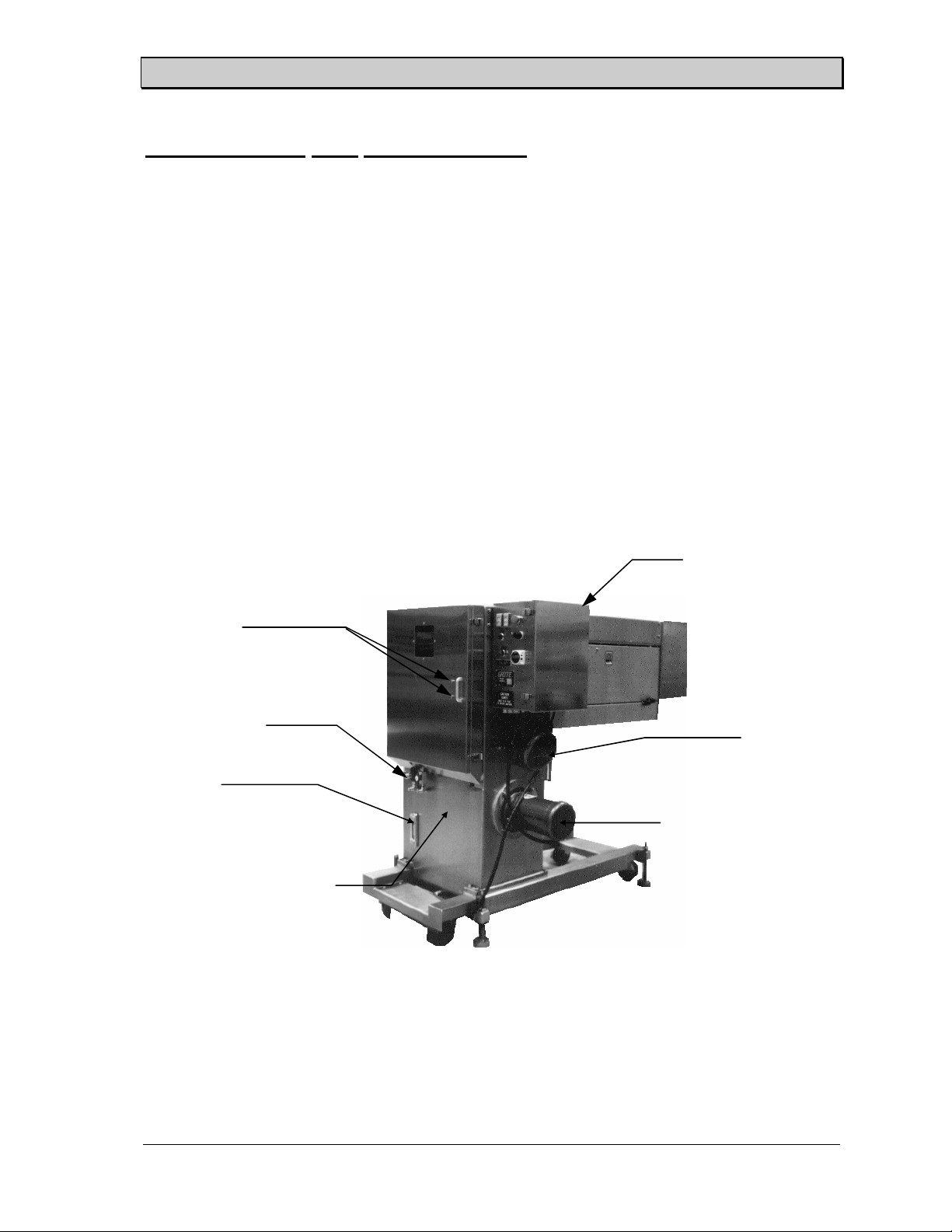
A built-in hydraulic power system drives the slicing heads. Slicing is controlled by hydraulic
valves that turn the hydraulic power on and off and set the speed of the slicing heads. A typical
single head hydraulic slicer is shown in Figure 1.
Electrical Control
Enclosure
Door Lock Bolts
Hydraulic Controls
Sightglass
Hydraulic Tank
Blade Drive Motor
Hydraulic Pump Motor
Figure 1. Typical Single-Head Hydraulic Slicer.
SS-10.DOC:1/26/2007 11:08 AM
Grote Company
6
Slicer/Applicator
Point
All-Electric Power System
The slicing heads are driven by an electric servo motor power system. Controls are all
electrical and controlled by a Programmed Logic Controller through an Operator Interface. A
typical single head all-electric slicer is shown in Figure 2.
Figure 2. Typical Single-Head All-Electric Slicer (To Be Provided).
Note: Both types of slicers are described in this manual. When a section applies to only one type
of system, it is identified in the section heading.
Safety Cabinetry
The cutting blade and drive mechanism for the blade are completely enclosed to provide maximum
safety for the operator. Access to the blade is easy with doors and removable covers.
Optionally provided proximity switches sense guard door closure and cut power to the slicer when
one of the doors is opened. The blade drive pulleys coast to a stop if they are running when a door
is opened.
Mechanically interlocked, defeat-proof safety switches are available as an option for guard doors.
These switches act as locks, preventing the doors from being opened until the machine has been shut
off and the blade drive pulleys have stopped rotating. The slicer must have power applied before
these switches will operate and allow the doors to be opened. A Safety Interlock Switch Locations
drawing included with the drawings at the end of the manual shows the location of the interlock
switches.
CAUTION: The safety cabinetry described above prevents an operator from gaining access to
the cutting blade from any position around the machine while the blade is running.
A conveying device under the slicer prevents the operator from access to the cutting
blade from beneath the machine. If the slicer is operated without a conveying
device in place, then steps must be taken to keep personnel from moving under the
slicer while it is operating.
Lubrication –
All Electric Slicers
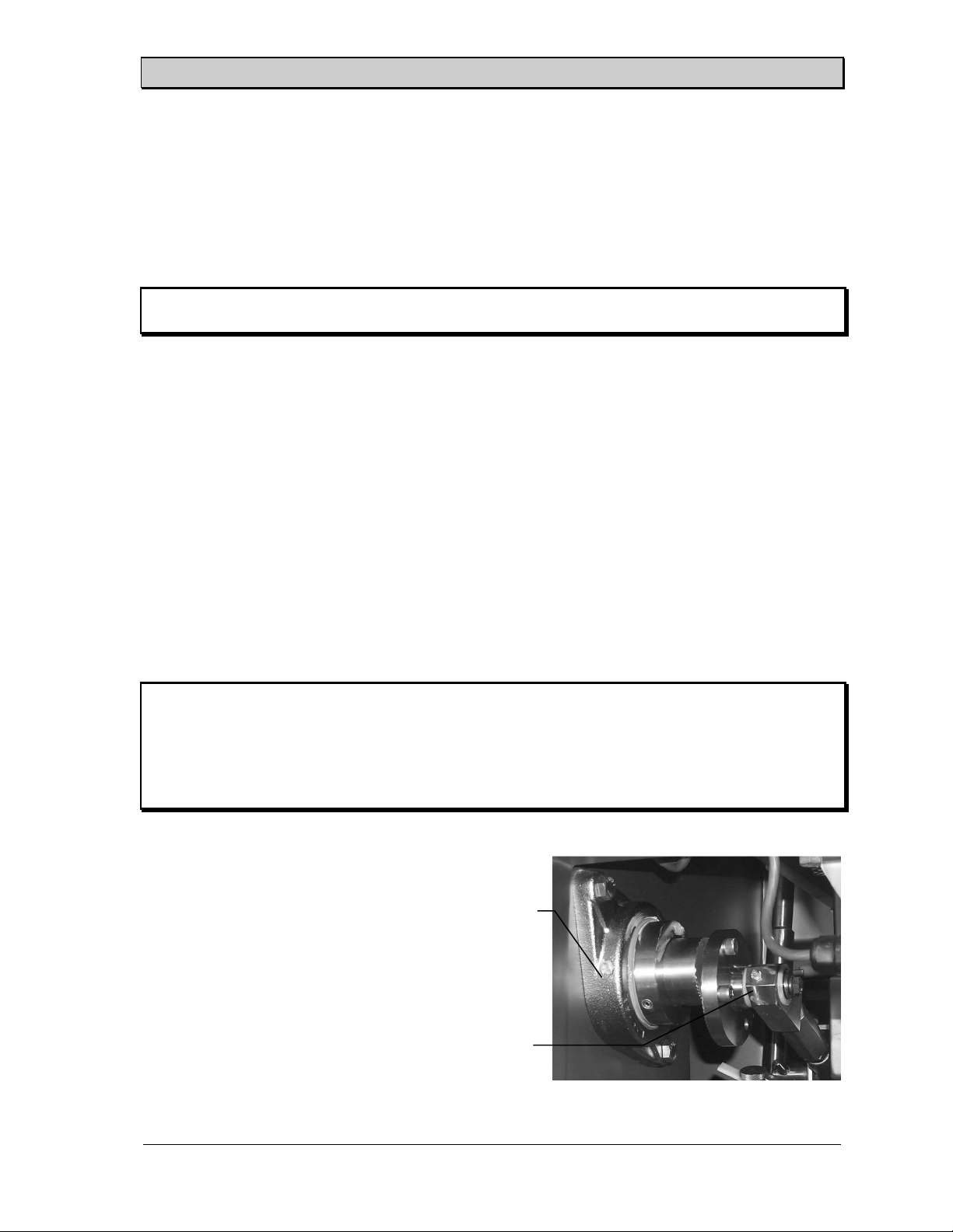
Each slicing head has two grease points.
One is on the end of the rod connecting the
offset crank to the cluster box and one is on
the crank bearing. Grease all fittings after
each washdown to purge excess water from
the bearings and increase component life.
Use FML-2 Lubriplate or equivalent USDA
approved grease.
SS-10.DOC:1/26/2007 11:08 AM
Grote Company
Crank
Bearing
Grease
Point
Connecting
Rod Grease
Figure 3. Grease Points
7

Slicer/Applicator
Lubrication -
Hydraulic Slicers
Grease the following bearings after each washdown of the equipment using FML-2 Lubriplate or
equivalent USDA approved grease. The remaining bearings should be greased weekly.
1. Drive side bearing block (Also grease the idle side bearing block on older machines that use
a non-sealed idle side bearing block).
2. Pivot rod ends (product holder box linkage).
3. Product holder box pivot point.
Check the condition of the bearings weekly and replace the bearings when any free movement is
detected. If movement is detected in the idle side drive pulley, replace the entire sealed bearing
assembly.
Self-contained Hydraulic Power System
NOTE: An OSHA Material Safety Data Sheet for the hydraulic oil is in Figure 4.
Some slicers are equipped with a built-in hydraulic power system. Hydraulic pump capacity is
typically six gpm with 60 hz electrical input or five gpm with 50 hz electrical input.
1. Check the reservoir oil level daily and keep it full using medium weight (SAE 10, SSU
213) hydraulic fluid. The black line indicates full and the red line indicates low. The
level should never fall below the red line.
2. Maintain the hydraulic system pressure at the normal operating pressure of 450 psig.
Never allow the machine to exceed 1000 psig.
3. Maximum operating temperature should not exceed 140 oF (60 oC).
4. Replace the return line oil filter cartridge after the first 50 hours of operation and every
300 hours thereafter. The oil filter is located inside the hydraulic tank.
Adding Hydraulic Fluid
Add medium weight fluid (SAE 10 or equivalent) if the level falls below the line in the
sight glass liquid level indicator.
1. Remove the tank cover.
2. Pour the hydraulic fluid through a 200 mesh or finer screen until the level
indicator reaches the line on the sight glass.
3. Replace the tank cover and tighten the nuts that hold it in place.
SS-10.DOC:1/26/2007 11:08 AM
Grote Company
8

Slicer/Applicator
Material Safety Data Sheet U.S. Department of Labor
May be used to comply with OSHA’s Hazard Occupational Safety and Health Administration
Communication Standard, 29 CFR 1910.1200. (Non-Mandatory Form)
Standard must be consulted for specific requirements. Form Approved OMB No. 1218-0072
IDENTITY (As Used on Label and List)
TPR-19
Section 1
Manufacturer’s Name
NATIONAL OIL PRODUCTS
Address (Number, Street, City, State, and ZIP Code)
1000 FOREST AVENUE
HAMILTON, OHIO 45015
Section II – Hazardous Ingredients/Identity Information
Other Units
Hazardous Components (Specific Chemical Identity; Common Name(s)) OSHA PEL ACGIH TLV Recommended % (optional)
SOLVENT REFINED PARAFFINIC PETROLEUM OIL
BY DEFINITION IN OSHA STANDARD 29 CFR 1900.1200,
THIS PRODUCT CONTAINS NO INGREDIENTS CLASSIFIED
AS HAZARDOUS.
Section III – Physical/Chemical Characteristics
Boiling Point
Vapor Pressure (mm Hg)
Vapor Density (AIR = 1)
Solubility in Water
Appearance and Odor
NIL
AMBER LIQUID – CHARACTERISTIC OIL ODOR
>624 °F
@ 68 °F
10
Section IV – Fire and Explosion Hazard Data
Flash Point (Method Used)
Extinguishing Media
Special Fire Fighting Procedures
Unusual Fire and Explosion Hazards
(Reproduce locally)
CO2 – CHEMICAL FOAM – WATER FOGG – DRY CHEMICAL
USE SELF-CONTAINED BREATHING APPARATUS WHEN FIGHTING FIRE
IN CONFINED SPACE.
NONE.
N/A: NOT APPLICABLE N/D: NOT DETERMINED
425 °F (COC)
Figure 4. OSHA Material Safety Data Sheet for Hydraulic Oil - Pg 1
Note: Blank spaces are not permited. If any item is not applicable, or no
information is available, the space must be marked to indicate that.
Emergency Telephone Number
(513) 896-6692
Telephone Number for Information
SAME
Date Prepared
JULY 22, 1997
Signature of Preparer (optional)
Specific Gravity (H2O = 1)
Melting Point
Evaporation Rate (Butyl Acetate = 1)
Flammable Limits
1000 X SLOWER
LEL
N/A
UEL
<.90
N/A
N/A
osha 174, Sept. 1985
SS-10.DOC:1/26/2007 11:08 AM
Grote Company
9

Slicer/Applicator
Section V – Reactivity Data
Stability Unstable
Stable
Incompatibility (Materials to Avoid)
Hazardous Decomposition or Byproducts
Hazardous Polymerization May Occur
Will Not Occur
STRONG OXIDIZERS
Section VI – Health Hazard Data
Route(s) of Entry: Inhalation? Skin? Ingestion?
Health Hazards (Acute and Chronic)
NO EFFECTS NON-TOXIC NON-TOXIC
NO ACUTE EFFECTS FROM INCIDENTAL CONTACT.
NO CHRONIC EFFECTS EXPECTED.
Carcinogenicity: NTP? IARC Monographs? OSHA Regulated?
NOT LISTED NOT LISTED NO
Signs and Symptoms of Exposure
NONE KNOWN
Medical Conditions Generally Aggravated by Exposure
Emergency and First Aid Procedures
EYE CONTACT: MILDLY IRRITATING – FLUSH REPEATEDLY WITH WATER.
INGESTION: NON-TOXIC, BUT SEEK MEDICAL ATTENTION.
Section VII – Precautions for Safe Handling and Use
Steps to be Taken in Case Material is Released or Spilled
Waste Disposal Method
Precautions to be Taken in Handling and Storing
DISPOSE OF AS WASTE OIL, IN COMPLIANCE WITH FEDERAL, STATE, AND
LOCAL REGULATIONS.
Other Precautions
EMPTY CONTAINERS MAY CONTAIN COMBUSTIBLE RESIDUE – LIQUID AND/OR
VAPOR. DO NOT CUT, GRIND, OR WELD. RETURN TO A DRUM RE-CONDITIONER.
Section VIII – Control Measures
Respiratory Protection (Specify Type)
Ventilation
Protective Gloves
Other Protective Clothing or Equipment
Work/Hygenic Practices
Page 2 USOPO: 1988-491-329/45775
Local Exhaust
Mechanical (General)
IMPERVIOUS MATERIAL, IF DESIRED
NORMAL, GOOD PERSONAL HYGIENE, WASH OIL SOAKED CLOTHES.
NOT REQUIRED
NOT REQUIRED
DESIREABLE
NOT REQUIRED
NFPA RATING: HEALTH: 0 FLAMMABILITY: 1 REACTIVITY: 0 SPECIAL: _
Figure 5. OSHA Material Safety Data Sheet for Hydraulic Oil - Pg 2
Conditions to Avoid
X
Conditions to Avoid
X
NONE KNOWN
N/A
N/A
TREAT AS ANY PETROLEUM OIL. SMALL QUANTITIES MAY
BE ABSORBED WITH APPROPRIATE ABSORBENT.
DO NOT STORE NEAR OPEN FLAME.
Special
Other
Eye Protection
NOT REQUIRED
N/A
SAFETY GLASSES, IF DESIRED
SS-10.DOC:1/26/2007 11:08 AM
Grote Company
10
Slicer/Applicator
Point of Plow Wipers
Blade Scraper
A blade scraper made from three strips of Delrin that rub against the top and bottom of the
blade removes residue from the blade as it is running (See Figure 6). The top strip is hinge
mounted so that it can be moved away from the blade. The strip must be rotated down and
locked in position before starting the blade.
Check the blade scraper acetal strips daily for noticeable wear. Replace them before wear becomes
excessive and wiping efficiency suffers.
Blade Scraper -
- All-Electric Slicers
Hydraulic Slicers
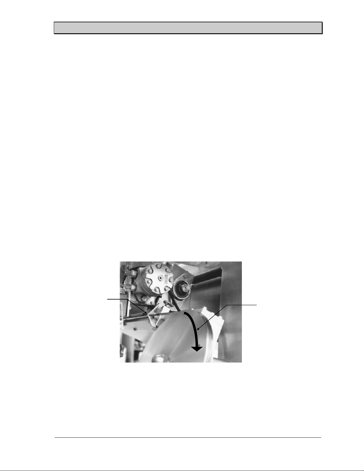
The blade scraper, sometimes called plow wiper, is made from two thin flat strips of Delrin that
rub against the top and bottom of the blade to remove residue as the blade is running. It is located
on the drive side top of the cutting blade. The blade scraper must be centered on the blade to insure
that all residue is removed from the blade. Loosen the two set screws holding the wipers in place
and move them as needed to center the scraper on the band blade.
Direction of Blade Travel
Figure 7. Blade scraper - Hydraulic Machines
The scraper must be adjusted so it makes firm contact with the blade as the blade enters the
point of the scraper. The top strip is hinge mounted so that it can be moved away from the
blade. To adjust the scraper move the lower scraper strip up until it touches and causes
approximately 1/8 inch deflection of the cutting blade. Then rotate the upper scraper strip
SS-10.DOC:1/26/2007 11:08 AM
Grote Company
11
Slicer/Applicator
down until it just contacts the blade. Firmly tighten both thumbscrews. Figure 7 shows a blade
scraper that is properly adjusted.
Check the blade scraper daily for noticeable wear. It should be replaced before wear becomes
excessive and wiping efficiency suffers. If uneven wear occurs, trim the edges of the scraper.
Blade Guide Maintenance
The blade guide should be checked for wear every 100 hours using the blade guide maintenance
tools furnished with each new machine. It should be checked for chips or cracks at every blade
change and replaced if any are present.
NOTE: It is important that the condition and wear of the blade guide be checked regularly.
Excessive wear of the blade guide reduces both the slice quality and the yield.
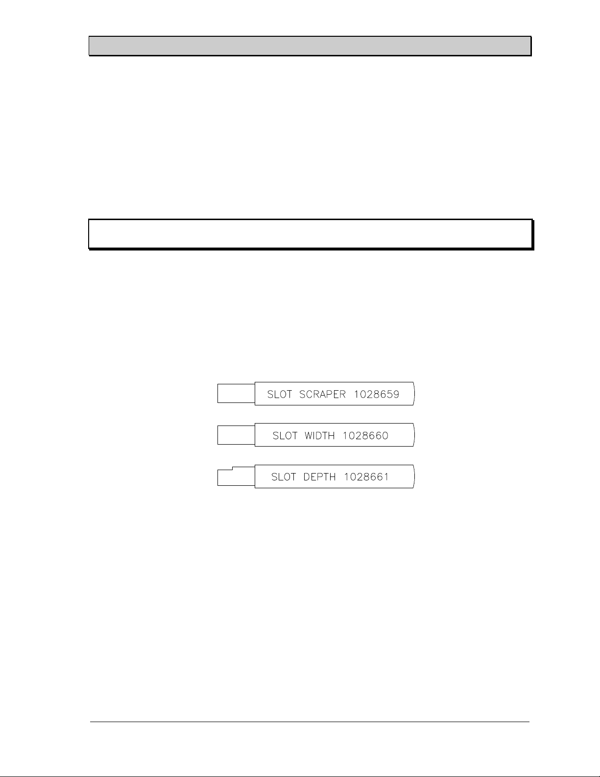
Blade Guide Maintenance Tools
A set of three Blade Guide Maintenance tools is included with each new slicer. One tool is a
scraper for cleaning the slot in the blade guide. The other two are for checking the blade guide
slot for excessive wear. It is important to check the blade guide if slice placement accuracy or
yield is affected. A worn slot may be the cause. The tools are shown below. Each tool has a
blue plastic handle.
Slot Scraper
The blade guide scraper (1028659) is for cleaning the blade guide slot during the
sanitation process. Simply insert the blade of the scraper into the slot and move it back
and forth along the entire length of the slot. It should move freely from one end of the
blade guide to the other. If an obstruction is met use care in dislodging it as the blade
guide is hardened steel and subject to cracking. You may wish to consult a Grote Service
Representative if the obstruction cannot be easily dislodged.
Slot Width Checking Tool
The "width" wear checking tool (1028660) is for checking the width of the blade guide
slot for excessive wear. Use the tool by attempting to insert the blade of the tool into the
slot of the blade guide. The blade of the tool is thicker than the standard slot width so that
SS-10.DOC:1/26/2007 11:08 AM
Figure 8. Blade Guide Maintenance Tools.
Grote Company
12
Slicer/Applicator
if the tool inserts easily into the slot the blade guide is worn excessively and may need to
be replaced. Check the blade guide along the entire length, especially in the region where
the food product has been passing across the guide.
CAUTION: The tool will not insert into a new blade guide. Do not force this tool into
the slot as damage to the guide may result.
Slot Depth Checking Tool
The "depth" wear checking tool (1028661) is for checking the depth of the blade guide slot
for excessive wear. Use the tool by inserting the blade of the tool into the slot until it
touches the bottom. If the notch in the tool inserts beyond the top edge of the blade guide
the blade guide slot is worn excessively and the blade guide may need to be replaced.
Check the blade guide along the entire length, especially in the region where the food
product has been passing across the guide.
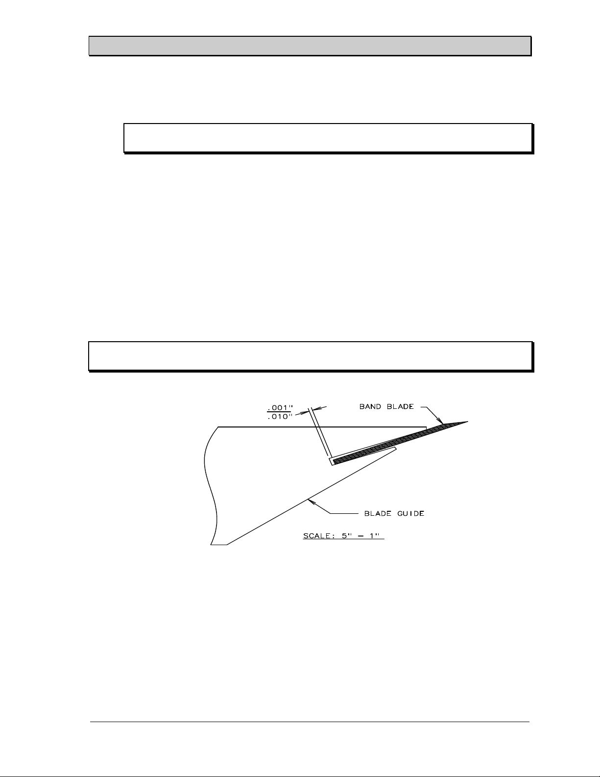
Blade Guide Adjustment
The blade guide must be adjusted so the band blade runs smoothly through the entire length of the
slot in order to get good slice quality.
NOTE: Check the adjustment where the blade both enters and leaves the blade guide slot. Verify
that the blade is not too loose and does not contact the edges of the slot.
Use the following steps to adjust the blade guide.
Figure 9. Blade Guide.
1. Loosen the four mounting bolts for the blade guide.
2. Check the blade tracking to make sure that it is correct.
3. Verify that the welded joint of the blade is not in the blade guide slot and hand tighten the
blade guide mounting bolts.
4. (See Figure 9) Adjust the blade guide forward or backward until the blade clearance on one
end is between 0.001" and 0.010" (approximately 1/2 of the band blade thickness). Snug the
bolts on that end.
SS-10.DOC:1/26/2007 11:08 AM
Grote Company
13
Slicer/Applicator
5. Repeat the procedure on the other end of the blade guide. Snug these bolts also.
6. Repeat the above two steps until both ends of the blade guide are properly adjusted. Tighten
the blade guide bolts.
7. Check the blade tracking. If the blade is not tracking properly, the adjustment of the blade
guide was done incorrectly. If this happens, the blade guide must be moved away from the
blade and tracking must be corrected before the blade guide adjustment procedure can be
repeated.
8. Reinstall the water applicator pad, rotate the plow wipers into position, and replace the
guards on the machine.
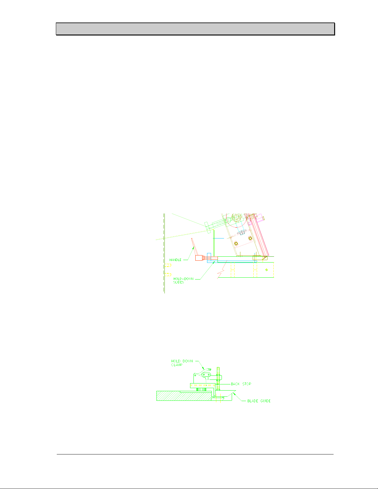
(Opt) Quick Disc Blade Guide Adjustment -
1. Loosen the two threaded handles located beneath the exit guard by turning them
counterclockwise (See Figure 10). Push the two handles forward towards the entry
side of the slicer to release the pins from the hold-down slides.
All-Electric Slicers
Figure 10. Quick Disconnect Blade Guide.
2. Loosen the two backstop bolts at each end of the blade guide. Release the two hold-
down clamps located at each end of the blade guide (See Figure 11).
Figure 11. Quick Disconnect Hold-Down Clamp.
SS-10.DOC:1/26/2007 11:08 AM
Grote Company
14

Slicer/Applicator
3. Verify that the blade is tracking correctly and the welded joint of the blade is not in the
blade guide slot.
4. (See Figure 9) Adjust the blade guide forward or backward until the blade clearance on
one end is between 0.001" and 0.010" (approximately 1/2 of the band blade thickness).
Move the backstop forward until it contacts the rear of the blade guide. Tighten the
backstop bolts and clamp down that end of the guide.
5. Repeat the procedure on the other end of the blade guide. Adjust the backstops and
clamp down this end of the guide also.
6. Repeat the above two steps until both ends of the blade guide are properly adjusted.
Once the guide is set, hand tighten the two threaded handles located beneath the exit
guard.
CAUTION: Do not overtighten. Turn the handles until a slight resistance is felt
between the slides and the center hold-down pins.
7. Check blade tracking. Repeat the adjustment if the blade is not tracking correctly.
8. Attach the water quick connects to the blade guide if applicable.
(Opt) Removing the Quick Disc Blade Guide -
All-Electric Slicers
1. Disconnect the water lines from the blade guide.
2. Loosen the two threaded handles located beneath the exit guard by turning them
counterclockwise. Release the pins from the hold-down slides by pushing the two handles
forward towards the entry side of the slicer.
3. Release the two hold down clamps located at each end of the blade guide. Remove the
clamps if necessary.
The blade guide, backtray and hold-down slides can now be removed.
(Opt) Reinstalling the Quick Disc Blade Guide -
1. Loosen the two threaded handles located beneath the exit guard (if necessary) by turning
them counterclockwise. Push the two handles forward towards the entry side of the slicer.
2. Install the blade guide by aligning the locating pins with the slots in the bearing bar.
3. Push the blade guide back until it contacts the stops at each end of the guide. Clamp each
end of the guide.
4. Once the guide is set, hand tighten the two threaded handles located beneath the exit guard.
CAUTION: Do not overtighten. Turn the handles until a slight resistance is felt between
the slides and the center hold-down pins.
5. In applicable, attach the water quick connects to the blade guide.
All-Electric Slicers
(Opt) Installing a New Quick Disc Blade Guide
1. Loosen the two threaded handles located beneath the exit guard (if necessary) by turning
them counterclockwise. Push the two handles forward towards the entry side of the Slicer.
SS-10.DOC:1/26/2007 11:08 AM
Grote Company
- All-Electric Slicers
15

Slicer/Applicator
2. Install the blade guide by aligning the locating pins with the slots in the bearing bar.
3. Loosen the two backstop bolts at each end of the blade guide.
4. Check the blade tracking to make sure that it is correct.
5. Verify that the welded joint of the blade is not in the blade guide slot.
6. Adjust the blade guide forward or backward until the blade clearance on one end is between
.03 mm and .3 mm (approximately 1/2 of the band blade thickness). Move the backstop
forward until it contacts the rear of the blade guide. Tighten the backstop bolts and clamp
down that end of the guide.
7. Repeat the procedure on the other end of the blade guide. Adjust the backstops and clamp
down this end of the guide also.
8. Repeat the above two steps until both ends of the blade guide are properly adjusted. Once
the guide is set, hand tighten the two threaded handles located beneath the exit guard.
CAUTION: Do not overtighten. Turn the handles until a slight resistance is felt between
the slides and the center hold-down pins.
9. If applicable, attach the water quick connects to the blade guide.
Blade Motor Belt Drive -
Hydraulic Slicers
On belt drive slicers, the belt that drives the blade pulley should be checked once a month for wear
and proper adjustment. Remove the belt cover and examine the belt. If it is glazed or cracked,
replace the belt. Check the tension in the belt and if it needs changing loosen the mounting bolts for
the blade motor and adjust the tension.
Product Holders
Height Adjustment
The product holder height is the clearance between the bottom edge of the product holder and
the tip of the band blade. This distance should be no less than 1/32" (0.8 mm) and no more than
1/16" (1.6 mm). If there is not sufficient clearance, slice quality will suffer. To check the
clearance, pull the product holder box pull pin and move the product holders across the blade.
SS-10.DOC:1/26/2007 11:08 AM
Grote Company
16

Slicer/Applicator
Product holder
clearance
Figure 12. Correct Product Holder Height.
Product Holder Height Adj -
Hydraulic Slicers
The following steps are used to adjust the product holder clearance. On split-head
machines each cluster must be adjusted separately.
Figure 14 shows the adjustment bolts for the product holder clearance and Figure 12
shows the proper height adjustment.
1. Install the product holders in the slicer and release the pull pin. Swing the holders
across the blade guide.
2. Loosen the hex head cap screws in the adjustment jack screw.
3. Raise or lower the product holder box by turning the adjustment jack screws until
the clearance between the bottom of the product holder and the tip of the band
blade is between 1/32" (0.8 mm) and 1/16" (1.6 mm).
4. When the product holder height is properly adjusted, tighten the hex head cap
screw.
5. Reinsert the pull pin and the adjustment is complete.
6. Repeat the above procedure for all product holder boxes.
SS-10.DOC:1/26/2007 11:08 AM
Grote Company
17

Slicer/Applicator
Product Holder Height Adj -
The height adjustment for All-Electric Slicers is similar to the Hydraulic Slicers. Each
slicing head must be adjusted using two jack bolts on each side at the top of the product
holders. The jack bolts rest on a support block welded to the frame (See Figure 13).).
1. Install the product holders in the slicer and release the pull pin. Swing the holders
across the blade guide.
2. Loosen the hex head cap screws in the adjustment jack screws.
3. Raise or lower the product holder box by turning the adjustment jack screws until
the clearance between the bottom of the product holder and the tip of the band
blade is between 1/32" (0.8 mm) and 1/16" (1.6 mm).
4. When the product holder height is properly adjusted, tighten the hex head cap
screws.
5. Reinsert the pull pin and the adjustment is complete.
6. Repeat the above procedure for all product holder boxes.
All-Electric Slicers
Alignment
The location of the product holder mounting brackets determines where the slices will be
applied on the conveyor. Product holders must be mounted directly over the area on the
conveyor where the slices are to be placed. The following steps should be used to adjust the
alignment of the product holders.
1. With the product holders still in the slicer, loosen the bolts on the product holder
mounting blocks.
2. Align the product holders so that the slices will fall in the proper place on the
conveyor. This adjustment is very important when applying slices to targets.
3. Tighten the bolts when the product holders have been properly aligned.
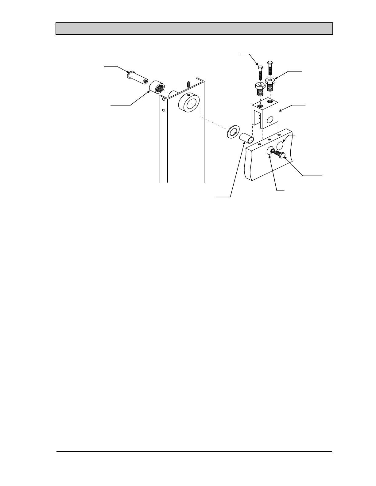
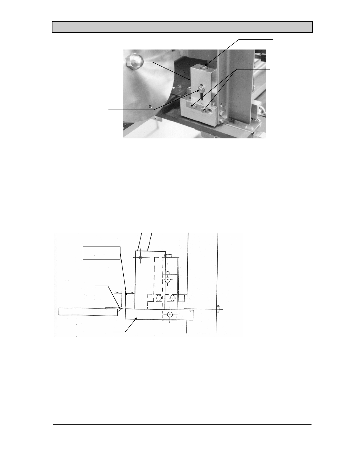
Pivot Point -
The product holder pivot point may need to be adjusted when product holders larger than 5" are
used. If the stroke length cannot be made long enough for the slicer to cut completely through
the product, change the pivot point to the extended position. Move the pivot point back to the
original position when the smaller product holders are placed back in the slicer. See Figure 14.
SS-10.DOC:1/26/2007 11:08 AM
Hydraulic Slicers
Grote Company
18
Slicer/Applicator
Hex head cap screw
Pivot shaft
Roller bearing
Inner race spacer
Figure 13. Product Holder Box Pivot Point - Hydraulic Machines
The following steps detail the procedure for changing to the extended position.
1. Remove the product holders.
Adjustment jack
screw
Adjustment
block
Regular position
Pivot bolt
Extended
position
2. Remove the bolt in the hole in front of the adjustment block. Loosen the hex head cap
screws and the adjustment jack screws.
3. Remove the pivot bolt and pull the insert (pivot shaft, roller bearing and inner-race
spacer) out of the pivot hole from the outside.
4. Move the pivot block to the extended position and reinstall the insert. Tighten the
pivot bolt into the insert.
5. Tighten the adjustment jack screw and the hex head cap screw. Place the remaining
bolt in the exposed hole on the top of the frame.
6. Adjust the height of the product holder box, the stroke length, and the stroke starting
point.
7. On multiple split-head machines, the lock pin assembly for heads 2, 4, and 6 must be
moved to the extended position whenever the product holder box is moved to the
extended position. Also adjust the roller arm of the limit switch mounted on the lock
pin assembly so that it is tripped near the end of the slicing stroke.
Slice Stroke Adjustment
Check the adjustments of the stroke length and stroke starting point by running at a very slow speed.
The motion of the product holder should be slow enough to allow the relative positions of the blade
and the product holder to be seen. Readjust as necessary until the stroke is centered over the blade
with the proper stroke length
SS-10.DOC:1/26/2007 11:08 AM
Grote Company
19
Slicer/Applicator
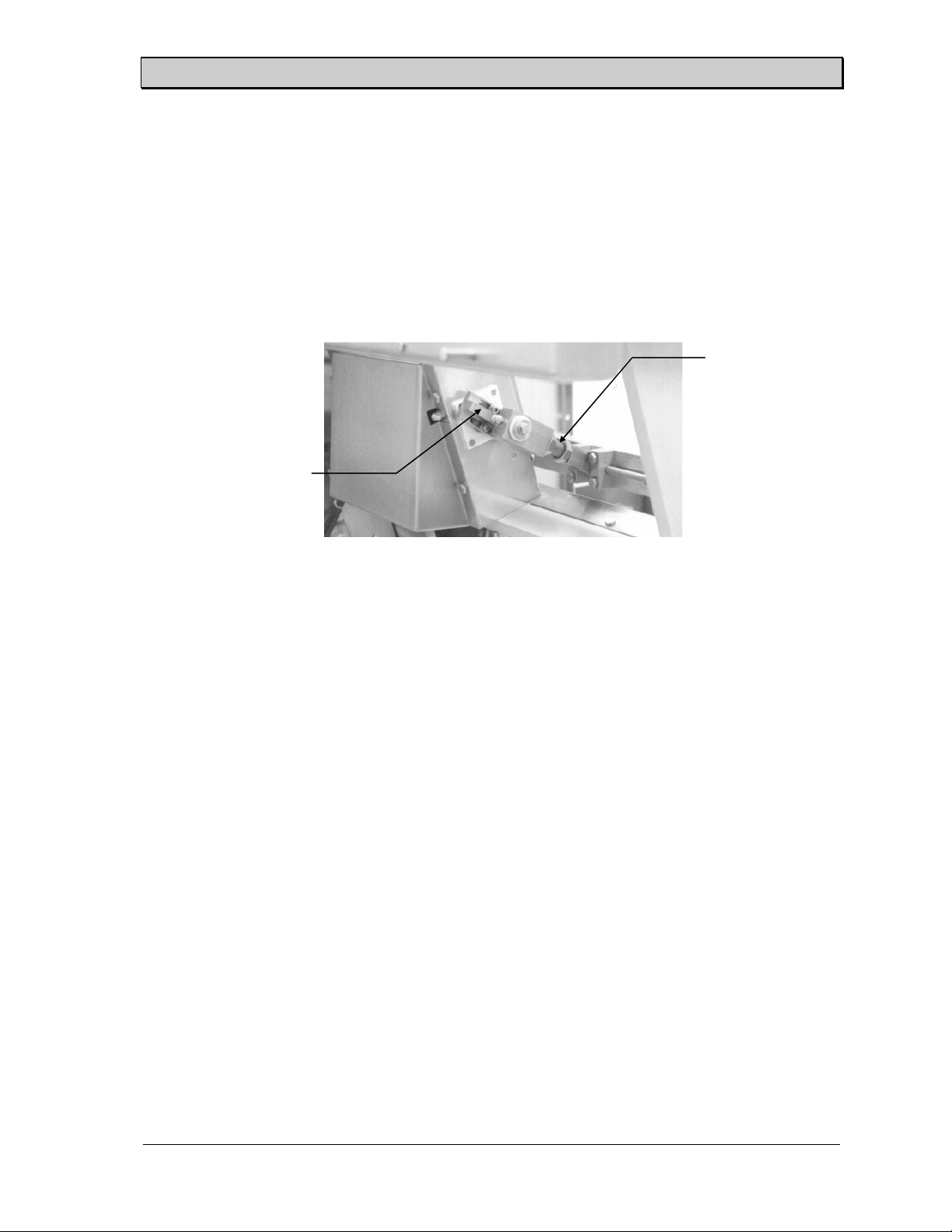
Stroke Length
Because the stroke length determines the distance that the product holder travels during the
slicing stroke, it needs to be adjusted whenever a different size product holder is installed in the
slicer. Keep distance as short as possible to minimize the time required to perform the slicing
and return motions. The product holder should have about 1/8" (3.2 mm) movement before the
front edge of the product holder crosses the blade. The back edge of the product holder should
go approximately 1/8" (3.2 mm) past the blade. Figure 15 shows the location of the stroke
length adjustment.
Stroke starting point
connecting rod
Stroke length adjustment
offset crank
Figure 14. Stroke Length Adjustment.
Adjust the stroke length by loosening the two socket head cap screws on the offset crank and
then moving the offset. Increasing the offset makes the stroke length longer and decreasing the
offset makes it shorter. Moving the adjustment by one tooth will change the stroke
approximately 1/2" (1/4" on either side of the product holder). Tighten the socket head cap
screws before starting the machine.
(Opt) Two-Position Stroke Adjustment -
All-Electric Slicers
Two pull pin positions on the side of the cluster box allow a quicker means of adjusting the
stroke length. Placing the pull pin in the upper locating hole, will increase the stroke length
approximately 25 mm.
Stroke Starting Point
Adjusting the stroke length provides the proper amount of product holder travel but the stroke
needs to be centered over the blade. The stroke starting point adjustment centers the slicing
stroke directly over the band blade by changing the length of the connecting rod between the
offset crank and the product holder box. This adjustment must always be checked after the
stroke length has been changed.
(See Figure 15) Adjust the stroke starting point by first loosening the jam nut of the connecting
rod and then releasing the pull pin. Turn the rod end in to move the starting and ending
positions toward the offset crank. Turn the rod end out to move the starting and ending
positions away from the offset crank. One complete turn of the rod end will move the starting
point approximately 1/8" (3.2 mm). Insert the pull pin when this adjustment is complete.
SS-10.DOC:1/26/2007 11:08 AM
Grote Company
20

Slicer/Applicator
Stroke Speed
Hydraulic Slicers - The speed of the slicing stroke is adjusted with the hydraulic flow-control valve
on the side of the slicer frame.
All-Electric Slicers - The speed of the slicing stroke is adjusted with the key pad on the operator
interface.
Stroke speed should be adjusted so that the cluster moves across the blade at a speed matching that
of the conveyor. Variations to this may be desired and can be determined upon actual application.
The speed of the overall stroke cycle must be fast enough to allow the cluster to be at the original
starting position when it is time to start the forward motion of the next cycle.
The maximum recommended stroke speed is dependent upon the stroke length. Longer stroke
lengths require more mechanical travel of the cluster assembly thus limiting the allowable number of
strokes per minute. The following table lists the maximum strokes per minute for the listed stroke
lengths.
Stroke Length
in Inches
2.0 1.5 5.3 176
2.5 2.0 5.0 168
3.0 2.5 4.8 160
3.5 3.0 4.6 152
4.0 3.5 4.3 144
4.5 4.0 4.1 136
5.0 4.5 3.8 128
5.5 5.0 3.6 120
6.0 5.5 3.4 112
Note: The maximum rating of the slicer is 176 strokes/minute.
Product Size
in Inches
Hydraulic Usage in
GPM
Maximum Recommended Strokes per Minute
Max Recommended
Strokes/Minute
Other factors that affect the stroke speed are:
1. Shuttle Conveyor - Slicers equipped with a shuttle conveyor should not exceed 120
strokes/minute.
2. Quick Return - The quick return feature becomes largely ineffective at speeds above 70
strokes/minute.
3. Product Pusher - Slicers equipped with a product pusher should not be run at speeds above
140 strokes/minute.
Changing the Thickness Range
Figure 16 shows the adjustment bolts for the slice thickness range and slice gap on standard
thickness trays.
SS-10.DOC:1/26/2007 11:08 AM
Grote Company
21
Slicer/Applicator
Slice thickness
adjustment bolt
Thickness tray mounting assembly
Hex head bolt
Figure 15. Slice Gap and Slice Thickness Adjustment Bolts - Hydraulic Machines
First, loosen the two hex head bolts in the side of the thickness tray mounting assemblies. The slice
thickness tray pivot point can then be lowered or raised by turning the adjusting bolts located in the
top of the adjustment blocks. When the tray is at the desired height, it is parallel to the top surface
of the blade guide. Verify that the thickness tray is level at this height and tighten the hex head
screws on the side of the adjustment blocks.
Slice Gap Adjustment -
Hydraulic Slicers
Slice gap adjustment
bolts
Slice gap
Blade guide
Thickness
Figure 16. Slice Gap.
Adjust the slice gap, see Figure 17, using the following table, so that there is enough room between
the thickness tray and the blade guide for the slices to pass through. Some variance from the values
in the table may be necessary to obtain closer accuracy on very thin slices or to prevent thicker
slices from "hanging up" on the blade guide.
SS-10.DOC:1/26/2007 11:08 AM
Grote Company
22
 Loading...