

Grosvenor Sateon Advance 2 Door Blade Installation Manual

Specifi cation
The Advance 2-Door Blade (Part No: SAT-ADV-BL-2D)
is a plug-in unit that can be purchased with either the
Advance Single-Blade Controller (Part No: SAT-ADV-CSNG-2D) or the Advance Multi-Blade Controller (Part
No: SAT-ADV-C-MLT-2D).
Each 2-Door Blade enables the connection of two
readers and two doors in Sateon access control
systems.
Clearly labelled connectors simplify the task.
Overview
Sateon Advance 2-Door Blade
Lock Switching Capacity
12V/24V, 4A max (Solid State output, current limited)
Card Reader interface
Wiegand, Clock/Data, RS485
Card Reader Supply, power limited
12V 500 mA, 5V 200 mA total (both ports)
Tamper, Door Sensor, Exit Switch, Aux, Inputs
5V pullup (2k2), max 12V in
Break Glass Input
24V max
Sounder, Valid, Invalid Output
500 max sink to GND (solid state), 12V max in
Aux Out
Isolated 30V, 300mA max, internally fused
External Lock Input Supply
24V max, 8A max. Must be externally fused
Operating Temperature
0 to +49°C (32 to 120°F)
Humidity
5-85±5% at 30±2°C (86±4°F)
Weight
140 g
Dimensions
197 x 60 x 28 mm
Sateon Advance 2-Door Blade
Installation Guide
Page 1
Electromagnetic Compatibility
This product complies with the following standards,
following the provisions of EMC Directive 2014/30/EU:
EN 55022:2010 Class B
EN50130-4:2011 inc A1:2014
IEC 62599-2:2010
WEEE
Please refer to www.grosvenortechnology.com/
legal-info/ for disposal instructions under EU
Directive 2012/19/EU.
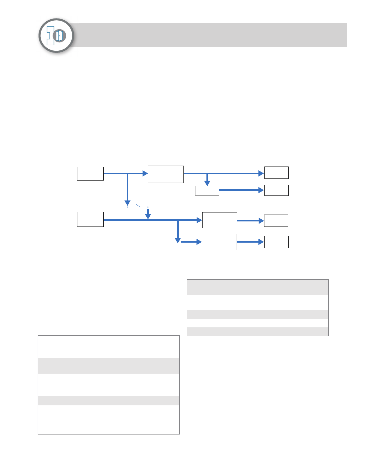
Current & Voltage
Measure
Overload Protection
Sounder 12V
Reader 12V
Reader 5V12V => 5V
Current & Voltage
Measure
Overload Protection
Current & Voltage
Measure
Overload Protection
12V Lock 1
(4 Amp max)
12V Lock 2
(4 Amp max)
Up to 8 Amp
12V IN
(from Controller)
12V/24V
External Lock
Supply
Input Power
The Advance 2-Door Blade draws 12V power from the
controller. The 2-Door Blade power draw is summed
as follows:
2-Door Blade Quiescent Current = 83 mA max @12V
(1.0W)
External Reader Current (200mA max @ 5V and/or
500mA max @ 12V)
External Door Lock Current (= 4A max per Lock @
12V)
Status LED
The main Blade LED Indicator is used to indicate
activity and state (see also the status LED on the
controller).
If the LED is continuously red, the 2-Door Blade is not
communicating with the controller.
Blade State is reported by fl ashing a code on the LED
every 15 seconds as follows:
5 blue fl ashes Board is not being monitored.
Probably no download to
controller from Sateon
5 red fl ashes Wrong device type confi gured, e.g.
a door is defi ned on an I/O Blade
3 red fl ashes Out of range device confi gured,
e.g. Input 3 defi ned when it only
supports 2
5 green fl ashes No devices confi gured for board
5 yellow fl ashes Reports electrical issues, such
as current tripped, over voltage,
under voltage, over current, under
current
Blade LED indicators
Blade Activity is reported as follows:
Yellow fl icker (lasts
about 30 seconds)
Firmware download in
progress
Green blink (every 5
seconds)
Board running OK
Blue blink Read
Yellow blink Input state change
Red blink Output state change
Other LED Indicators
There are three diagnostic red LEDs on a 2-Door
Blade. Note that these LEDs cannot be seen when the
controller and Blade are in the enclosure.
LED2 – Lock 1 Power. This will be on if Door 1 on the
Blade has not been defi ned or if the Lock 1 power
current limit has been tripped
LED3 – Lock 2 Power. This will be on if Door 2 on the
Blade has not been defi ned or if the Lock 2 power
current limit has been tripped
LED4 – Reader Power (includes other connections,
such as sounders). This will be on if the Blade has
not been defi ned or the current limit has been
tripped
External Lock Supply
For systems with 24V door locks, or locks requiring
more power than the controller can provide, the
2-Door Blade supports an external lock power supply.
This operates automatically if available, where the
Blade will fi nd the external lock power supply for the
locks, otherwise, it uses internal power. This cannot be
changed without powering off .
External lock power is separate from the controller
power. It will need an independent back-up if required:
it is not supported by the controller battery.
Power Options
Page 2
 Loading...