

Groppo Ferroli Domina Plus F 24-30 E Technical Manual

Supplied by HeatingSpares247.com
Wall-Mounting Gas
Boiler with antifreeze
for tap water
Airtight Chamber, for
Hot Water and Heating
TECHNICAL
DOMINA PLUS F 24-30 E
FERELLA EXTRA F 24-30 MEL
MANUAL
EDITION
092002

DOMINA PLUS F 24 - 30 E
Supplied by HeatingSpares247.com
FERELLA EXTRA F 24 - 30 MEL
1. Technical characteristics and data ........................................................ 3
1.1 Introduction .............................................................................................................. 3
1.2 Dimensions and connections .................................................................................. 4
1.3 General view and main components ....................................................................... 8
1.4 Technical data table ............................................................................................... 10
2. Hydraulic circuit - heating ................................................................... 11
2.1 Hydraulic circuit - heating ...................................................................................... 11
2.2 Hydraulic circuit - tap water ................................................................................... 15
2.3 Gas circuit .............................................................................................................17
2.4 Burner unit ............................................................................................................. 21
2.5 Fume circuit .......................................................................................................... 23
2.6 Electrical circuit ..................................................................................................... 27
3. Operation ............................................................................................ 30
3.1 Operating principle ................................................................................................ 30
3.2 Operating diagram................................................................................................. 32
3.3 Control panel ......................................................................................................... 33
3.4 Adjustments ........................................................................................................... 35
3.5 Operating parameter adjustment .......................................................................... 38
4. Unit self-diagnosis .............................................................................. 43
2
Version - 09.2002
DOMINA PLUS F 24 - 30 E
Supplied by HeatingSpares247.com
FERELLA EXTRA F 24 - 30 MEL
1. TECHNICAL CHARACTERISTICS AND DATA
1.1 Introduction
Our unit is a high-efficiency heat generator for heating and hot water production running on natural or liquefied
petroleum gas (configurable at the time of installation) and regulated by an advanced microprocessor control
system.
The boiler shell consists of a copper laminar exchanger whose particular shape guarantees high exchange
efficiency under all operating conditions and an open-flue burner equipped with electronic ignition and ionization
flame control.
The boiler is totally sealed off from the installation room: the air needed for combustion is drawn from outside
and the flue gases are expelled by a fan. The boiler outfit moreover includes a variable speed circulator,
expansion tank, flow meter, safety valve, filler cock, air pressure switch, water pressure switch, temperature
sensors, safety thermostat and an antifreeze thermostat with the relevant heating elements.
Thanks to the microprocessor control and adjustment system with advanced self-diagnosis, unit operation is
for the most part automatic. The power for heating is automatically governed by the control system according
to the indoor and outdoor characteristics (with an optional outdoor sensor installed), the characteristics of the
building and of its location. The power for hot water is automatically and continually governed to ensure a fast
delivery and comfort under all operating conditions.
The display continuously provides information on the unit's operating status and it is easily possible to obtain
additional information on the sensor temperatures, set-points, etc. or configure them. Any operating trouble
associated with the boiler or system is immediately signalled by the display and, if possible, corrected
automatically.
General Warnings
· Installation and maintenance must be carried out by professionally qualified personnel, according
to current regulations and the manufacturer's instructions.
· Incorrect installation or poor maintenance can cause damage or physical injury. The manufacturer
declines any responsibility for damage caused by errors in installation and use or by failure to
follow the manufacturer's instructions given in the instructions manual.
· Before carrying out any cleaning or maintenance operation, disconnect the unit from the electrical
power supply using the switch and/or the special cut-off devices.
Certification
The CE marking demonstrates that Ferroli gas units conform to the requirements contained in the
applicable European directives.
In particular, this unit complies with the following EU directives:
· Gas Appliance Directive 90/396 assimilated with Italian Presidential Decree DPR 15.11.96 no. 661
· Efficiency Directive 92/42 assimilated with Italian Presidential Decree DPR 15.11.96 no. 660
· Low Voltage Directive 73/23 (amended by 93/68)
· Electromagnetic Compatibility Directive 89/336 (amended by 93/68) assimilated with Italian
Presidential Decree DPR 15.11.96 no. 615
Version - 09.2002
3
DOMINA PLUS F 24 - 30 E
Supplied by HeatingSpares247.com
FERELLA EXTRA F 24 - 30 MEL
1.2 Dimensions and connections
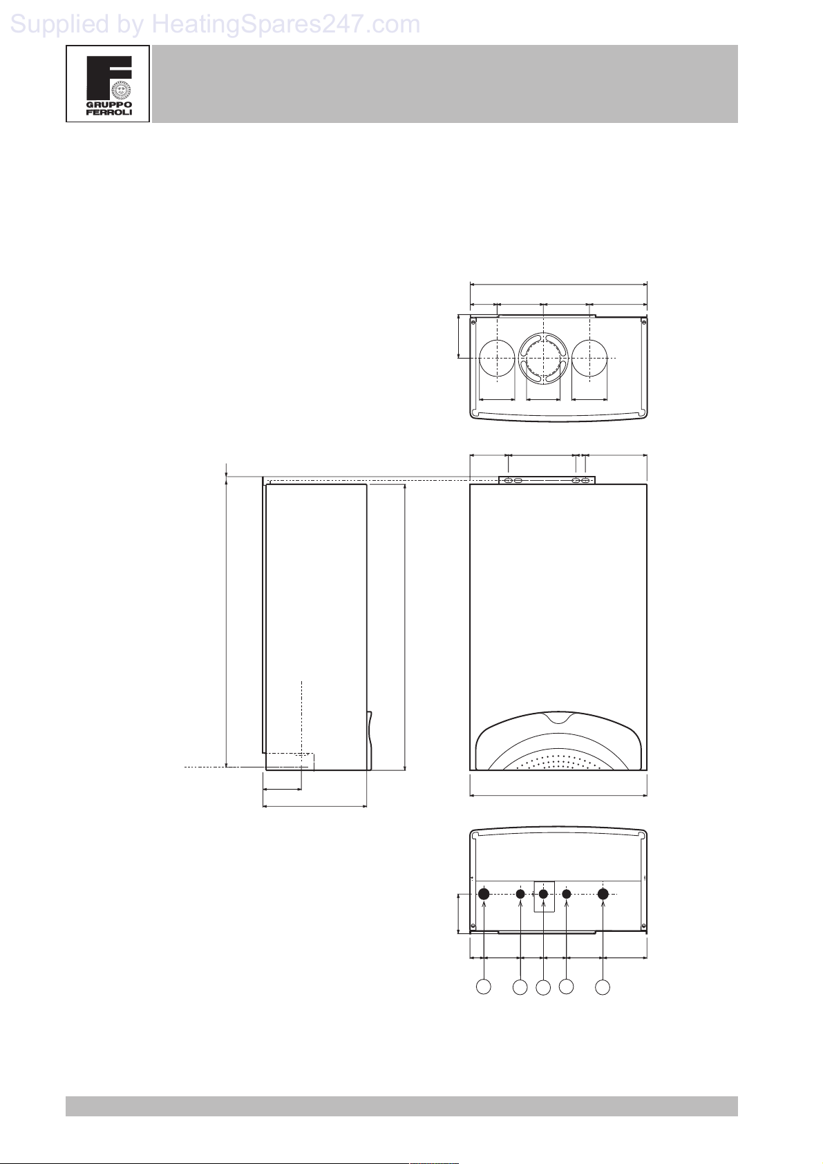
Domina Plus F 24 E version
Top view
460
15012012070
110
10
725
Connections axis
Connections axis
100
270
720
80 80
80
175100
460
16025
Key
1 System delivery
2 Tap water outlet
3 Gas inlet
4 Tap water inlet
5 System return
4
100
1
2
Bottom view
1149560609536
4
3
5
Version - 09.2002
DOMINA PLUS F 24 - 30 E
Supplied by HeatingSpares247.com
FERELLA EXTRA F 24 - 30 MEL
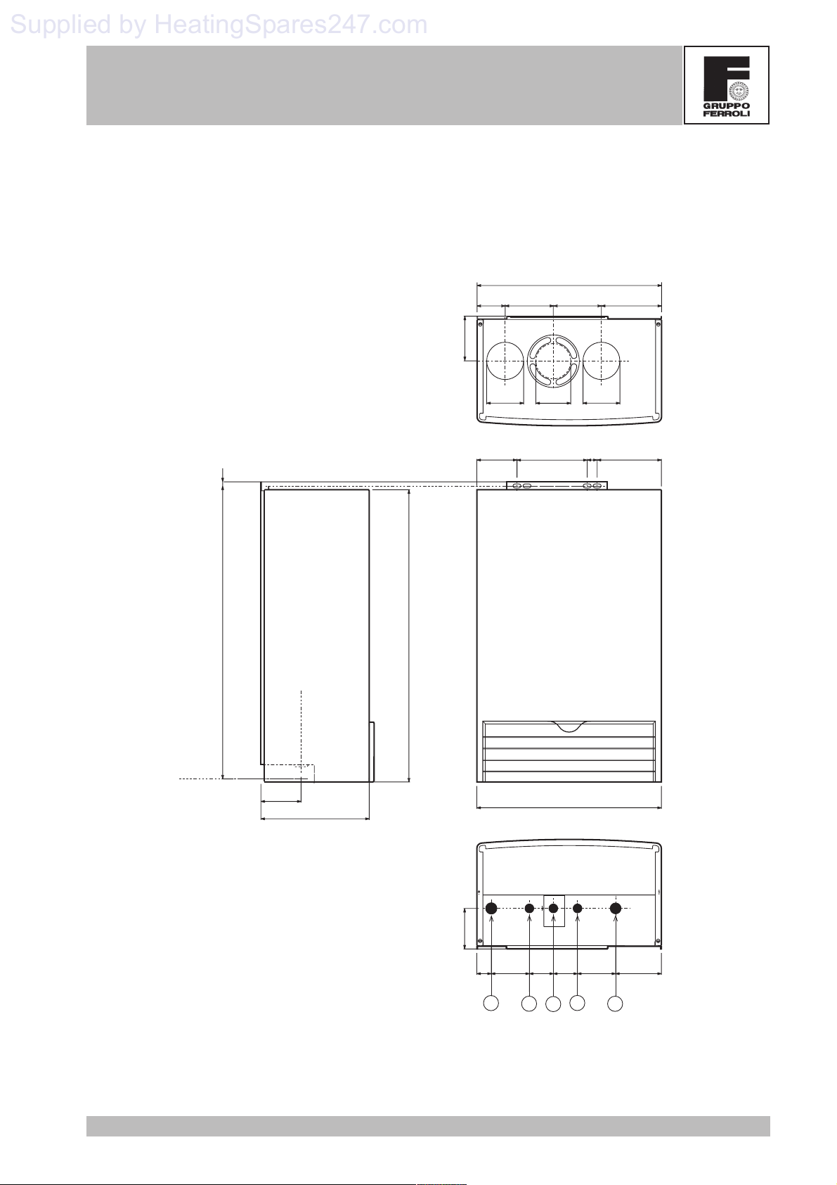
Ferella Extra F 24 MEL version
110
Top view
460
15012012070
10
725
Connections axis
Connections axis
100
270
720
80 80
80
175100
460
16025
Key
1 System delivery
2 Tap water outlet
3 Gas inlet
4 Tap water inlet
5 System return
Version - 09.2002
100
1
2
Bottom view
1149560609536
4
3
5
5
DOMINA PLUS F 24 - 30 E
Supplied by HeatingSpares247.com
FERELLA EXTRA F 24 - 30 MEL
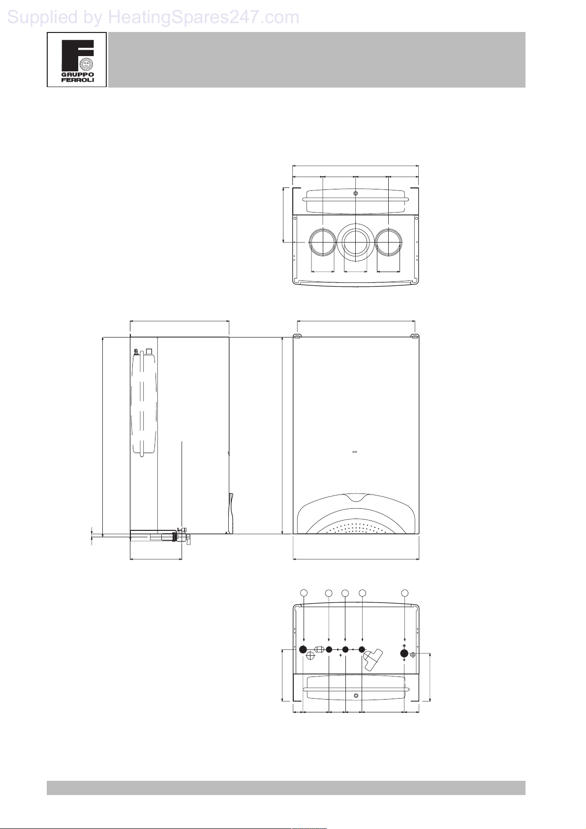
Domina Plus F 30 E version
200
Top view
460
120120110
110
14
733
Connections axis
420
80
8080
430362
189
Key
1 System delivery
2 Tap water outlet
3 Gas inlet
4 Tap water inlet
5 System return
189
6
460
1
23
36 95 60 60 155 54
4
5
Bottom view
175
Version - 09.2002

DOMINA PLUS F 24 - 30 E
Supplied by HeatingSpares247.com
FERELLA EXTRA F 24 - 30 MEL
Ferella Extra F 30 MEL version
200
Top view
460
120120110
110
14
733
362
Connections axis
720
80
8080
430
189
Key
1 System delivery
2 Tap water outlet
3 Gas inlet
4 Tap water inlet
5 System return
Version - 09.2002
460
1
23
189
36 95 60 60 155 54
4
Bottom view
5
175
7
DOMINA PLUS F 24 - 30 E
Supplied by HeatingSpares247.com
FERELLA EXTRA F 24 - 30 MEL
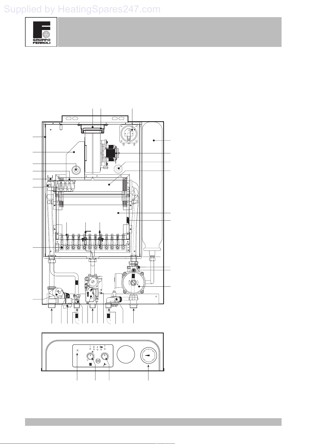
1.3 General view and main components
F 24 E/MEL version
29 43
187
5
28
90
132
49
34
81
8222
20
21
R4
3
4
2
1
5
0
6
114
OUT
R3
IN
MIN
R2
10 874 784 85 44
14 42 9 11
RESET
°C °C
R1
136
56
16
91
27
19
26
36
73
32
Key
5 Airtight chamber
7 Gas inlet
8 Tap water outlet
9 Tap water inlet
10 System delivery
11 System return
14 Safety valve
16 Fan
19 Combustion chamber
20 Burner assembly
21 Main nozzle
22 Burner
26 Combustion chamber insulation
27 Copper exchanger for heating and
tap water
28 Fume manifold
29 Fume outlet manifold
32 Heating circulator
34 Heating temp. sensor
36 Automatic air vent
42 Tap water temperature sensor
43 Air pressure switch
44 Gas valve
49 Safety thermostat
56 Expansion tank
63 Heating temperature setting
73 Antifreeze thermostat
74 System filler cock
81 Ignition electrode
82 Detection electrode
84 1st gas valve operator
85 2nd gas valve operator
90 Fume detection point
91 Air detection point
98 Off-On-Reset switch
114 Water pressure switch
132 Fume deflector
136 Flow meter
145 Water gauge
157 Tap water temperature setting
187 Fume diaphragm
R1-R2-R3-R4 Antifreeze heating elements
98 63 157
145
8
Version - 09.2002
DOMINA PLUS F 24 - 30 E
Supplied by HeatingSpares247.com
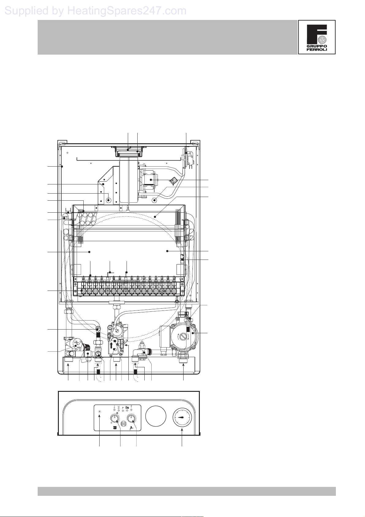
FERELLA EXTRA F 24 - 30 MEL
F 30 E/MEL version
28
90
132
49
34
56
20
21
73
114
29 43187
Key
5 Airtight chamber
7 Gas inlet
8 Tap water outlet
5
16
91
27
9 Tap water inlet
10 System delivery
11 System return
14 Safety valve
16 Fan
19 Combustion chamber
20 Burner assembly
21 Main nozzle
22 Burner
26 Combustion chamber insulation
27 Copper exchanger for heating and
tap water
28 Fume manifold
19
818222
26
29 Fume outlet manifold
32 Heating circulator
34 Heating temp. sensor
36 Automatic air vent
42 Tap water temperature sensor
43 Air pressure switch
44 Gas valve
49 Safety thermostat
56 Expansion tank
36
63 Heating temperature setting
73 Antifreeze thermostat
74 System filler cock
81 Ignition electrode
R3
OUT
IN
MIN
R4
GRUNDFOS
32
82 Detection electrode
84 1st gas valve operator
85 2nd gas valve operator
90 Fume detection point
91 Air detection point
98 Off-On-Reset switch
R2
R1
114 Water pressure switch
132 Fume deflector
10 8 784 85 44
74
14 42 9 11
136
136 Flow meter
145 Water gauge
157 Tap water temperature setting
187 Fume diaphragm
RESET
°C °C
3
4
2
1
5
0
6
R1-R2-R3-R4 Antifreeze heating elements
98 63 157
Version - 09.2002
145
9
FERELLA EXTRA F 24 - 30 MEL
Supplied by HeatingSpares247.com
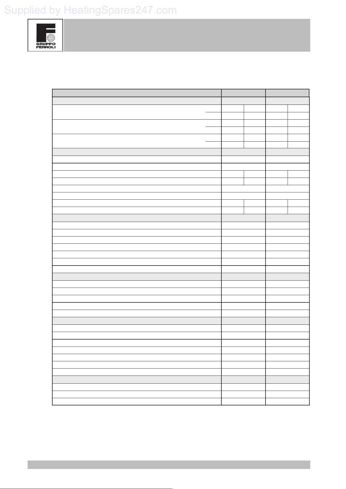
1.4 Technical data table
DOMINA PLUS F 24 - 30 E
DOMINA PLUS - FERELLA EXTRA
Powers Pmax Pmin
Heating Power (Net Heat Value - Hi)
Useful Heating Power 80°C - 60°C
Tap Water Heating Power
Gas supply Pmax Pmin
Natural Gas main nozzles (G20) mm 12 x 1.30
Natural Gas supply pressure (G20) mbar 20.0
Pressure at Natural Gas burner (G20) mbar 11.8 2.5
Natural Gas delivery (G20) nm
LPG main nozzles (G31) mm 12 x 0.77
LPG supply pressure (G31) mbar 37.0
Pressure at LPG burner (G31) mbar 36.0 7.8
LPG delivery (G31) kg/h 2.00 0.89
Heating
Maximum working temperature in heating °C 90
Maximum working pressure in heating bar 3
Safety valve bar 3
Minimum working pressure in heating bar 0.8
Expansion tank capacity litres 7
Expansion tank pre-filling pressure bar 1
Boiler water content litres 0.8
Tap water
Maximum hot water production Dt 25°C l/min 13.6
Maximum hot water production Dt 30°C l/min 11.3
Maximum working pressure in hot water production bar 9
Minimum working pressure in hot water production bar 0.25
Hot water content litres 0.8
Dimensions, weights connections
Height mm 760
Width mm 460
Depth mm 272
Weight kg 38
Gas system connection inches 1/2
Heating system connections inches 3/4
Hot water circuit connections inches 1/2
Electrical power supply
Max electrical power absorbed W 125
Power voltage/frequency V/Hz 230/50
Electrical protection rating IP 44
kW 25.8 11.5
kcal/h 22,200 9,900
kW 23.8 9.7
kcal/h 20,400 8,300
kW 23.8 9.7
kcal/h 20,400 8,300
3
/h 2.73 1.22
24kW 30kW
Pmax Pmin
33.1 14.5
28,500 12,500
30.0 12.7
25,800 10,900
30.0 12.7
25,800 10,900
Pmax Pmin
16 x 1.25
20.0
13.0 2.5
3.50 1.53
16 x 0.75
37.0
35.5 7.0
2.60 1.14
90
3
3
0.8
10
1
1.5
17.2
14.3
9
0.25
0.8
760
460
363
48
1/2
3/4
1/2
125
230/50
44
10
Version - 09.2002
DOMINA PLUS F 24 - 30 E
Supplied by HeatingSpares247.com
FERELLA EXTRA F 24 - 30 MEL
2. PRODUCT FRAMEWORK AND INTERNAL
COMPONENTS
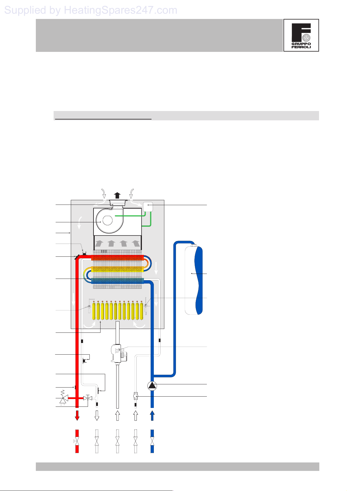
2.1 Hydraulic circuit - heating
Hydraulic diagram for heating
When there is a call for heat, the room thermostat or control system make the burners ignite and the circulation
pump come into operation. The heat contained in the products of combustion is transferred to the water by the
system via the exchanger. For more details on the operating logic, refer to chap.3.
Key
29-187
16
49
34
27
82
20
73
5 Airtight chamber
-
+
5
R1
R2
43
7 Gas inlet
8 Tap water outlet
9 Tap water inlet
10 System delivery
11 System return
14 Safety valve
16 Fan
20 Burner assembly
27 Heat exchanger
29 Fume outlet collar
32 Heating circulator
56
34 Heating temperature sensor
42 Tap water temperature sensor
43 Air pressure switch
44 Gas valve
81
49 Safety thermostat
56 Expansion tank
73 Antifreeze thermostat
74 System filler cock
81 Ignition electrode
82 Detection electrode
114 Water pressure switch
136 Flow meter
44
187 Fume diaphragm
R1-R2-R3-R4 Antifreeze heating elements
42
114
14
74
Version - 09.2002
R3
8
7
R4
1110
9
32
136
11
DOMINA PLUS F 24 - 30 E
Supplied by HeatingSpares247.com
FERELLA EXTRA F 24 - 30 MEL
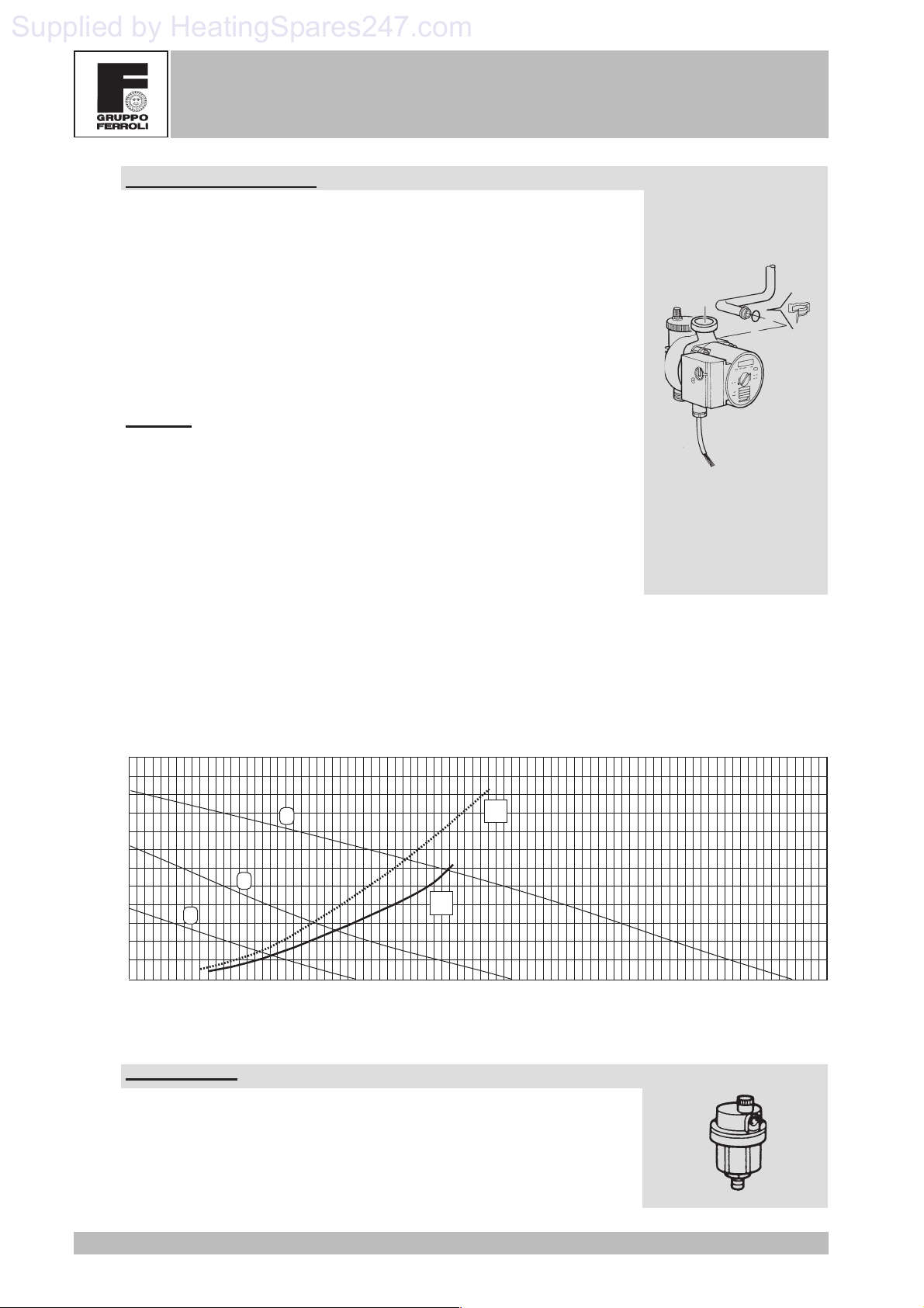
Circulator (230v/50Hz)
Located on the heating circuit return, it is connected directly to the exchanger
via special forks and connected to the system via a threaded brass section. It has
three delivery/head levels (see diagram). Changing the delivery/head changes
the speed of the water flowing through the boiler exchanger and as a result the
temperature difference (DT) between heating delivery and return. Clearly,
increasing the delivery of the circulator decreases DT and vice versa. If it is not
used for a long time, the impeller might "jam" due to debris in the water. With the
front screw it is possible to access the impeller, which can be freed with the aid
of a screwdriver. The connection to the expansion tank and the air separator is
installed on the pump casing.
Checks
If the pump doesn't work:
· Check that the impeller is free to turn by turning the screw on the front with a
screwdriver.
· Check that both the card and the pump connection are powered.
· If there is no power supply, check the card.
· If there is power, change the pump.
Key
1 - 2 - 3 = Pump selector position
mC.A.
6
5.5
5
4.5
4
3.5
3
2.5
2
1.5
1
0.5
0
0 0.25 0.75 1.25 1.75 2.25 2.752.51.50.5 1 2 3
1
3
2
A
B
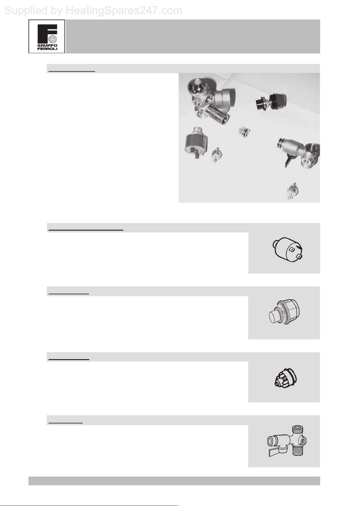
Air separator
This is used to expel the air in the heating circuit automatically. On boilers with
a twin heat exchanger, it is located on the pump casing. It is normally accessible
either via the fork or by simply unscrewing it from its seat.
A = Losses of head 24kW version
B = Losses of head 30kW version
3.2 3.4 3.6 3.8 4
3
m
/ h
12
Version - 09.2002

DOMINA PLUS F 24 - 30 E
Supplied by HeatingSpares247.com
FERELLA EXTRA F 24 - 30 MEL
Expansion tank
It is connected to the pump casing via a pipe with a fork connection. On the 24kW version, it is located above
the pump, while on the 30kW version it is located behind the exchanger, inside the frame. The expansion tank
contains a diaphragm in contact, on one side, with the system water and, on the other side, with the air under
pressure (pre-loaded to 1 bar) inside the tank. By the expansion of the diaphragm and ensuing compression
of the air, the tank compensates for the thermal expansion of the water in the heating system.
Version 24kW
7 litre
Version 30kW
10 litre
Twin Heat Exchanger
The exchanger is a copper laminar assembly. It comprises a thickly finned portion, three circular pipes
containing the heating water and, inside them, another three pipes in the form of a spiral containing the tap water.
The heating water exchanges directly with the burnt gases, while the tap water does not have this kind of
exchange, it receives heat indirectly from the water in the three heating pipes. In this way, the surface of the
coil does not reach very high temperatures so less scale gets formed. In addition, being very small, it makes
the water speed very high over its entire section, making mineral deposits of any kind negligible. The typical
"omega" shape of the finning ensures an even distribution of the heat over all the finning, with consequent
benefits in terms of exchange efficiency and the life of the exchanger. A special surface treatment protects the
exchanger against oxidation and corrosion.
Version - 09.2002
13
DOMINA PLUS F 24 - 30 E
Supplied by HeatingSpares247.com
FERELLA EXTRA F 24 - 30 MEL
Hydraulic unit
This is a single piece of brass to which the exchanger
delivery is connected for ease of access. It
accommodates a number of safety and adjustment
components.
The hydraulic unit includes:
- safety valve
- water pressure switch
- heating sensor
- filler cock
- tap water sensor
- tap water check valve
Water pressure switch
It ensures a minimum pressure for the system. It is normally open (NO) and
closes the contact when the pressure exceeds 0.5 bar. It works on low voltage.
Safety valve
It opens if the pressure exceeds 3 bars, making boiler operation safer and
protecting it against overpressure. You are strongly recommended not to use this
valve to drain the system; once open, dirt could remain inside it, preventing it from
closing completely.
Check valve
This is necessary to ensure no water returns from the heating system to the tap
water circuit.
Filler cock
This is located between the heating delivery and the tap water outlet. It is not fitted
on the boiler for some markets such as the British and Belgian ones.
14
Version - 09.2002
 Loading...